manuals.online logo
Brands
  1. Home
  2. •
  3. Brands
  4. •
  5. CALEFFI
  6. •
  7. Control Unit
  8. •
  9. CALEFFI 2527 Series User manual

CALEFFI 2527 Series User manual

01165/09 GB
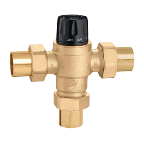
Adjustable anti-scald thermostatic
mixing valve for solar thermal systems
2527 series
Function
The thermostatic mixing valve is used in solar thermal systems for
the production of domestic hot water.
It is designed to maintain the set temperature of the mixed water
supplied to the user when there are variations in the temperature
and pressure conditions of the incoming hot and cold water or in
the flow rate.
It is also fitted with an anti-scald safety function, which immediately
shuts off the hot water flow in case of a failure in the cold water
supply at the inlet.
This particular series of mixing valves can function continuously at
the high temperatures of the incoming hot water from the solar
storage tank.
Product range
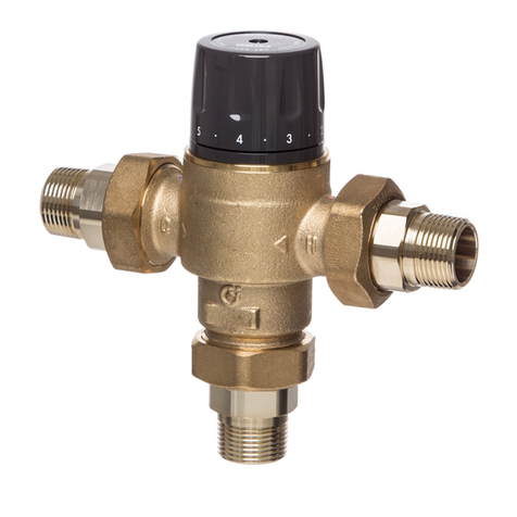
2527 series Adjustable anti-scald thermostatic mixing valve for solar thermal systems.
Complete with strainers and check valves at the inlets sizes 1/2” and 3/4”
Technical specifications
Materials
Body: dezincification resistant alloy
EN 12165 CW602N, chrome plated
Obturator: PSU
Springs: stainless steel
Seal components: EPDM
Control knob: ABS
Performance
Adjustment range: 35–55°C
Accuracy: ±2°C
Max. working pressure (static): 10 bar
Max. working pressure (dynamic): 5 bar
Max. inlet temperature: 100°C
Max. inlet pressure ratio (H/C or C/H): 2:1
Minimum temperature difference between the inlet hot water
and the outlet mixed water to ensure anti-scald performance: 10°C
Min. flow rate for stable operation: 4 l/min
Performance to standards: NF 079 doc. 8, EN 15092
EN 1111, EN 1287
Connections: 1/2” and 3/4” M with union
Dimensions
CALEFFI
R
E
G
I
S
T
E
R
E
D
BS EN ISO 9001:2000
Cert. n°FM 21654
UNI EN ISO 9001:2000
Cert. n°0003
A
1/2”
3/4”
E
81,5
82
D
126,5
127
F
45
45
C
125
134
B
62,5
67
Code
252714
252713
Weight (kg)
0,58
0,81
F
E
D
BB
C
A
A
A
High temperature solar systems
In solar thermal systems with natural circulation in the primary circuit and a water storage with heating jacket, the temperature of the domestic
water in the storage can vary considerably depending on the degree of solar radiation and can reach very high temperatures over long periods.
In summer, and if there is little water usage, the hot water at the
storage outlet can actually reach temperatures around 98°C before
the temperature and pressure safety relief valves are actuated.
At these temperatures, the hot water cannot be used directly,
because of the danger of scalding for users.
Water temperatures over 50°C can cause burns very quickly.
For example, at 55°C, partial burn occurs in about 30 seconds,
whereas at 60°C partial burn occurs in about 5 seconds.
It is therefore necessary to use a thermostatic mixing valve able to:
• reduce the temperature of the water distributed throughout the
domestic water system to a value lower than that in the storage
and suitable for the end user. For reasons of safety, it is
recommended to set the temperature of the mixed water
distributed to the users to values no higher than 50°C;
• keep mixed water temperature constant despite variations in inlet
temperature and pressure.
• continue functioning over time without any loss in performance
and without problems due to the continuously high temperature
of the incoming water;
• enable the high temperature water in the tank to last longer, by
distributing it to the user circuit at a reduced temperature.
• have an anti-scald safety function in case of failure of the cold
water supply.
Operating principle
The thermostatic mixing valve mixes the hot and cold water at the
inlet so as to maintain the mixed water at a constant set temperature
at the outlet. A thermostatic element is fully immersed in the mixed
water outlet passage. It contracts or expands, moving an obturator
which controls the passage of hot or cold water at the inlet. If there
are changes in the inlet temperature or pressure, the internal
element automatically reacts to restore the set temperature at the
outlet.
Construction details
High resistance to temperature
Internal control components are
designed to maintain constant the mixing
valve performance with inlet hot water
temperatures up to 100°C, in continuous
operation.
Anti-scale materials
The materials used in constructing the
mixing valve were selected to eliminate
seizing due to limescale deposits.
All functional parts have been made
using a special anti-scale material with
low friction coefficient, which ensures
over time performance.
Anti-scald safety function
As a safety measure, in case of failure of
the cold water supply, the valve
immediately shuts off the flow of the hot
water. This prevents dangerous burns.
This performance is guaranteed if there
is a minimum temperature difference
between the inlet hot water and the
outlet mixed water of 10°C. Also in case
of failure of the hot water supply, the
valve shuts off the cold water port and
thus the outlet mixed water to prevent
dangerous thermal shocks.
COLD
HOT
MIXED
Code 252714
Code 252713
Exposure time to cause partial burns
Temperature Adults Children 0-5 years
70°C 1 s --
65°C 2 s 0,5 s
60°C 5 s 1 s
55°C 30 s 10 s
50°C 5 min 2,5 min
Commissioning
In view of the special applications for which the
thermostatic mixing valve is used, it must be
commissioned according to current regulations, by
qualified technicians equipped with suitable
temperature measurement instruments.
We recommend using a digital thermometer for
measuring the mixed water temperature.
Temperature adjustment
The temperature of the mixed water sent to the user
is set at the desired value using the control knob
with the graduated scale on the valve.
Hydraulic characteristics
Δ
p (bar)
1,5
Δp (m
w
.
g
.)
10
20
50
0,5
1
2
5
Flow rate
(l/min) (m3/h)
5
0,2
1,0
0,5
0,3
0,2
0,1
0,05
15
10
5
3
2
1
0,5
252713252714
Code
2527
14
2527
13
Ø
1/2”
3/4”
Kv (m3/h)
1,5
1,7
Use
In view of their flow characteristics, the 2527 series thermostatic mixing valves can
be installed to control the temperature for individual user fittings (for example wash
basin, bidet, shower) or multiple user fittings.
To ensure stable operation, the mixing valve must be guaranteed a minimum flow
rate of 4 l/min. The system must always be sized in accordance with current
legislation regarding the nominal flow rate to each user fitting.
Selecting the mixing valve size
If the design flow rate is known, taking into account simultaneous use of the sanitary
appliances, the size of the mixing valve is chosen by checking on the graph
provided the head loss produced. In this case, it is necessary to check the
available pressure, the head loss in the system downstream of the mixing valve and
the residual pressure to be guaranteed to the user appliances.
Installation
Before installing the mixing valve, the pipework must be flushed to ensure that no
circulating impurities can compromise its operation. It is recommended to install
always strainers of adequate performance at the water inlet from the hydraulic
network. The 2527 series mixing valve is equipped with strainers at the cold and
hot water inlets. The 2527 series thermostatic mixing valve must be fitted according
to the installation diagram provided in the instruction manual or in this brochure.
The 2527 series thermostatic mixing valve can be installed in any position, vertically
or horizontally.
The following marks are indicated on the valve body:
· hot water inlet by the letter “H” (Hot)
· cold water inlet by the letter “C” (Cold)
· mixed water outlet by the word “MIX
Check valves
In systems with thermostatic mixing valves, check valves should be installed to
prevent undesired backflow. The 2527 series thermostatic mixing valve
incorporates check valves on the hot and cold water inlets, specific for solar hot
water high temperatures.
Thermal transient
During transient, following rapid changes in pressure,
temperature or flow rate, the outlet mixed water
temperature increases with respect to the initial set
point and this increase must be of limited duration to
guarantee safety. The anti-scald mixing valve always
ensures that these conditions are respected.
Temperature
rise Stabilisation
period Stable
conditions
Starting
temperature
Time (s)
2K
2K
< 3 s - max
< 0,5 s - max
2527 series
Adjustable anti-scald thermostatic mixing valve for solar thermal systems. Connections 1/2” (and 3/4”) M with union.
Dezincification resistant alloy body. Chrome plated. Obturator in PSU. Stainless steel springs. EPDM seal elements. ABS
control knob. Maximum inlet temperature 100°C. Adjustment range 35–55°C. Accuracy ±2°C. Maximum working pressure
(static) 10 bar. Maximum working pressure (dynamic) 5 bar. Maximum inlet pressures ratio (H/C or C/H) 2:1. Complete with
strainers and check valves at the inlets.
Minimum temperature difference between the inlet hot water and the outlet mixed
water to ensure anti-scald performance 10°C. Minimum flow rate for stable operation 4 l/min. Performance to standards
NF 079 doc. 8, EN 15092, EN 1111,
EN 1287.
SPECIFICATION SUMMARIES
Shut-off valve
Pressure reducing valve
Discharge tundish
Check valve
T/P safety relief valve
Temperature gauge
Expansion vessel
Automatic diverter valve
Thermostat
Pump
Safety relief valve
T
Normally closed
valve
T
T
T
Normally closed
valve
T
Application diagrams - System with thermal integration
System with thermal integration and recirculation
We reserve the right to change our products and their relevant technical data, contained in this publication, at any time and without prior notice.
CALEFFI S.P.A. · I · 28010 FONTANETO D’AGOGNA (NO) · S.R. 229, N.25 · TEL. +39 0322 8491 R.A. · FAX +39 0322 863723
· www.caleffi.com · info@caleffi.com ·
© Copyright 2009 Caleffi
CALEFFI

Other CALEFFI Control Unit manuals

CALEFFI 200000 User manual

CALEFFI

CALEFFI 200000 User manual

CALEFFI 639042 Guide

CALEFFI

CALEFFI 639042 Guide

CALEFFI 535H Series User guide

CALEFFI

CALEFFI 535H Series User guide

CALEFFI 5230 Series User manual

CALEFFI

CALEFFI 5230 Series User manual

CALEFFI 521201 Guide

CALEFFI

CALEFFI 521201 Guide

CALEFFI 574 series User manual

CALEFFI

CALEFFI 574 series User manual

CALEFFI MixCal 521410A Guide

CALEFFI

CALEFFI MixCal 521410A Guide

CALEFFI 200 Series User manual

CALEFFI

CALEFFI 200 Series User manual

CALEFFI 2521 Series User guide

CALEFFI

CALEFFI 2521 Series User guide

CALEFFI NA51 Series User manual

CALEFFI

CALEFFI NA51 Series User manual

CALEFFI 573 Series User guide

CALEFFI

CALEFFI 573 Series User guide

CALEFFI 455 Series User manual

CALEFFI

CALEFFI 455 Series User manual

CALEFFI 5231 Series Guide

CALEFFI

CALEFFI 5231 Series Guide

CALEFFI 5218 Series User manual

CALEFFI

CALEFFI 5218 Series User manual

CALEFFI ThermoBloc 281 Series User manual

CALEFFI

CALEFFI ThermoBloc 281 Series User manual

CALEFFI 145 Series Guide

CALEFFI

CALEFFI 145 Series Guide

CALEFFI FlowCal 127 Series User manual

CALEFFI

CALEFFI FlowCal 127 Series User manual

CALEFFI 146 Series Guide

CALEFFI

CALEFFI 146 Series Guide

CALEFFI MixCal 521400A Guide

CALEFFI

CALEFFI MixCal 521400A Guide

CALEFFI 252169A Guide

CALEFFI

CALEFFI 252169A Guide

CALEFFI 523160A Guide

CALEFFI

CALEFFI 523160A Guide

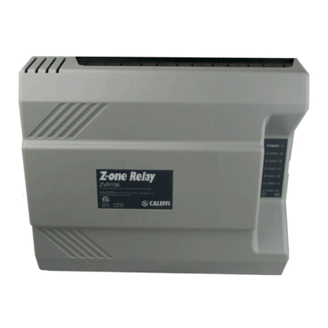
CALEFFI ThermoSetter 116 Series User guide
CALEFFI

CALEFFI ThermoSetter 116 Series User guide

CALEFFI 3048 Series User manual

CALEFFI

CALEFFI 3048 Series User manual

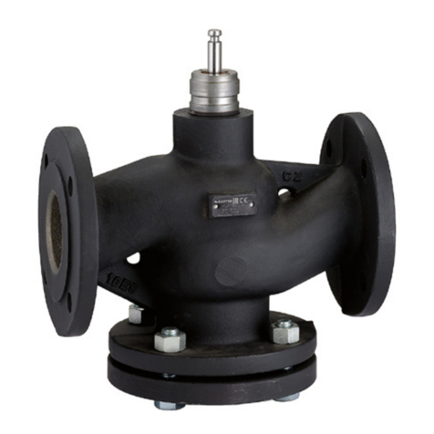
CALEFFI Z-one ZVR10 Series User manual
CALEFFI

CALEFFI Z-one ZVR10 Series User manual

Popular Control Unit manuals by other brands

JED JED T440 user manual

JED

JED JED T440 user manual

Dikkan DN15 operating instructions

Dikkan

Dikkan DN15 operating instructions

ICP DAS USA WF-2026 quick start

ICP DAS USA

ICP DAS USA WF-2026 quick start

Jung 2224 TSM operating instructions

Jung

Jung 2224 TSM operating instructions

Lantronix IONMM-232 install guide

Lantronix

Lantronix IONMM-232 install guide

Quectel BC26 manual

Quectel

Quectel BC26 manual

Digilent PmodBT2 manual

Digilent

Digilent PmodBT2 manual

Audiovox CS owner's manual

Audiovox

Audiovox CS owner's manual

Advantech PCM-3380 Startup manual

Advantech

Advantech PCM-3380 Startup manual

Hardinge 20C Instructions-parts list

Hardinge

Hardinge 20C Instructions-parts list

Siemens SINUMERIK 840D sl manual

Siemens

Siemens SINUMERIK 840D sl manual

Dometic Q3 Operation manual

Dometic

Dometic Q3 Operation manual

Genius INTERM0D02 433 manual

Genius

Genius INTERM0D02 433 manual

StepperOnline DM480AI user manual

StepperOnline

StepperOnline DM480AI user manual

Acromag AXM-A75 user manual

Acromag

Acromag AXM-A75 user manual

Staubli CombiTac direqt CTD-NET Assembly instructions

Staubli

Staubli CombiTac direqt CTD-NET Assembly instructions

herdstar BinTrac DBTB-200 installation manual

herdstar

herdstar BinTrac DBTB-200 installation manual

KEYBOARDPARTNER HX3.5 WiFi Module installation guide

KEYBOARDPARTNER

KEYBOARDPARTNER HX3.5 WiFi Module installation guide

manuals.online logo
manuals.online logoBrands
  • About & Mission
  • Contact us
  • Privacy Policy
  • Terms and Conditions

Copyright 2025 Manuals.Online. All Rights Reserved.