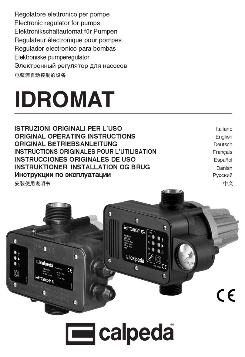
Calpeda IDROMAT User manual

Regolatore elettronico per pompe
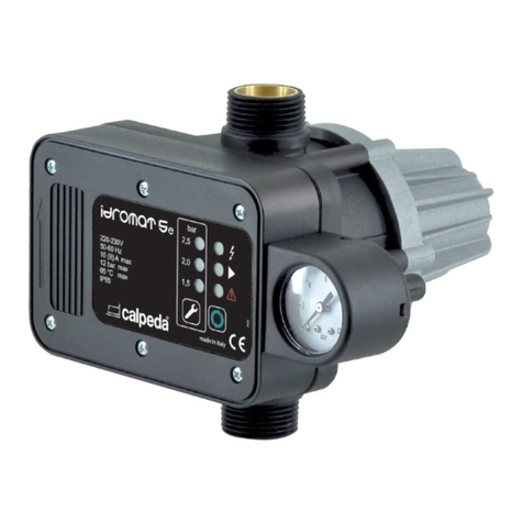
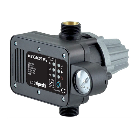
Electronic regulator for pumps
Elektronikschaltautomat fur Pumpen
Regulateur électonique pour pompes
Regulador electronico para bombas
Ηλεκτρονικός ελεγκτής για αντλίες
Электронный регулятор для насосов
IDROMAT
ISTRUZIONI ORIGINALI PER L'USO Pagina 2 Italiano
OPERATING INSTRUCTIONS Page 8 English
BETRIEBSANLEITUNG Seite 14 Deutsch
INSTRUCTIONS POUR L’UTILISATION Page 21 Français
INSTRUCCIONES DE USO Página 27 Español
INSTRUKTIONER INSTALLATION OG BRUG Side 33 Danish
ИНСТРУКЦИИ ПО ЭКСПЛУАТАЦИИ Страница 39 Русский
ISTR_IDROMAT_Rev02.indd 1ISTR_IDROMAT_Rev02.indd 1 03/03/22 14:3403/03/22 14:34

EN
Page 8 / 52 ISTR_IDROMAT_Rev02 - Operating Instructions
THIS INSTRUCTION MANUAL IS THE PROPERTY
OF Calpeda S.p.A. ANY REPRODUCTION, EVEN IF
PARTIAL, IS FORBIDDEN
INDEX
1. GENERAL INFORMATION .....................................8
2. TECHNICAL DESCRIPTION ..................................9
3. TECHNICAL FEATURES ........................................9
4. SAFETY ................................................................. 10
5. TRANSPORTATION AND HANDLING .............. 10
6. INSTALLATION .................................................... 11
7. STARTUP AND OPERATION .............................. 12
8. DISPOSAL ............................................................. 12
9. TROUBLESHOOTING .......................................... 13
CONNECTION DIAGRAMS ........................................ 46
GB. DECLARATION OF CONFORMITY .................... 50
1. GENERAL INFORMATION
Before using the product read carefully the information
contained in this instruction manual, the manual should
be kept for future reference.
Italian is the original language of this instruction
manual, this language is the reference language in
case of discrepancies in the translations.
This manual is part of the essential safety requirement
and must be retained until the product is nally
decommissioned.
The customer, in case of loss, can request a copy of
the manual by contacting Calpeda S.p.A. specifying the
type of product data shown on the label of the machine
!da duplicazione!
Any changes, alterations or modications made to the
product or part of it, not authorised by the manufacturer,
will revoke the “CE declaration” and warranty.
This appliance should not be operated
by children younger than 8 years,
people with reduced physical, sensory
or mental capacities, or inexperienced
people who are not familiar with the
product, unless they are given close
supervision or instructions on how to
use it safely and are made aware by a
responsible person of the dangers its
use might entail.
Children must not play with the
appliance.
It is the user's responsibility to clean
and maintain the appliance. Children
should never clean or maintain it
unless they are given supervision.
Do not use in ponds, tanks or
swimming pools or where people may
enter or come into contact with the
water.
1.1. Symbols
To improve the understanding of the manual, below are
indicated the symbols used with the related meaning.
Information and warnings that must be
observed, otherwise there is a risk that the
machine could damage or compromise
personnel safety.
The failure to observe electrical information
and warnings, could damage the machine or
compromise personnel safety.
Notes and warnings for the correct
management of the machine and its parts.
The failure to observe mechanical information
and warnings, could compromise personnel
safety.
The product surface can be extremely hot and
cause burns or injury to personnel.
The failure to observe mechanical information
and warnings, could compromise personnel
safety.
Operations that could be performed by the nal
user. After a careful reading of the instructions,
the nal user is responsible for maintenance
under normal conditions. The nal user is
authorised to affect standard maintenance
operations.
Operations that must be performed by a
qualied electrician specialised to affect all
electrical operations including maintenance
and able to operate with in the presence of high
voltages.
Operations that must be done by a qualied
technician able to install the device,
under normal conditions, working during
“maintenance”, and allowed to do mechanical
interventions for maintenance.
Indicates that it is mandatory to use individual
protection devices - protection for hands.
Indicates that it is mandatory to use individual
protection devices - protection for eyes.
Operations that must be done with the device
switched off and disconnected from the power
supply.
Operations that must be done with the device
switched on.
ISTR_IDROMAT_Rev02.indd 8ISTR_IDROMAT_Rev02.indd 8 03/03/22 14:3503/03/22 14:35
EN
ISTR_IDROMAT_Rev02 - Operating Instructions Page 9 / 52
1.2. Manufacturer name and address
Manufacturer name: Calpeda S.p.A.
Address: Via Roggia di Mezzo, 39
36050 Montorso Vicentino - Vicenza / Italia
www.calpeda.it
1.3. Authorised operators
The product is intended for use by expert operators
divided into end users and specialised technicians
(see the symbols above).
It is forbidden, for the end user, to carry
out operations which must be done only by
specialised technicians. The manufacturer
declines any liability for damage related to the
non-compliance of this warning.
1.4. Warranty
For the product warranty refer to the general terms and
conditions of sale.
The warranty covers only the replacement and
the repair of the defective parts of the goods
(recognised by the manufacturer).
The Warranty will not be considered in the following
cases:
1. Whenever the use of the device does not conform
to the instructions and information described in this
manual.
2. In case of changes or variations made without
authorization of the manufacturer.
3. In case of technical interventions executed by a
nonauthorised by the manufacturer personnel.
4. In case of failing to carry out adequate
maintenance.
1.5. Technical assistance
Any further information about the documentation,
technical assistance and spare parts, shall be
requested from manufacturer.
2. TECHNICAL DESCRIPTION
Pumps control device provided with ow rate and
pressure sensor The electronic controller IDROMAT
controls the automatic start and stop of the water
pump when opening or closing any tap or valve of
the installation. When the water pump starts, it keeps
running while there is any tap opened in the system,
giving the required ow at constant pressure to the
network.
Pump type Restart
pressure
Highest
plant point
Pump
head
IDROMAT 5-15 1,2 bar < 12 m > 25 m
IDROMAT 5-18 1,5 bar < 15 m > 30 m
IDROMAT 5-25 2,2 bar < 22 m > 35 m
IDROMAT 5-33 3,0 bar < 30 m > 45 m
IDROMAT 6-15 1,5 bar < 15 m > 30 m
IDROMAT 6-30 3,0 bar < 30 m > 45 m
IDROMAT 5e 1,5 bar < 15 m > 30 m
IDROMAT 5e 2,0 bar < 20 m > 35 m
IDROMAT 5e 2,5 bar < 25 m > 40 m
2.1. Intended use
For clean liquids, non-explosive or ammable, without
abrasives.
The electric control system can be used for
both potable and non-potable water. In case
of installations in which is possible to use the
two kinds of water, make sure that the potable
water circuit comes into contact with non-
potable water. (follow the laws in effect in the
Country in which the product is installed).
2.2. Uncorrect usage reasonally to forecast
The device is designed and built only for the purpose
described in (Paragraph 2.1).
Improper use of the device is forbidden, as
is use under conditions other than those
indicated in these instructions.
Improper use of the product reduces the safety and
the efciency of the device, Calpeda S.p.A. shall not
be responsible for failure or accident due to improper
use.
Do not use in ponds, tanks or swimming
pools or where people may enter or come into
contact with the water.
3. TECHNICAL FEATURES
3.1. Technical data
The device runs correctly only if all the following
features are respected.
Protection IP 65
Supply voltage/ Frequency:
115V 1~ ±10% (IDROMAT 5e not included)
230V 1~ ±10% 50/60Hz
Max. current value:
8 A IDROMAT 5
16 A IDROMAT 6
Working temperature: 0 ÷ + 65 °C
Max. working pressure: 12 bar
Relative Humidity: from 20 to 90% without
condensation
Maximum working rate: 10 m³/h (12 m³/h IDROMAT 6)
ISTR_IDROMAT_Rev02.indd 9ISTR_IDROMAT_Rev02.indd 9 03/03/22 14:3503/03/22 14:35

EN
Page 10 / 52 ISTR_IDROMAT_Rev02 - Operating Instructions
3.2. Construction
Inlet R1” male (R1” ¼ male for IDROMAT 6)
Outlet R1” male (R1” ¼ male for IDROMAT 6)
Special non return valve to prevent water hammering
Dry-running protection
Pressure gauge (IDROMAT 5-30 and 6. Not supplied)
Manual start switch (RESET )
Voltage LED (POWER )
Pump-running LED (ON )
Security system LED (FAILURE )
4. SAFETY
4.1. General provisions
Before using the product it is necessary to
know all the safety indications.
Carefully read all technical, operating instructions and
the indications dened in this manual for the different
steps: from transportation to disposal.
The specialised technicians must carefully comply
with all applicable standards and laws, including local
regulations of the country where the device is sold.
The device has been built in conformity with the current
safety laws.
The improper use could damage people, animals and
objects.
The manufacturer declines any liability in the event of
damage due to improper use or use under conditions
other than those indicated on the name-plate and in
these instructions.
Follow the routine maintenance schedules
and the promptly replace damaged parts,
this will allows the device to work in the best
conditions. Use only original spare parts
provided from Calpeda S.p.A. or from an
authorised distributor.
Do not remove or change the labels placed on
the device. Do not start the device in caseof
defects or damaged parts.
The device must never be opened, tampered
nor stripped of its protections.
The appliance must be installed, adjusted and
maintained by qualied personnel who understand the
risks involved.
Maintenance operations, requiring full or partial
disassembly of the device, must be done only
after disconnection from the supply.
All the power terminals and other terminals must be
inaccessible after installation is completed.
The connections of the alarms can distribute power
even when the the appliance is turned off.
Ensure that there is no residual voltage on the terminals
of the alarms.
4.2. Safety devices
The device has an external case that prevents any
contact with internal parts and the elements in voltage.
4.3. Residual risks
The appliance, designed for use, when used in-line with
the design and safety rules, does not have any residual
risk.
4.4. Individual protection devices
During installation, starting and maintenance it is
suggested to the authorised operators to consider
the use of individual protection devices suitable for
described activities.
5. TRANSPORTATION AND HANDLING
The product is packed to maintain the content intact.
During transportation avoid to stack excessive weights.
Ensure that during the transportation the box cannot
move.
It is not necessary to use any special vehicle to
transport the packaged device.
5.1. Handling
Handle with care, the packages must not receive
impacts.
Avoid to impact onto the package materials that could
damage the device.
The manufacturer disclaims any liability for use
under conditions other than those indicated in these
instructions.
5.2. Storing
The appliance should be stored in a dry place, protected
from shock and possibly with its original packaging.
The storage environment temperature must be from
-10°C up to +65°C.
ISTR_IDROMAT_Rev02.indd 10ISTR_IDROMAT_Rev02.indd 10 03/03/22 14:3503/03/22 14:35

EN
ISTR_IDROMAT_Rev02 - Operating Instructions Page 11 / 52
6. INSTALLATION
6.3. Ambient requirements and installation site
dimensions
The customer has to prepare the installation site in
order to guarantee the right installation and in order to
fulll the device requirements (electrical supply, etc...).
It is Absolutely forbidden to install the machine in an
environment with potentially explosive atmosphere.
6.4. Unpacking
Inspect the device in order to check any
damages which may have occurred during
transportation.
Package material, once removed, must be discarded/
recycled according to local laws of the destination
country.
6.5. Hydraulic connection
Before proceeding with hydraulic connection
make sure to prime the pump correctly.
The IDROMAT should always be installed in horizontal
position with the overmolded arrow pointing to the top,
connecting the inlet (male) directly to the pump and
the outlet (male) to the network (picture 1 chapter 10).
Do not locate the check valve at the on the exit
of the IDROMAT (picture 7). No device must
be installed between the pump and the device.
It is reccomended to apply a ball valve in the
outside of the device to isolate the IDROMAT
group pump from the net. (pictures 5-6).
It is advisable to connect the device outlet to the
system by using a hose. (picture 6)
Do not install the Idromat in systems with pumps
achieving more than 12 bar pressure at 0 ow.
The pressure created by the pump must be
normally 1 bar higher than the restarting
pressure of the device. In particular, the actual
pressure of pump and the height of water
column which burden on the device must be
checked in relation to the restarting pressure.
The head parameter must copmply with the
table in chapter 2.
6.6. Submersible pump installation
Install an auxiliary membrane tank with minimum
capacity of 20l to prevent exceeding the maximum
number of motor-startngs per hour. (picture 5) The
auxiliary tank must be swelled to a pressure of about
0,2 bar below the restarting IDROMAT pressure.
(chapter 10).
The pump does not have to operate at a ow
lower than the minimum ow indicated on the
pump plate.
6.7. Electric connection
Fasten the input/output cables by tightening the cable
gland ferrules in the lower part of the electric control
panel.
Electrical connection must be carried out only
by a qualied electrician in accordance with
local regulations.
Follow all safety standards.
The unit must be properly earthed (grounded).
Connect the earthing (grounding) conductor to the
terminal with the marking .
Once the electrical connection has been
completed, remove any pieces of wire, sheath,
washers or any other foreign bodies that may
be found inside the electric control panel.
Bad connections may spoil the electronic
circuit.
6.7.1. Power supply connection
Follow the indications reported in the electrical
scheme (paragraph 10).
6.7.2. Electric motor connection
For single-phase motors, the motor power
cable must be connected to the terminal block,
while for three-phase motors, the motor power
cable must be connected directly to the output
terminals of the contactor. (paragraph 10).
ISTR_IDROMAT_Rev02.indd 11ISTR_IDROMAT_Rev02.indd 11 03/03/22 14:3503/03/22 14:35

EN
Page 12 / 52 ISTR_IDROMAT_Rev02 - Operating Instructions
7. STARTUP AND OPERATION
7.1. Preliminary checks before start-up of the
pump
Do not start the device in case of damaged parts.
7.2. First starting
1. Be sure that the pump is correctly primed, then
gently open one tap
2. Connect the IDROMAT to the electric supply, the
voltage LED will lit (POWER ).
3. The pump starts working automatically and within a
period of 20-25 seconds the pressure gauge (only for
IDROMAT 5) will reach the maximum pump pressure.
While the pump is on, the led is lightened. If the
pump doesn't start or it doesn't reach the pressure,
reset with the button .
4. Close the tap indicated on point 1;after 8-10 seconds
the pump will stop. The voltage LED ( ) will be the
only one to remain on.
Any problem after this procedure will be due to a
defective pump priming.
7.3. Setting the restart pressure values (IDROMAT
5e)
The device is calibrated in factory to 1,5 bar, to change
the value keep the button Set pushed for 3 seconds for
one or more times. The green LED will light up next
to the value selected. The pump stops if the pressure
generated by the same fails to reach the values
indicated above. The pump restarts but does not start
working if the height of the water column is higher than
the quotas shown in the table at page 9).
7.4. Automatic restart and anti-jamming function
In case of stop due to a lack of aspiration water, the
device starts 10 double attempts of restart of about 5
seconds each one, during the next 24 hours from the
block. This to permit, if possible, the recharge of the
pump. After the last attempt of failed restart, the device
stays in alarm (red led FAILURE intermittent) waiting
for a new manual restart through the pushbutton
(RESET ). In case the pump will be stopped for 24
consecutive hour (except in presence of FAILURE
) the device restarts the motor automatically of about
5 seconds (antiblockage function). In case of energy
interruption, the device restarts automatically at the
energy return.
7.5. Switch off
The device must be switched off every time
there are faults.
The device is designed for continuous working. The
shutdown takes place only disconnecting the power
supply according to the specic disconnection
methods. (Paragraph 6.7).
8. DISPOSAL
Dir. 2012/19 EU (WEEE)
Observe the local regulations and dispose of any
control gear accordingly.
This product contains electrical and electronic
components and should be disposed accordingly.
Separate the components using anti-cut water
resistant gloves.
Is preferred to help to make a further use or dismantling.
Observe the local regulations and dispose the device
accordingly with the international rules for environment
protection.
ISTR_IDROMAT_Rev02.indd 12ISTR_IDROMAT_Rev02.indd 12 03/03/22 14:3503/03/22 14:35

EN
ISTR_IDROMAT_Rev02 - Operating Instructions Page 13 / 52
9. TROUBLESHOOTING
Before doing any troubleshooting on the appliance, it is necessary to disconnect any supply for at least 5 minutes.
Be sure that the main supply cannot be accidentally turned on.
(General issues)
PROBLEM PROBABLE CAUSES POSSIBLE REMEDIES
The pump does
not stop
Water loose greater than 1l/min through
the tube.
Check the closure of the valves involved.
Manual button of starting (RESET)
blocked.
Act on the button many times, in case of
anomaly persistence, contact the technical
service.
Failure in the electronic card. Replace the circuit board.
The pump does
not start
No electrical supply. Check the proper electric feeding. The voltage
LED (POWER ) should be on.
Not enough water supply, the security
system has been activated and the LED
(FAILURE ) is on.
Check the water supply and reset the pump
through the reset switch (RESET ).
Pump is blocked: LED (FAILURE ) is on,
the security system is activated.
When you act on the manual start switch
(RESET ) the LED (ON) is activated but the
pump does not work: contact your dealer.
Failure in the electronic card. Replace the circuit board.
Not enough pump pressure: the security
system has been activated and the
corresponding LED (FAILURE ) is on.
Make sure that the pump pressure is higher
than the starting IDROMAT pressure and that
the highest point of the plant is lower than the
value reported on the technical table.
Air in the pump suction: the pressure
gauge will indicate a pressure lower than
the nominal one or constant oscillations.
The security system will act by stopping the
pump, the LED (FAILURE) will be on.
The pump
starts and stops
repeatedly
Small leakage in some point of the
installation.
Check if there is a leakage from the tap or
water closet, and x them. If the system does
not reach the restarting pressure, the FAILURE
led ashes.
Subject to modication.
ISTR_IDROMAT_Rev02.indd 13ISTR_IDROMAT_Rev02.indd 13 03/03/22 14:3503/03/22 14:35

46 / 52 ISTR_IDROMAT_Rev02
10. SCHEMI DI COLLEGAMENTO
CONNECTION DIAGRAMS
ANSCHLUßPLÄNE WEITER UNTEN
SCHEMA DE RACCORDEMENT
ESQUEMAS DE CONEXION
TILSLUTNINGS DIAGRAMMER
ΣΧΕΔΙΑΓΡΑΜΜΑΣΥΝΔΕΣΗΣ
СХЕМЫДЛЯПОДКЛЮЧЕНИЯ
DIMENSIONI
Figura 1
188
140
R1”
R1”
98
150,5
190
60
88 52
130
IDROMA
T 5
Figura 2
R 1" 1/4
66 185
251
R 1" 1/4 60 151
211
175
110V÷240V
65 °C max
50/60 Hz IP 65
30 (16) A max 12 bar max
P607.a- REV00
Made in Italy
P607.b-REV00
IDROMA
T 6
ISTR_IDROMAT_Rev02.indd 46ISTR_IDROMAT_Rev02.indd 46 03/03/22 14:3503/03/22 14:35

ISTR_IDROMAT_Rev02 47 / 52
Figura 3 Figura 4
IDROMAT 5-15: max 15 m
IDROMAT 5-12: max 12 m
IDROMAT 5-22: max 22 m
IDROMAT 6-15: max 15 m
IDROMAT 5-30: max 30 m
IDROMAT 6-30: max 30 m
4.93.096/14
Valvola di non ritorno
Check valve
Clapet de non-retour
Valvula de retencion
Funzionamento sotto battente
Positive suction head operation
Fonctionnement en charge
Funcionamiento bajo carga
Funzionamento in aspirazione
Suction lift operation
Fonctionnement en aspiration
Funcionamiento en aspiración
4.93.096
IDROMAT 5-15: max 15 m
IDROMAT 5-12: max 12 m
IDROMAT 5-22: max 22 m
IDROMAT 6-15: max 15 m
IDROMAT 5-30: max 30 m
IDROMAT 6-30: max 30 m
Valvola di non ritorno
Check valve
Clapet de non-retour
Valvula de retencion
Figura 5 Figura 6 Figura 7
20l
ISTR_IDROMAT_Rev02.indd 47ISTR_IDROMAT_Rev02.indd 47 03/03/22 14:3503/03/22 14:35

48 / 52 ISTR_IDROMAT_Rev02
Figura 8
0,5 m
h
G 1 DN 25
(Øi 28 mm)
G 1 1/4 DN 32
(Øi 36 mm)
MXA 205,405
Hs
404204
100
200
450
600
-
203
100
200
450
600
-
Hs
(m)
≤
2
4
6
8
9
405
100
450
600
600
-
500
500
600
600
-
h (mm)
205
500
500
500
600
-
403
100
450
600
600
-
NGL
500
500
500
500
500
500
500
500
500
500
NGX
MXA
0
Valvola di non ritorno
Check valve
Clapet de non-retour
Valvula de retencion
MXA, NGX, NGL
Capacità di autoadescamento
Self-priming capability
Capacitè d’autoamorçage
Capacidad de autoaspiraciòn
H2O, T = 20°C
Pa = 1000 hPa (mbar)
50 Hz (n ≈ 2800 1/min)
Per i 60 Hz vedere i dati tecnici.
Hs (m) = Altezza di aspirazione
t (min) = Tempo di autoadescamento
ISTR_IDROMAT_Rev02.indd 48ISTR_IDROMAT_Rev02.indd 48 03/03/22 14:3503/03/22 14:35

ISTR_IDROMAT_Rev02 49 / 52
Figura 9
L
N
1 ~
L
N
U
V
M
115 V 50-60Hz
230 V 50-60Hz
115 V 50-60Hz
230 V 50-60Hz
Figura 10
M
L
N
Contactor
1 ~
L
N
U
V
115 V 50-60Hz > 0,75 kW
230 V 50-60Hz > 1,5 kW
115 V 50-60Hz
230 V 50-60Hz
Figura 11
L 1
L 2
L 3
N
M
Contactor
3 ~
L
N
U
V
400 V 50-60Hz
230 V
400 V 50-60Hz
ISTR_IDROMAT_Rev02.indd 49ISTR_IDROMAT_Rev02.indd 49 03/03/22 14:3503/03/22 14:35

50 / 52 ISTR_IDROMAT_Rev02
IT. DICHIARAZIONE DI CONFORMITÀ
Noi Calpeda S.p.A. dichiariamo sotto la nostra esclusiva responsabilità che il prodotto IDROMAT, tipo e numero
di serie riportati in targa, sono conformi a quanto prescritto dalle Direttive 2011/65/EU, 2014/30/EU, 2014/35/EU
e dalle relative norme armonizzate.
GB. DECLARATION OF CONFORMITY
We CALPEDA S.p.A. declare that the product IDROMAT, with type and serial number as shown on the name
plate, are constructed in accordance with Directives 2011/65/EU, 2014/30/EU, 2014/35/EU and assume full
responsability for conformity with the standards laid down therein.
DE. KONFORMITÄTSERKLÄRUNG
Wir, das Unternehmen CALPEDA S.p.A., erklären hiermit verbindlich, daß das Produkt IDROMAT, Typbezeichnung
und Fabrik-Nr. nach Leistungsschild den EG-Vorschriften 2011/65/EU, 2014/30/EU, 2014/35/EU entsprechen.
F. DÉCLARATION DE CONFORMITE
Nous, CALPEDA S.p.A., déclarons que le produit IDROMAT, modèle et numero de série marqués sur la plaque
signalétique sont conformes aux Directives 2011/65/EU, 2014/30/EU, 2014/35/EU.
ES. DECLARACION DE CONFORMIDAD
En CALPEDA S.p.A. declaramos bajo nuestra exclusiva responsabilidad que el producto IDROMAT, modelo y
numero de serie marcados en la placa de caracteristicas son conformes a las disposiciones de las Directivas
2011/65/EU, 2014/30/EU, 2014/35/EU.
DK. OVERENSSTEMMELSESERKLÆRING
Vi CALPEDA S.p.A. erklærer, at nedenstående produkt IDROMAT, type og serie nummer vist på typeskiltet er
fremstillet i overensstemmelse med bestemmelserne i Direktiv 2011/65/EU, 2014/30/EU, 2014/35/EU og er i
overensstemmelse med de heri indeholdte standarder.
NL. CONFORMITEITSVERKLARING
Wij CALPEDA S.p.A. verklaren hiermede dat het product IDROMAT, type en serienummer zoals vermeld op de
typeplaat aan de EG-voorschriften 2011/65/EU, 2014/30/EU, 2014/35/EU voldoen.
SV. EU NORM CERTIFIKAT
CALPEDA S.p.A. intygar att produkterna IDROMAT, typ och serienummer, visade på namnplåten är konstruerade
enligt direktiv 2011/65/EU, 2014/30/EU, 2014/35/EU. Calpeda åtar sig fullt ansvar för överensstämmelse med
standard som fastställts i dessa avtal.
GR.ΔΗΛΩΣΗΣΥΜΦΩΝΙΑΣ
Εμείς ως CALPEDA S.p.A. δηλώνουμε με αποκλειστικά δική μας ευθύνη ότι τα προιόντα IDROMAT, , με τύπο
και αριθμό σειράς κατασκευής όπου αναγράφετε στην πινακίδα της αντλίας, κατασκευάζονται σύμφωνα με
τις οδηγίες 2011/65/EU, 2014/30/EU, 2014/35/EU, και αναλαμβάνουμε πλήρη υπευθυνότητα για συμφωνία
(συμμόρφωση), με τα στάνταρς των προδιαγραφών αυτών.
RU.ДЕКЛАРАЦИЯСООТВЕТСТВИЯ
Компания Calpeda S.p.A. заявляет с полной ответственностью, что изделия IDROMAT, тип и серийный
номер которых указывается на заводской табличке соответствуют требованиям нормативов 2011/65/
EU, 2014/30/EU, 2014/35/EU.
Montorso Vicentino, 03/2022
CALPEDA S.p.A.
Il Presidente
Marco Mettifogo
ISTR_IDROMAT_Rev02.indd 50ISTR_IDROMAT_Rev02.indd 50 03/03/22 14:3503/03/22 14:35

ISTR_IDROMAT_Rev02 51 / 52
UK DECLARATION OF CONFORMITY
Manufacturer’s Name: Calpeda S.P.A.
Address: Via Roggia di Mezzo 39, 36050 Montorso Vicentino (VI) Italy
We Calpeda S.P.A. declare that:
the undersigned company certies under its sole responsibility that the pumps specied below satisfy the
following requirements of UK regulations.
Products Models : IDROMAT
UK Regulations:
Supply of Machinery (Safety) Regulations 2008
Electrical Equipment (Safety) Regulations 2016
Electromagnetic Compatibility Regulations 2016
The Restriction of the Use of Certain Hazardous Substances in Electrical and Electronic Equipment Regulations
2012
Applicable designated standards:
BS ISO 12100:2010; BS 809:1998+A1:2009
BS 60335-1:2012/A2:2019; BS 60335-2-41:2003/A2:2010
BS 55014-1:2017; BS 55014-2:2015; BS 61000-3-2:2014; BS 61000-3-3:2013/A1:2019
Personauthorisedtocompilethetechnicalle:
Mettifogo Marco
Calpeda S.p.A.
Via Roggia di Mezzo 39, 36050 Montorso Vicentino (VI) Italy
Montorso Vicentino - Italy – 02 March 2022
CALPEDA S.p.A.
Il Presidente
Marco Mettifogo
ISTR_IDROMAT_Rev02.indd 51ISTR_IDROMAT_Rev02.indd 51 03/03/22 14:3503/03/22 14:35

Calpeda s.p.a. - Via Roggia di Mezzo, 39 - 36050 Montorso Vicentino - Vicenza / Italia
Tel. +39 0444 476476 - Fax +39 0444 476477 - E.mail: [email protected] www.calpeda.com
ISTR_IDROMAT_Rev02.indd 52ISTR_IDROMAT_Rev02.indd 52 03/03/22 14:3503/03/22 14:35
Other manuals for IDROMAT
1
Table of contents
Other Calpeda Controllers manuals

Calpeda
Calpeda M COMP 4-16 User manual

Calpeda
Calpeda Easymat User manual

Calpeda
Calpeda IDROMAT Series User manual

Calpeda
Calpeda IDROMAT User manual

Calpeda
Calpeda PFC-T User manual

Calpeda
Calpeda IDROMAT 5 User manual

Calpeda
Calpeda IDROMAT 5 User manual

Calpeda
Calpeda IDROMAT 3 User manual

Calpeda
Calpeda PFC-M Series User manual
Popular Controllers manuals by other brands

Mitsubishi Electric
Mitsubishi Electric GB-24A Instruction book

Unitronics
Unitronics Vision OPLC V1040-T20B user guide

Tech Controllers
Tech Controllers EU-WIFI L user manual

GEIGER
GEIGER GFU003 operating instructions

ICM Controls
ICM Controls ICM2909 quick start guide

Di-soric
Di-soric BC-100-20A operating manual