Calsense 500 Series Operating instructions

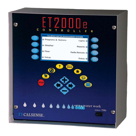
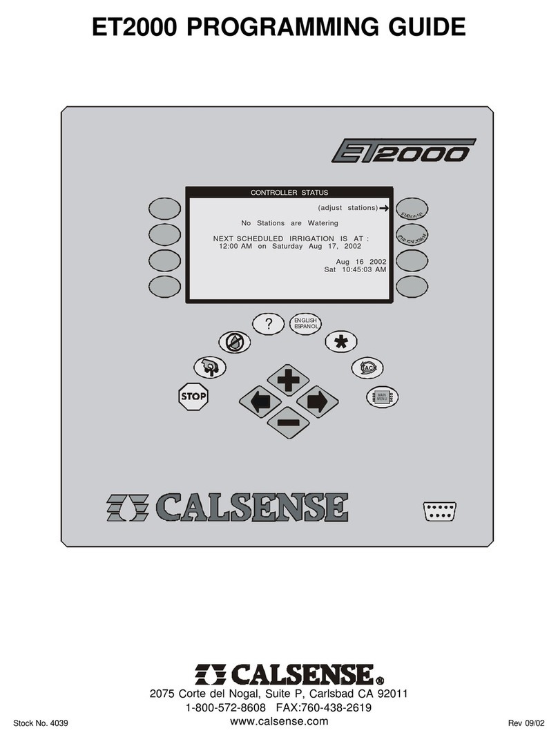
® ET2000 (500 SERIES) PROGRAMMING GUIDE
making
since 1986
w
ater work
ET2000 (500 SERIES)
IRRIGATION CONTROLLER
PROGRAMMING GUIDE

TABLE OF CONTENTS ®
making
since 1986
w
ater work
TABLE OF CONTENTS
SECTION 1: CONTROLLER DESCRIPTION
I. ET2000 KEY PAD DESCRIPTION
II. WHAT CAN BE PROGRAMMED AT EACH
SCREEN
III. USING THIS GUIDE WITH THE ET2000
CONTROLLER
SECTION 2: SETUP
A. COMMUNICATIONS
1. CONTROLLER(S) WITH CENTRAL
COMMUNICATION
B. PART & SERIAL NUMBER
C. DATE & TIME
D. STATIONS IN USE
E. 12-MONTH MODE
F. ACCESS CONTROL
SECTION 3: PROGRAMS & STATIONS
A. START TIMES AND WATER DAYS
B. STATIONS (STATION PROGRAMMING)
1. CYCLE AND SOAK EXAMPLES
2. TEST A STATION AT THE STATION
PROGRAMMING SCREEN
3. SET NO WATER DAYS AT THE
STATION PROGRAMMING SCREEN
C. STATION TO STATION COPY
1. COPY A STATION TO ANOTHER
STATION
2. COPY A STATION TO ALL STATIONS
ON A PROGRAM, OR ALL STATIONS
ON THE CONTROLLER
D. STATIONS BY PROGRAM
SECTION 4: FLOW
A. FLOW METER SETUP
1. ESTIMATED WATER USAGE
2. FMBX FLOW METER SETUP
3. REGULAR FLOW METER SETUP
4. LEARN EXPECTEDS (FLOW RATE)
B. LINE FILL & VALVE CLOSE TIMES
C. MASTER VALVE
D. PUMP
E. MAIN LINE CAPACITY
F. ON-AT-A-TIME
G. FLOW CHECKING
H. ALERT ACTIONS
SECTION 5: WEATHER
A. ET GAGE (-G OPTION)
1. ET GAGE SETUP
B. RAIN BUCKET (-RB OPTION)
1. RAIN SETUP (WITH RAIN BUCKET
INSTALLED)
2. RAIN SETUP (WITHOUT RAIN
BUCKET INSTALLED) AND YOU ARE
SHARING RAIN TO CONTROLLER
C. WIND GAGE (-WG OPTION)
1. WIND GAGE SETUP
2. RESPOND TO WIND BY PROGRAM
D. RAIN SWITCH
1. RAIN SWITCH SETUP
E. ET
1. IRRIGATE USING ET TABLE
2. USE ET AVERAGING
3. ALLOWABLE % OF HISTORICAL ET
4. CROP COEFFICIENTS
5. STATION FLOW RATES WITHOUT A
FLOW METER PRESENT
6. STATION FLOW RATES & AREA WITH
FLOW METER INSTALLED
F. BUDGET
1. DIRECTLY ENTER THE MONTHLY
BUDGETS
2. CONTROLLER WILL
AUTOMATICALLY CALCULATE THE
BUDGET AMOUNT USING THE
TOTAL SQUARE FOOTAGE AND
YOUR CITY ET
3. ENTER A YEARLY BUDGET AND
HAVE THE CONTROLLER DIVIDE IT
AMONG THE MONTHS USING YOUR
CITY ET

® TABLE OF CONTENTS
making
since 1986
w
ater work
G. MOISTURE
1. MOISTURE SENSOR SETUP
2. MOISTURE SENSOR ASSIGNMENT
3. TEST MOISTURE SENSOR
H. ET COUNTY / CITY
1. ET COUNTY / CITY SETUP
SECTION 6: REPORTS
A. THIS MONTH / LAST MONTH
B. 24 MONTH
C. HOLD-OVER
D. ET AND RAIN TABLES
1. REPORTS / ET & RAIN TABLE (ET)
2. REPORTS / ET & RAIN TABLE (RAIN)
E. ALERTS
F. STATION HISTORY
G. USE VS. BUDGET
H. LIVE SCREENS
1. IRRIGATION ACTIVITY
2. IRRIGATION DETAILS
3. REAL-TIME FLOW
SECTION 7: LIGHTS (-L OPTION)
A. PROGRAMMING A LIGHTS SCHEDULE
B. TESTING A LIGHTS CIRCUIT
SECTION 8: RADIO REMOTE (-RR OPTION)
A. ENABLE RADIO REMOTE
SECTION 9: NO WATER KEY
A. NO WATER KEY DESCRIPTION
1. TURN CONTROLLER OFF
2. APPLY NO WATER DAYS TO
PROGRAM
3. NO WATER DAYS BY STATION
SECTION 10: MANUAL KEY
A. MANUAL WATERING
1. MANUAL WATER A STATION
2. MANUAL WATER A PROGRAM
3. CYCLE AND SOAK DURING
MANUAL
B. TEST
1. LEARN THE EXPECTED (FLOW
RATE) AT A STATION
2. TEST A STATION
3. TEST A STATION MOISTURE
SENSOR (see SECTION 5
MOISTURE)
C. MV (MASTER VALVE) OVERRIDE
1. OPEN MASTER VALVE FOR
SPECIFIED TIME
2. WEEKLY SCHEDULE FOR
OPENING MASTER VALVE
D. LEARN EXPECTEDS (FLOW RATE)
E. MANUAL PROGRAM 1
F. MANUAL PROGRAM 2 (see MANUAL
PROGRAM 1)
G. WALK THRU
H. USE HOLD OVER
SECTION 11: FLOWSENSE®(-FL OPTION)
A. MULTIPLE CONTROLLER COMMUNICATION
SETUP
B. MULTIPLE CONTROLLER FLOW SETUP
1. MAINLINE CAPACITY
2. FLOW CHECKING
3. ON-AT-A-TIME
SECTION 12: (-F OPTION)
A. MULTIPLE FLOW METER SETUP
1. FMBX FLOW METER SETUP
2. REGULAR FLOW METER SETUP
3. LEARN EXPECTEDS (FLOW
RATES)
ENCLOSURES
1. ET2000 IRRIGATION CONTROLLER SCREEN
MAP
2. FLAG LETTER DEFINITION SHEET

SECTION 1 / I. ET2000 KEY PAD DESCRIPTION ®
making
since 1986
w
ater work
SECTION 1 CONTROLLER DESCRIPTION
I. ET2000 KEY PAD DESCRIPTION
1
10 9
8
4
8
5
6
7
3
2
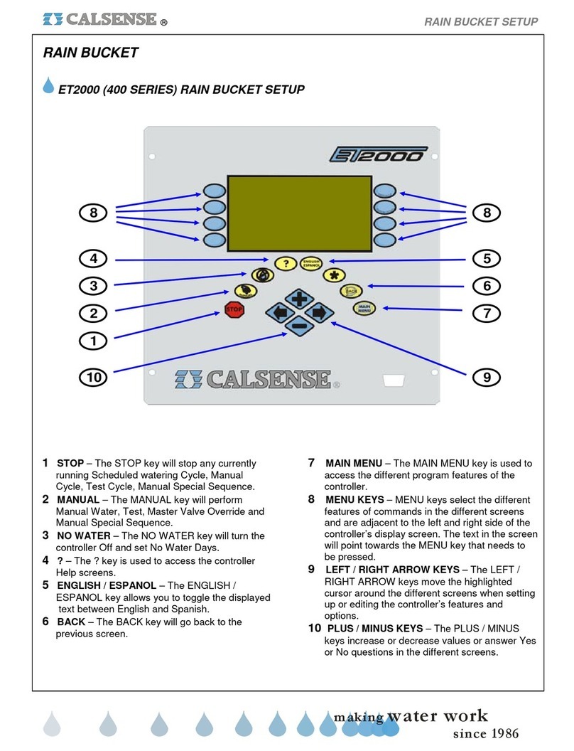
1STOP – The STOP key will stop any currently
running Scheduled watering Cycle, Manual
Cycle, Test Cycle, Manual Programs.
2MANUAL – The MANUAL key will perform
Manual Water, Test, Master Valve Override,
Manual Program 1 & 2, Walk-thru, and
Use Hold-over.
3NO WATER – The NO WATER key is used for
turning the controller Off and to set No Water
Days.
4?– The ? key is used to access the controller
Help screens.
5ENGLISH / ESPANOL – The ENGLISH /
ESPANOL key allows you to toggle
the displayed
text between English and Spanish.
6BACK – The BACK key will go back to the
previous screen.
7MAIN MENU – The MAIN MENU key is used to
access the different program features of the
controller.
8MENU KEYS – MENU keys are used to select
the different features of commands in the
various screens. The text in the screen will point
towards the MENU key that needs to be
pressed.
9LEFT / RIGHT ARROW KEYS – The LEFT /
RIGHT ARROW keys move the highlighted
cursor around the different screens when
setting up or editing the controller’s
features and options.
10 PLUS / MINUS KEYS – The PLUS / MINUS
keys are used to increase or decrease values
or answer Yes or No questions in the different
screens.

® SECTION 1 / II. WHAT CAN BE PROGRAMMED AT EACH SCREEN
making
since 1986
w
ater work
Programs & Stations
Select Program
Set Program Start Time
Select Program Description (optional)
Set Number Of Water Days inSchedule
Set Water Days
Set Program Stop Time (optional)
If 12 Month Schedule Is Enabled:
Set All The Above For Each Month Of The Year
Select Stop Time
If Not In DailyET Mode:
Set Station Program Assignment
Set Total Minutes
Set Minutes Per Cycle
Set Soak-In-Time
Set No Water Days
Test Station
If In DailyET Mode:
Set Station Program Assignment
Set % ET
Set Minutes Per Cycle
Set Area (Sq. Ft.)
Set No Water Days
Test Station
Copy Station-To-Station
Copy Station-To-Program
View Station By Program
Move Station From Program To Program
Programs & Stations
Start Times & Water
Days
Station
Programming
Station-To-Station
Copy
Station-By-Program
Weather
Select Irrigation Day Window
Select To Use ET Gage
Select To Log Et Pulses
Reset Full ET Gage
Manually Set Gage Amount In Inches
Set Skip Tonight
Set Minimum Rain
Set Maximum Hourly Rain
Set Maximum 24 Hour Rain
Set Maximum Total Rain
Set Use Of Rain By Program
Select The Use Of Wind Gage
Set Wind Speed For Pausing Irrigation
Set Wind Speed to Resume Irrigation
Respond To Wind By Program
Rain Switch Select To Use A Rain Switch Device
Select To Use Daily ET (By Program)
ET Select To Use ET Averaging (By Program)
Crop Coefficients In Use Setting
Select To Use A Budget
Select Budget By Square Footage
Budget Select Budget By City ET
Select Budget By Monthly Direct Enter
Calculate Budget
Select To Use Moisture Sensors
Assign Sensor Slaving To Valves
Select County And City For ET
Enter Your Own ET Numbers
View Historical ET Totals
Moisture
ET County / City
Weather
ET Gage
Rain Bucket
Wind Gage
Flow
Line Fill By Program
Valve Close By Program
Set High Flow Alert Actions By Program
Alert Actions Set Low Flow Alert Actions By Program
Master Valve Select Type Of Master Valve
Pump Select Use Of Pump (By Program)
Select To Use A Flow Meter
Select To Use List Or Enter Own Parameters
Set Flow Meter Size / Set Own parameters
Learn Expecteds By Program
Set Mainline Break Numbers
Set System Maximum Flow Rates
Set Valves On At A Time Within Program
Set Valves On At A Time Within
Controller / System (IF More Than One Controller)
Line Fill & Valve
Close Times
Flow Meter
Mainline Capacity
Flow
On-At-A-Time
Manual Programs
Manual Water A Station
Manual Water A Program
Cycle And Soak During Manual
Learn The Expected At A Station
Test
Test Station
Test Station Moisture Sensor
Open Master Valve For Hours
Weekly Schedule For Opening Master Valve
Learn Expected
Learn The Expected By Program
Schedule Water Days For Manual Program 1
Set Up To 6 Start Times For Manual Program 1
Set Run Duration From / To
Set Station Times
Schedule Water Days For Manual Program 2
Set Up To 6 Start Times For Manual Program 2
Set Run Duration From / To
Set Station Times
Set Walk Thru Count Down
Set Station Run Times
Set Walk-Thru Station Order
Begin Countdown
Select Use Hold-Over
Set Start Times For Hold-Over Use
Set Stop Time For Hold-Over Use
Select Water Days For Hold-Over
Use Hold-Over
Manual Programs
Manual Water
Manual Program 1
Master Valve
Override
Manual Program 2
Walk-Thru

SECTION 1 / II. WHAT CAN BE PROGRAMMED AT EACH SCREEN ®
making
since 1986
w
ater work
Setup
Select If Part Of FLOWSENSE® Chain
Select Number Of Controllers In Chain
Set Communications Address
View Controller Information
View R.O.M. Version
View Controller Baud Rate
View Part Number
View Serial Number
View CC4 Version Required
View Expected Communication Signal Levels
View Current Date & Time
Date & Time Change Date & Time
Use Day Light Savings Time
Select To Activate AStation
Select To Deactivate A Station
12 Month Mode Turn On Twelve Month Mode
View Current Access Level
Enter Your Access Code
Setup
Communications
Part & Serial
Number
Stations In Use
Access Control
Miscellaneous
Set Up Four Separate Lights Schedules
Manually Start Lights For 4 hours
Radio Remote Enable Radio Remote
Station Alerts View And Clear Station Alerts
Controller Alerts View And Clear Controller Alerts
View Current Status Of Controller
Status View Next Scheduled Irrigation
Turn Controller ON (If It Has Been Turned OFF)
Miscellaneous
Lights
Reports
View Water Usage And Irrigation Time
24 Month View Yearly Water Usage & Budget Totals
View Station Hold-Over
Clear All Hold-Over
Clear Station Hold-Over
View Or Edit ET Tables
View Rain Table
Alerts View Controller Alerts
Station History View Station History
Use Vs. Budget View Actual & Expected Water Usage
Compared To Budget
View Irrigation Activity
View Irrigation Details
View Real-Time Flow
Reports
This Month / Last
Month
Hold-Over
ET & Rain Tables
Live Screens
No Water
Turn Controller OFF
Apply No Water Days To Program
No Water Days By Station
No Water
No Water

® SECTION 1 / III. USING THIS GUIDE WITH THE ET2000 CONTROLLER
making
since 1986
w
ater work
III. USING THIS GUIDE WITH THE ET2000 CONTROLLER
This guide will explain the operation and programming of the ET2000 Controller. The following describes the
conventions used throughout this guide. When instructed to press a key, the name of the key will be
CAPITALIZED AND BOLD. The illustration below shows the name and location of keys used for operating and
programming the ET2000 Controller.
MENU KEYS: The eight (8) blue keys located on either side of the controller screen. The text next to the key
indicates the choice available and will change with each screen. The arrow will point to the Menu key that is to be
pressed, and the name of the key will be CAPITALIZED AND BOLD.
HOT KEYS: The eight (8) keys in a horseshoe shape directly below the display screen. They are the STOP,
MANUAL, NO WATER, HELP, ENGLISH / SPANISH, BACK, and MAIN MENU key.
PLUS / MINUS & ARROW KEYS: The last four (4) keys are the PLUS key, MINUS key and the two (2) ARROW
keys. When a screen is accessed, certain information on the screen can be changed. There will be a highlighted
cursor on the screen, which you can move with either ARROW key. A change can only be made to a setting while
it is highlighted by the cursor. Once a setting is highlighted, use the PLUS or MINUS key to make the change. If
the setting is a number, you can quickly scroll to the desired setting by holding down the PLUS or MINUS key.
The Controller’s screen in the illustration below shows the Main Menu, which can be accessed at any time by
pressing the MAIN MENU key. The description on the screen with the arrows, point to the Menu keys which can
be pressed to access the various parts of the controller’s programming (See Enclosure 1 ET2000 IRRIGATION
CONTROLLER SCREEN MAP). You can always return to a previous screen by pressing the BACK key.
Station UP key
Station DOWN key
ET2000 Irrigation Controller Key Placement and Description
Help key
Manual key
No Water key
Arrow key
Stop key
Month UP key
Month DOWN key
Menu keys
Weather Reports
Menu Keys
MenuKey Name Controller Screen Showing Main Menu
Setup Status
Flow Radio Remote
CALSENSE WATER MANAGEMENT SYSTEM
Programs & Stations Lights
English /
Spanish key
Plus or Minus key
Main Menu key
Back key
Star key

SECTION 2 SETUP ®
making
since 1986
w
ater work
SECTION 2: SETUP
The Setup section of the controller is used for
programming the following:
•Communication addresses
•Accessing the controller’s Part & Serial
number information
•Setting Time & Date
•Activating stations in use
•Utilizing a 12 month schedule
•Inputting access codes
A. COMMUNICATIONS
Skip communication setup section if controller(s) has
no communications option installed.
The Communications screen can be used to set the
communications address in the controller. This
address is used for communicating back to a central
computer, and is also used to differentiate one
controller from another in a communications chain.
From the MAIN MENU screen.
1. Press the SETUP Menu key.
The GENERAL SETUP screen is displayed
(Figure 2.1).
ET2000-40 -MSR-RR
(
576.i
)
Communication 12 Month Mode
Part & Serial Numbers
Stations In Use Access Control
Date & Time
Figure 2.1
2. Press the COMMUNICATION Menu
key, the COMMUNICATION screen
will appear.
1. Controller(s) with central communication:
Note: If FLOWSENSE®option is installed (This can
be verified by looking for a (-FL) in the part number
of the controller section 1B) See Section 11 for
detailed instructions.
The communication screen should look like the one
in Figure 2.2 if your controller does not have the
FLOWSENSE®option.
Controller Info
Communications Address: ! !A
controllers is not availible.
ET-40-MSR-RR
(
576.i
)
FLOWSENSE irrigation between multiple
This is not a -FL controller.
Figure 2.2
1. Press the blue ARROW keys to
highlight the Communications address.
2. Press the PLUS or MINUS keys to
set the first character.
3. Press the blue ARROW keys to move
the cursor to the next character.
Repeat the process described above until all three
characters are set (The character furthest to the right
must be a letter).
Note: With multiple controllers one of the controllers
must be the Master with an address ending in a
Capitol “A”. All other controllers will have addresses
ending in B, C, D, etc. No two controllers can have
the same exact address when communicating to the
same central computer. The Master controller must
be the controller communicating back to the central.
To view the controller’s communications
information:
4. Press the CONTROLLER INFO
Menu key.
The PART & SERIAL NUMBERS screen is
displayed (Figure 2.3).
PART & SERIAL NUMBERS
ET2000-40-MSR-RR
576.i s=6 c=6 A=14400 B=14400
Serial Num: 00000 CC4 Ver: 4.0.11.26
(the normally expected signal levels)
RTS CTS DTR DSR CD RI
A
: L L L L L L
B: L L L L L L
Copyright Calsense Inc. 1987-2005
All Rights Reserved
(use * Key for special menu)
Figure 2.3
THIS CONCLUDES THE COMMUNICATIONS
SECTION

® SECTION 2 SETUP
making
since 1986
w
ater work
B. PART & SERIAL NUMBER
This screen contains part & serial number
information along with communication information for
the controller.
From the MAIN MENU screen.
1. Press the SETUP Menu key.
2. Press the PART & SERIAL NUMBERS
Menu key.
The PART & SERIAL NUMBERS screen is
displayed (Figure 2.4).
Copyright Calsense Inc. 1987-2005
All Rights Reserved
(use * Key for special menu)
RTS CTS DTR DSR CD RI
A: L L L L L L
B: L L L L L L
Serial Num: 12345 CC4 Ver: 4.0.11.26
(the normally expected signal levels)
PART & SERIAL NUMBERS
ET2000-40-MSR-RR
576.i s=6 c=6 A=14400 B=14400
Figure 2.4
THIS CONCLUDES THE PART A& SERIAL
NUMBER SECTION
C. DATE & TIME
The Date & Time setting on a new controller will be
set to Pacific Standard Time and will need to be
changed to the local time by the customer upon
receipt.
From the MAIN MENU screen.
1. Press the SETUP Menu key.
2. Press the DATE & TIME Menu key.
The DATE AND TIME screen is displayed
(Figure 2.5).
DATE & TIME
Current Date & Time :
Oct 28 2005, Fri 10:49:49AM
Date & Time to Set:
PUSH here to SET IT
Use Day Light Savings? YES
Figure 2.5
3. Press the PLUS or MINUS keys to
change the Month setting.
4. Press the blue ARROW keys to move
the cursor to the next entry.
5. Press the PLUS or MINUS keys to
change the next entry. Continue on
until the correct date and time are
displayed.
Use this same method to highlight the “Use Day
Light Savings?” entry and change it to the desired
setting. If you select YES the controller will
automatically change time for Day Light Savings.
6. Once you have completed this press
the PUSH HERE TO SET IT Menu
key.
IMPORTANT:
The changes do not take effect until this button is
pressed.
THIS CONCLUDES THE DATE AND TIME
SECTION
D. STATIONS IN USE
At this screen you can turn-off non-required station
outputs. These stations will no longer be visible for
programming in any other screen.
From the MAIN MENU screen.
1. Press the SETUP Menu key.
2. Press the STATIONS IN USE Menu
key.
The STATIONS IN USE screen is displayed
(Figure 2.6)
31 32 33 34 35 36 37 38 39 40
11 12 13 - - - - 16 17 18 - - 20
21 22 23 24 25 26 27 28 29 30
STATIONS IN USE
1 2 3 4 5 6 7 8 9 10
Figure 2.6

SECTION 2 SETUP ®
making
since 1986
w
ater work
3. To turn a station off press the blue
ARROW keys to move the cursor to
the desired station.
4. Press the PLUS or MINUS keys to
turn off the station, two dashed lines
will appear instead of the station
number. In figure 2.6 station 14, 15,
and 19 are turned off. To turn them
back on,
5. Press the blue ARROW key
to highlight the station.
6. Then press the PLUS or MINUS key,
the station number will reappear.
THIS CONCLUDES THE STATIONS IN USE
SECTION
E. 12 MONTH MODE
The 12 Month Mode feature allows you to pre-
program an irrigation schedule for each month of the
year. Each month can be programmed with different
Start Times, Water Days, Number of Days in
Schedule, Total Minutes, Minutes Per Cycle and
Soak in Time.
Note: A 12 month schedule is not required to water
all year around.
Note: As soon as 12-Month Schedule is enabled,
the controller will copy the current irrigation schedule
to all twelve months of the year. All of the months
will keep this schedule until you re-program each
month’s schedule. If you enable 12-Month schedule
before the controller has been programmed with an
irrigation schedule, there will be no Start Times,
water Days or Run Times on all twelve months of the
year. Be sure an irrigation schedule has been
programmed for all twelve months of the year.
From the MAIN MENU screen.
1. Press the SETUP Menu key.
2. Press the 12-MONTH MODE Menu
key.
The USE OF 12 MONTH MODE screen is displayed
(Figure 2.7)
Use 12 Month Schedling ? NO
days, start times, and irrigation amount
for each month of the year.
To Use 12-Month mode requires support
the mode and be prepared to enter water
USE OF 12 MONTH MODE
"Daily ET" may not be necessary.
Using 12-Month mode in addition to
from you as a user. You must understand
Figure 2.7
3. Press the PLUS or MINUS key to
change the setting.
If you select YES you will have to return to the
START TIMES & WATER DAYS and STATIONS
screens and enter the information for each month
accordingly. This can be accomplished by using the
two upper most blue Menu keys to the left of the
display screen.
THIS CONCLUDES THE 12 MONTH MODE
SECTION
F. ACCESS CONTROL
Using the Calsense Command Center software, a
three character password can be sent to the
controller, once a password has been sent, the user
will only be able to make changes to screens the
operator has given him access to via the password
entered by the user at the ACCESS CONTROL
screen.
From the MAIN MENU screen.
1. Press the SETUP Menu key,
the GENERAL SETUP screen will
appear.
2. Press the ACCESS Menu key.
The ACCESS CONTROL screen is displayed
(Figure 2.8).
A
CCESS CONTROL
in areas of the controller. If you
You may be blocked from making changes
have an access code you may be able
to make those changes.
Current Access is Level 0
Enter Your Access Code: 0 0 0
and Push To Log In
Figure 2.8
® SECTION 2 SETUP / SECTION 3 PROGRAMS & STATIONS
making
since 1986
w
ater work
3. Enter the first character of the
password by pressing the PLUS or
MINUS key until the character
appears.
4. Press the blue ARROW Keys to move
the cursor to the next character, repeat
the process described above until all
three password characters appear.
5. Press the PUSH TO LOG IN
Menu key, a message will appear
confirming that the log in was
successful and the LOG OUT prompt
will appear.
THIS CONCLUDES THE ACCESS CONTROL
SECTION
SECTION 3: PROGRAMS & STATIONS
The Programs & Stations section of the controller is
used for programming or viewing the following:
•Start Times & Water days
•Individual station programming
•Station to station copying
•Viewing stations by program
A. START TIMES & WATER DAYS
The Start Times & Water Days section of the
controller is used to setup individual program start
times, program name (optional),number of days in a
schedule, schedule days, and stop times.
From the Main MENU screen.
1. Press the PROGRAMS & STATIONS
Menu key.
2. Press the START TIMES &
WATER DAYS Menu key.
The START TIMES & WATER DAYS screen is
displayed (Figure 3.1).
STOP TIME : OFF
Sun Mon Tue Wed Thu Fri SAT
WEEK 1 on -- on -- on on on
Number of Days in Schedule : 07
START TIMES & WATER DAYS
Name : . . . . . . . . . . . . . . . . . .
Program : PROG A Sart Time : 11:30PM
Figure 3.1
3. Press the blue ARROW keys to move
the cursor to the setting you wish to
change.
4. Press the PLUS or MINUS keys to
change the highlighted setting.

SECTION 3 PROGRAMS & STATIONS ®
making
since 1986
w
ater work
5. When at the START TIMES & WATER
DAYS screen the two (2) top right
Menu keys can be used to scroll to the
different programs. The following
explains each setting on the START
TIMES & WATER DAYS screen.
•PROG: Indicates the current program.
Program A is being programmed in the
example figure 3.1. The ET2000 Controller
has seven (7) programs A, B, C, D, E,
Drip1, and Drip 2.
•START TIME: The Start Time for
scheduled irrigation on the current
program. Program A has a 11:30 PM Start
Time.
•NAME: A program description can be
selected which describes the type of plant
material and irrigation heads assigned to
that program (this setting is optional).
•DAYS IN SCHEDULE: The ET2000 can
be set with a 7-Day schedule (shown in
figure 3.1), 14-Day Schedule, 21-Day
Schedule or 28-Day Schedule.
•WATER DAYS: The days of the week in
the schedule to irrigate. “on” represents a
water day, “- -“ represents an off day.
•STOP TIME: A time at which irrigation is
forced to end, even if the scheduled
irrigation cycle is not finished.
THIS CONCLUDES THE START TIMES & WATER
DAYS SECTION
B. STATIONS (STATION PROGRAMMING)
The stations section of the controller is used to setup
the following:
•Individual station program assignments
•Total minutes
•Minutes per cycle
•Soak-In Times
•No water days
•% of ET (If in Daily ET mode)
•Expected Flow Rates (If in Daily ET mode, or
in Budgets mode)
•Area square footages (If in Daily ET mode)
•Precipitation rates (If in Daily ET mode)
Note: Station description’s can be entered via the
Command Center software.
From the MAIN MENU screen.
1. Press the PROGRAMS & STATIONS
Menu key.
2. Press the STATIONS Menu key.
The STATION PROGRAMMING screen is displayed
(Figure 3.2).
Test
Total Mins : 15.0
Mins per Cycle : 5
Soak-in Time : 60 No Water Day 0
STATION PROGRAMMING
Station 1 . . . . . . . . . . . . . . PROG
A
Figure 3.2
3. Press the blue ARROW keys to
move the cursor to the setting you
want to change.
4. Press the PLUS or MINUS keys to
change the highlighted setting.
5. When at the Station Programming
screen, the two (2) top right Menu keys
are used for STATION UP and
STATION DOWN . The following
explains each setting on the STATION
PROGRAMMING screen.
•STATION: Indicates the current station
number (Station 1 is the example in figure
3.2).
•PROG: Indicates the program that the
current station is assigned to (Program A
is the example in figure 3.2).
•TOTAL MINS: The total amount of
irrigation time that will be applied in each
24 our watering period.

® SECTION 3 PROGRAMS & STATIONS
making
since 1986
w
ater work
•MINS PER CYCLE: The amount of
irrigation time applied in each cycle of a 24
hour watering period.
•SOAK-IN TIME: The amount of time (In
Minutes) between multiple cycle starts.
1. Cycle and soak examples:
In the example shown in figure 3.2, station 1 will
irrigate for 5.0 minutes (the Mins per Cycle setting)
then wait 60 minutes (the Soak-in Time setting), it will
repeat the process two (2) more times until the total
irrigation applied is 15 minutes ( the Total Mins
setting), this feature is called Cycle and Soak. Each
station’s Cycle and Soak setting can be set
independent of any other station’s settings. The
following shows some examples of Cycle and Soak
settings:
Example 1
Total Mins: 10.0
Mins per Cycle: 2.0
Soak-in Time: 15
In this example the controller will irrigate 5 cycles of 2 minutes, for a
total of 10 minutes with a soak in time of 15 minutes between cycles.
Example 2
Total Mins: 10.0
Mins per Cycle: 10.0
Soak-in Time: 5.0
In this example the total minutes and the minutes per cycle are the
same, therefore the controller will irrigate one cycle of ten minutes.
The soak in time will be ignored.
Example 3
Total Mins: 10.0
Mins per Cycle: 20.0
Soak-in Time: 10
In this example the controller will irrigate 1 cycle of 10 minutes. The
Mins per Cycle Time and Soak-In Time will be ignored.
2. Test a Station at the Station Programming
Screen
1. Press the TEST Menu key to turn the
current station on. The run time will be
the time set at the Valve Testing
screen.
2. Pressing the STOP key at anytime will
end the test.
3. Set NO Water Days at the Station
Programming Screen
No Water Days gives you the ability to turn a specific
station off for a certain amount of days consecutively
starting from today’s date. This setting will only affect
the station involved.
1. To turn the current station off for 1 to
31 days, press the blue ARROW keys
to highlight the NO Water day setting.
2. Press the PLUS or MINUS keys to set
the number of NO Water Days
desired.
THIS CONCLUDES THE STATION PROGRAMMING
SECTION
C. STATION-TO-STATION COPY
The Station to Station Copy feature allows you to copy
programming from one station to another, copy the
programming from one station to all stations, or any
program.
The settings that are copied are:
•Total Minutes (except in Daily ET mode)
•Minutes Per Cycle
•Soak-In Time
From the MAIN MENU screen.
1. Press the PROGRAMS & STATIONS
Menu key.
2. Press the STATION – TO –
STATION COPY Menu key.
The STATION TO STATION COPY screen is
displayed (Figure 3.3).
STATION TO STATION COPY
Items copied from Station to Station:
Total Mins*
Mins per Cycle
* except to Daily ET stations
Soak-in Time
Copy from Station 6 to Station 7
Copy Station 6 to PROG A Stations
Figure 3.3

SECTION 3 PROGRAMS & STATIONS ®
making
since 1986
w
ater work
1. Copy a Station to another Station
1. At the Station To Station Copy screen
press the PLUS or MINUS key until
the station you want to copy is
highlighted. (station 6 was
selected in figure 3.3).
2. Press the blue ARROW keys to
highlight the station you want to copy
to.
3. Press the PLUS or MINUS keys to
change the station to copy to.( station
7 was selected in the example above).
4. Press the COPY FROM STATION
TO STATION Menu key, the station
will be copied and you will be
asked to press any key to continue.
2. Copy a Station to All Stations on a Program,
or All Stations on the Controller:
1. At the STATION TO STATION COPY
screen press the Blue ARROW keys
to move the cursor.
2. Press the PLUS or MINUS key to
select all stations or a specific
program.
3. Press the COPY STATION TO
PROG Menu key, the station will
copy and you will be asked to press
any key to continue.
THIS CONCLUDES THE STATION TO STATION
COPY SECTION
D. STATIONS-BY-PROGRAM
This section of the controller allows you to view each
station, by program, that it is currently assigned to.
You can also move individual stations from one
program to another.
1. At the PROGRAMS & STATION
screen press the STATIONS-BY-
PROGRAM Menu key.
The PROGRAM ASSIGNMENT SUMMARY screen is
displayed (Figure 3.4).
Move Station
(move cursor to see more)
PROG C: . . . . . . . . . . . . . . . . . . . . . . . . . . . . . . . .
PROG D: . . . . . . . . . . . . . . . . . . . . . . . . . . . . . . . .
PROG B: . . . . . . . . . . . . . . . . . . . . . . . . . . . . . . . .
PROGRAM ASSIGNMENT SUMMARY
1
PROG A: . . . . . . . . . . . . . . . . . . . . . . . . . . . . . . . .
2, 3, 4, 5, 6, 7, 8
Figure 3.4
2. Press the PLUS or MINUS keys to
scroll through the programs.
3. Press the blue ARROW keys to
highlight the station that you want to
move.
4. Press the MOVE STATION Menu
key.
The CHANGE STATION PROGRAM ASSIGNMENT
screen is displayed (Figure 3.5)
Press ANY key except the one above
to leave screen WITHOUT making
the change.
TO: PROG B: . . . . . . . . . . . . . . . . . . . . . . . . . . .
Make the Change
Change Station 1:
CHANGE STATION PROGRAM ASSIGNMENT
FROM: PROG A: . . . . . . . . . . . . . . . . . . . . . . . . . . .
Figure 3.5
5. Press the PLUS or MINUS keys to
change the program.
6. Press the MAKE THE CHANGE
Menu key to change the station to
It’s new program.
THIS CONCLUDES THE STATION BY PROGRAM
SECTION

® SECTION 4 FLOW
making
since 1986
w
ater work
SECTION 4: FLOW
The Flow section of the controller is used for setting up
the following:
•Line Fill & Valve close times
•Alert Action settings
•Master Valve type
•Use of Pump by program
•Flow Meter size and K & Offset values
•Flow Checking parameters
•Mainline Capacity parameters
•Valve On-at-a Time settings
From the MAIN MENU screen.
1. Press the FLOW Menu key.
The FLOW METER, MASTER VALVE & PUMP screen
is displayed (Figure 4.1).
Pump On-at-a-Time
Master Valve Mainline Capacity
FLOW METER, MASTER VALVE & PUMP
Flow Meter
Figure 4.1
A. FLOW METER SETUP
The flow meter setup is used to enter the type and size
of a single, or multiple flow meters assigned to this
controller. You can also enter the K & Offset values for
FMBX style flow meters.
Note: The multiple flow meter option will only be
available if the (-F) option is installed in the controller.
See section 12 for more information.
From the FLOW METER, MASTER VALVE & PUMP
screen (Figure 4.1).
1. Press the FLOW METER Menu key.
1. Estimated Water Usage
The Estimated Water Use setting is set to YES only if
there is NO flow meter installed, and the following
items are turned off:
•System Capacity
•Daily ET
•Budgets
If none of these items are in use, and you want to track
estimated water usage, change the DO YOU WANT
TO TRACK ESTIMATED WATER USE FOR
REPORTS? setting to YES, return to the Station
Programming screen and set the flow rate for each
station (the flow rate setting appears on the station
programming screen only when the estimated water
use setting is set to YES).
The FLOW METER screen is displayed (Figure 4.2).
Is a Flow Meter in use ? NO
FLOWMETER
water use for Reports? NO
Do you want to track estimated
Figure 4.2
If Using a Flow Meter use the following directions:
1. Press the PLUS or MINUS keys to
change the IS A FLOW METER IN
USE ? to YES.
The Flow Meter screen will appear (It will appear as
shown in Figure 4.3 only after the Flow Meter In Use
setting is set to YES).
Is a Flow Meter in use ? YES
automatically learned.)
Learn Expecteds
(Expected Flow Rates can be
METER 1
SIZE: FM-1
FLOW METE
R
Use your own K & Offset ? NO
Figure 4.3

SECTION 4 FLOW ®
making
since 1986
w
ater work
2. Press the blue ARROW keys to
move the cursor to the USE YOUR
OWN K & OFFSET setting, which is
set to NO as the default.
If using a FMBX flow meter see:
2. FMBX flow meter setup
If using a regular flow meter see:
3. Regular flow meter setup
2. FMBX flow meter setup
If the flow meter installed on the system is a Calsense
FMBX, change the “Use your own K & Offset” to YES,
(The screen will appear as shown in Figure 4.4).
Is a Flow Meter in use ? YES
Use your own K & Offset ? YES
FLOWMETER
METER 1
K: 10.000
automatically learned.)
Learn Expecteds
OFFSET: 0.200
(Expected Flow Rates can be
Figure 4.4
1. Press the blue ARROW keys to
move the cursor to the K: setting.
2. Press the PLUS or MINUS keys to
change the number.
3. Press the blue ARROW keys to
move the cursor to the OFFSET:
setting.
4. Press the PLUS or MINUS keys to
change the number.
Note: The two settings that must be set are the K
value and the Offset. If you know these values enter
them now. If not, Call Calsense at 1-(800)-572-8608
for assistance.
3. Regular flow meter setup
If the answer to Use your own K & Offset is NO.
1. Press the blue ARROW keys to move
the cursor to the SIZE setting.
2. Press the PLUS or MINUS keys to
change the flow meter type.
Refer to the chart (Figure 4.5), to choose the correct
flow meter type.
MODEL NUMBER SIZE
FM-1
FM-1B
FM-1.25B
FM-1.5
FM-2
FM-3
1” PLASTIC FLOW METER
1” BRASS FLOW METER
1 ¼” BRASS FLOW METER
1 ½” PLASTIC FLOW METER
2” PLASTIC FLOW METER
3” PLASTIC FLOW METER
Figure 4.5
4. Learn Expecteds (Flow rate)
The Learn Expecteds option on the controller will learn
the expected flow rate for each station on each
program selected.
1. After you have entered the appropriate
Flow Meter(s) select the LEARN
EXPECTEDS Menu key (Figure 4.6).
Is a Flow Meter in use ? YES
automatically learned.)
Learn Expecteds
(Expected Flow Rates can be
METER 1
SIZE: FM-1
FLOW METER
Use your own K & Offset ? NO
Figure 4.6

® SECTION 4 FLOW
making
since 1986
w
ater work
The LEARN THE EXPECTED FLOW RATES screen
is displayed (Figure 4.7).
PROG A . . . . . . . . . . . . . . . . . . . . . . . NO
DRIP 1 . . . . . . . . . . . . . . . . . . . . . . . NO
DRIP 2 . . . . . . . . . . . . . . . . . . . . . . . NO
PROG B . . . . . . . . . . . . . . . . . . . . . . . NO
PROG C . . . . . . . . . . . . . . . . . . . . . . . NO
PROG D . . . . . . . . . . . . . . . . . . . . . . . NO
PROG E . . . . . . . . . . . . . . . . . . . . . . . NO
to set the expected flow rate.
Learn The Expected Flow Rates for:
LEARN THE EXPECTED FLOW RATES
each station and use the measured flow
At the next program start , turn on
Figure 4.7
•LEARN EXPECTEDS: This allows you to
learn the expected flow rate for each station at
the next program start. Once the flow rate has
been recorded the entry on the screen will
default back to NO.
2. Press the PLUS or MINUS keys to
select the program.
3. Press the blue ARROW keys to
change the setting.
THIS CONCLUDES THE FLOW METER
SECTION
B. LINE FILL & VALVE CLOSE TIMES
The Line Fill & Valve Close times are used to allow
each valve time to stabilize before checking flow.
After you have enabled the flow meter on the FLOW
METER screen as described on the previous page:
1. Press the BACK key twice to return
to the FLOW METER, MASTER
VALVE, & PUMP screen (Figure 4.1).
2. Press the LINE FILL & VALVE
CLOSE TIMES Menu key.
The LINE FILL & VALVE CLOSE TIMES screen is
displayed (Figure 4.8).
PROG A . . . . . . . . . . . . . . 60 60
( times are in seconds )
PROG D . . . . . . . . . . . . . . 60 60
PROG E . . . . . . . . . . . . . . 60 60
DRIP 1 . . . . . . . . . . . . . 60 60
DRIP 2 . . . . . . . . . . . . . 60 60
Fill Close
PROG B . . . . . . . . . . . . . . 60 60
PROG C . . . . . . . . . . . . . . 60 60
LINE FILL & VALVE CLOSE TIMES
Line Valve
Figure 4.8
•LINE FILL TIMES: The delay time in seconds
that the controller will wait to check flow rates
on a station allowing the flow to stabilize.
•VALVE CLOSE TIMES: The delay time in
seconds that the controller will wait to check
flow on the very next valve allowing time for
the previous valve to close.
3. Press the blue ARROW keys to move
the cursor to the PROG A LINE
FILL TIME.
4. Press the PLUS or MINUS keys to
set the desired seconds.
Note: Use this same method to change the VALVE
CLOSE TIME for program A and then repeat these
steps for each program on the list.
5. Press the BACK key to return to
the FLOW METER, MASTER
VALVE, & PUMP SETUP screen
(Figure 4.9).
THIS CONCLUDES THE LINE FILL & VALVE
CLOSE TIMES SECTION

SECTION 4 FLOW ®
making
since 1986
w
ater work
C. MASTER VALVE
This section of the controller allows you to select from
two types of master valves available:
•Normally Open
•Normally Closed
From the FLOW METER, MASTER VALVE & PUMP
SETUP screen (Figure 4.1).
1. Press the MASTER VALVE Menu
key.
The TYPE OF MASTER VALVE screen is displayed
(Figure 4.9).
The MASTER VALVE is NORMALLY CLOSED
TYPE OF MASTERVALVE
Figure 4.9
The Master Valve default setting is for a normally
closed Master Valve. There are two (2) settings,
•NORMALLY CLOSED: A normally closed
master Valve is in the closed position until
voltage is applied to open it.
•NORMALLY OPEN: A normally open Master
Valve is in the open position until voltage is
applied to close it.
Note: Be sure to select the correct type of Master
Valve installed, if it is incorrect the Master Valve will
close whenever a station is irrigated and no water will
flow when a valve is turned on
.
2. Press the BACK key to return to the
FLOW METER, MASTER VALVE, &
PUMP SETUP screen (shown Figure
4.1).
THIS CONCLUDES THE MASTER VALVE
SECTION
D. PUMP
If you are using a pump for any one of your valves you
will have to set the controller to recognize that there is
a pump in use and on which program it will be used
on.
From the FLOW METER, MASTER VALVE & PUMP
screen (Figure 4.1).
1. Press the PUMP Menu key.
The WHICH PROGRAMS USE THE PUMP screen is
displayed (Figure 4.10).
PROG A . . . . . . . . . . . . . . . . . . . . . . . YES
PROG C . . . . . . . . . . . . . . . . . . . . . . . YES
PROG D . . . . . . . . . . . . . . . . . . . . . . . YES
PROG E . . . . . . . . . . . . . . . . . . . . . . . YES
DRIP 1 . . . . . . . . . . . . . . . . . . . . . . . YES
PROG B . . . . . . . . . . . . . . . . . . . . . . . YES
DRIP 2 . . . . . . . . . . . . . . . . . . . . . . . YES
WHICHPROGRAMS USE THE PUMP
if you would like to use the pump
For each program, select YES
Figure 4.10
2. Press the blue ARROW keys to
move the cursor to the Program
desired.
The default setting is set to YES on all programs. This
means that the controller’s pump output will be
activated whenever a station on any program is
activated.
3. Press the PLUS or MINUS keys to
change any Program.
Note: If the Pump Output Enabled setting is set to NO
on a program, the pump output will not activate when a
station on that program is activated.
4. Press the BACK key to return to the
Flow Meter, Master Valve & Pump
screen (See figure 4.1).
THIS CONCLUDES THE PUMP
SECTION

® SECTION 4 FLOW
making
since 1986
w
ater work
E. MAINLINE CAPACITY
System capacity is defined by the max flow rate of
water that your system can operate at during irrigation.
From the FLOW METER, MASTER VALVE & PUMP
screen (Figure 4.1).
4. Press the MAINLINE CAPACITY
Menu key.
The MAINLINE BREAK SETTINGS screen is
displayed (Figure 4.11).
During Irrigation 400 gpm
MAINLINE BREAK SETTINGS
ALL Other Times 150 gpm
Use capacity to limit the
----------------------SYSTEM CAPACITY SETTINGS-----------------------
number of stations on? NO
Figure 4.11
5. Press the blue ARROW keys to
move the cursor to the DURING
IRRIGATION gpm.
6. Press the PLUS or MINUS keys to
change the number.
Use the same method to change the ALL OTHER
TIMES number.
•DURING IRRIGATION: The during irrigation
number is the mainline break number used
while the controller is irrigating.
•ALL OTHER TIMES: The all other times
number is the mainline break number used
when the controller is not irrigating.
•USE CAPACITY TO LIMIT THE NUMBER OF
STATIONS ON ?: If you want to use capacity
to limit the number of stations on change to
YES.
This will open up the portion of the screen dealing with
Capacity with or without Pump (Figure 4.12).
7. Press the PLUS or MINUS key to
change the capacity numbers.
During Irrigation 400 gpm
number of stations on? YES
Capacity without Pump 100 gpm
Use capacity to limit the
----------------------SYSTEM CAPACITY SETTINGS-----------------------
MAINLINE BREAK SETTINGS
ALL Other Times 150 gpm
(set which programs use the pump )
Capacity with Pump 200 gpm
Figure 4.12
Capacity with pump: When a program irrigates by
use of pump the GPM limit set will not be exceeded.
Capacity without pump: When a program irrigates
without the use of a pump the GPM limit will not be
exceeded.
Note: Pump and non-pump programs will not run
simultaneously on the same controller / system.
8. If you did not select SET WHICH
PROGRAMS TO USE PUMP in the
pump section of this manual then
press the SET WHICH PROGRAMS
TO USE THE PUMP Menu key
(Figure 4.12).
See Part D of this section for instructions.
THIS CONCLUDES THE MAINLINE CAPACITY
SECTION
F. ON – AT – A – TIME
The On-at-a-Time section of the controller is used to
set up the number of valves that you want to come on
simultaneously within a program, and also within a
controller.
From the FLOW METER, MASTER VALVE & PUMP
screen (Figure 4.1).
1. Press the ON-AT-A-TIME Menu key.

SECTION 4 FLOW ®
making
since 1986
w
ater work
The STATIONS ON-AT-A-TIME screen is displayed
(Figure 4.13).
PROG A . . . . . . . . . .. . . . 1 1
STATIONS ON-AT-A-TIME
Within Within
Program Controller
PROG B . . . . . . . . . . . . . . 1 1
PROG C . . . . . . . . . . . . . . 1 1
An "X" means don't use this
On-At-A-Time as a limit
PROG D . . . . . . . . . . . . . . 1 1
PROG E . . . . . . . . . . . . . . 1 1
DRIP 1 . . . . . . . . . . . . . 1 1
DRIP 2 . . . . . . . . . . . . . 1 1
Figure 4.13
2. Press the blue ARROW keys to move
the cursor to the Program and Within
Program setting desired.
Note: The default setting is set to 1 on all programs.
3. To change the settings press the
PLUS or MINUS keys for any number
to change the setting.
•WITHIN PROGRAM: This section allows you
to choose the amount of valves that you want
to set as a limit to come on at a time within a
program.
•WITHIN CONTROLLER: This section allows
you to choose the amount of valves that you
want to set as a limit to come on at a time
within the controller.
Example:
Within Program Within Controller
Program A 1 2
Program B 1 2
This example allows the user to set up one (1) valve
on at a time for Programs A and B. The controller will
allow both Programs to have one (1) valve each run
simultaneously for a total of two (2) on within
controller.
Example:
Within Program Within Controller
Program A 1 1
Program B 3 3
This example allows the user to set up one (1) valve
on at a time for Programs A. The controller will only
allow one valve to operate while program A is running.
Program B is set up to operate 3 valves on at a time,
and will only operate up to three valves when Program
B is running.
4. Press the BACK key to return to the
FLOW METER, MASTER VALVE, &
PUMP screen (See figure 4.9).
THIS CONCLUDES THE ON AT A TIME SECTION
G. FLOW CHECKING
Flow checking allows you to have the controller
compare the flow of each station during irrigation to
the learned expected flow and alert you of any
problems.
From the FLOW METER, MASTER VALVE & PUMP
SETUP screen (Figure 4.1).
1. Press the FLOW CHECKING Menu
key
The FLOW CHECKING screen is displayed
(Figure 4.14).
flow rate to the expected? NO
FLOWCHECKING
When Irrigating COMPARE the
Figure 4.14
This will open up the ALLOWABLE portion of the
screen when you select YES to the WHEN
IRRIGATING COMPARE THE FLOW TO THE
EXPECTED ? question (Figure 4.15).
Other manuals for 500 Series
1
This manual suits for next models
1
Table of contents
Other Calsense Controllers manuals

Calsense
Calsense ET2000 Operating instructions

Calsense
Calsense CS3000 User manual

Calsense
Calsense ET2000 500 Series User manual

Calsense
Calsense CS3000 User manual

Calsense
Calsense ET1 User manual

Calsense
Calsense ET2000e Operating instructions

Calsense
Calsense ET2000e User manual

Calsense
Calsense 500 Series User manual

Calsense
Calsense ET2000e User manual

Calsense
Calsense ET2000 400 Series User manual