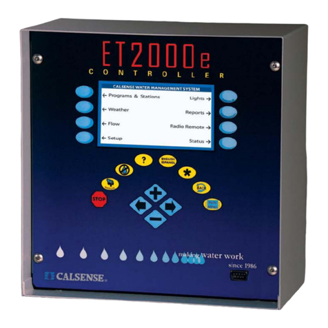
Calsense ET2000 Operating instructions

?
ENGLISH
ESPANOL
MAIN
MENU
BACK
2075 Corte del Nogal, Suite P, Carlsbad CA 92011
1-800-572-8608 FAX:760-438-2619
www.calsense.com
ET2000 PROGRAMMING GUIDE
CONTROLLER STATUS
(adjust stations)
No Stations are Watering
NEXT SCHEDULED IRRIGATION IS AT :
12:00 AM on Saturday Aug 17, 2002
Aug 16 2002
Sat 10:45:03 AM
Stock No. 4039 Rev 09/02

Table of Contents
1. ET2000 Key Pad Description ........................................................................................................................4
2. ET2000 Controller Screen Map .....................................................................................................................5
3. What Can Be Programmed At Each Screen ...................................................................................................6
4. Using This Guide With The ET2000 Controller ...............................................................................................7
5. Start Times & Water Days.............................................................................................................................8
Finish Times ............................................................................................................................................8
6. Station Programming ....................................................................................................................................9
Station Settings .......................................................................................................................................9
Cycle and Soak Examples........................................................................................................................9
Test a Station at the Station Programming Screen .....................................................................................9
Set No Water Days at the Station Programming Screen .............................................................................9
7. Station-to-Station Copy ............................................................................................................................... 10
Making a Station Current ........................................................................................................................ 10
Copy a Station to Another Station............................................................................................................ 10
Copy a Station to All Stations on a Program, or All Stations on the Controller ............................................ 10
8. Flow Meter, Master Valve & Pump Setup ..................................................................................................... 10
Estimated Water Use ............................................................................................................................. 10
Flow Meter Setup................................................................................................................................... 11
Flow Meter Settings ............................................................................................................................... 12
Master Valve ......................................................................................................................................... 14
Pump Output ......................................................................................................................................... 14
9. Manual Key ................................................................................................................................................ 15
Manual Water ........................................................................................................................................ 15
Test....................................................................................................................................................... 15
Master Valve ......................................................................................................................................... 16
Manual Special Sequence ...................................................................................................................... 16
Scheduled Manual Special Sequence ..................................................................................................... 17
10. No Water Key .......................................................................................................................................... 17
Turn a Controller Off .............................................................................................................................. 17
Set No Water Days for a Program or All Stations ..................................................................................... 17
Set No Water Days for Individual Stations ............................................................................................... 18
11. Help Key .................................................................................................................................................. 18
12. English / Spanish Key ............................................................................................................................... 18
13. Stop Key .................................................................................................................................................. 18
14. Setup....................................................................................................................................................... 18
Date & Time .......................................................................................................................................... 18
Stations In Use ...................................................................................................................................... 19
Password .............................................................................................................................................. 19
Communications .................................................................................................................................... 19

Table of Contents
15. Reports .................................................................................................................................................... 20
This Month / Last Month ......................................................................................................................... 20
24 Month History ................................................................................................................................... 20
Irrigation Details..................................................................................................................................... 21
Station Order ......................................................................................................................................... 21
Diagnostics............................................................................................................................................ 21
Log Lines .............................................................................................................................................. 22
ET & Rain Tables ................................................................................................................................... 22
16. Controller Status....................................................................................................................................... 23
Status Screen ........................................................................................................................................ 23
Station Alerts ......................................................................................................................................... 23
17. Weather Setup ......................................................................................................................................... 23
Wind Gage Setup .................................................................................................................................. 24
Rain Switch Setup ................................................................................................................................. 24
Moisture Sensor Setup ........................................................................................................................... 25
18. Lights....................................................................................................................................................... 26
Programming a Lights Schedule ............................................................................................................. 26
Testing a Lights Circuit ........................................................................................................................... 26
19. Radio Remote .......................................................................................................................................... 26

4
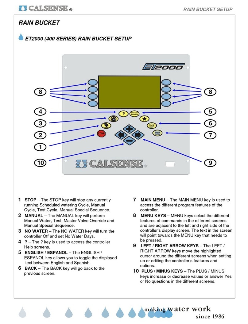
HOT KEYS
HOT keys are action keys. They are used to perform com-
mon controller functions now. The following is a list of HOT
keys and a description of each key function.
STOP
The STOP key will stop any currently running Scheduled
Watering Cycle, Manual Cycle, Test Cycle, Manual Spe-
cial Sequence or Master Valve override.
MANUAL
The MANUAL key will perform Manual Water, Test, Mas-
ter Valve Override and Manual Special Sequence.
NO WATER
The NO WATER key will turn the controller Off and set No
Water Days.
?
The ? key is used to access the controller Help screens.
ENGLISH / ESPANOL
The ENGLISH / ESPANOL key allows you to toggle the
displayed text between English and Spanish.
BACK
The BACK key will go back to the previous screen.
MAIN MENU
The MAIN MENU key is used to access the different pro-
gram features of the controller.
10
1
7
9
8
5
6
4
3
MENU KEYS
MENU keys select the different features or commands in
the different screens and are adjacent to the left and right
side of the controller’s display screen. The text in the screen
will point towards the MENU key that needs to be pressed.
OTHER KEYS
LEFT / RIGHT ARROW KEYS
The LEFT / RIGHT ARROW keys move the highlighted
cursor around the different screens when setting up or ed-
iting the controller’s features and options.
PLUS / MINUS KEYS
The PLUS / MINUS keys increase or decrease values or
answer Yes or No questions in the different screens.
1. ET2000 Key Pad Description
?
ENGLISH
ESPANOL
MAIN
MENU
BACK
1
2
3
45
6
8 8
9
7
10
2

5
2. ET2000 Controller Screen Map
The Screen Map below shows the series of keys to be pressed to access the various screens in the ET2000 Controller. The chart
on the following page explains what can be programmed at each of the screens.
Station Order
Irrigation Details
ET / Rain Table
Log Lines
Diagnostics
Master Valve
Pump Output
Flow Meter
Weather
Flow
Setup
Reports
Radio Remote
(available if option is installed)
Lights
(available if option is installed)
Status
Password
Date & Time
Communications
Stations in Use
This Month / Last Month
24 Month History
ET Gage
Rain Bucket
Wind Gage
ET
Rain Switch
Budget
Moisture
ET County / City
(if in Daily ET mode)
Limit / Learned
Delay Time
Alert Action
Mainline Break
Use of Rain by Program
Moisture Sensing Setup
Crop Coefficents
(if in Daily ET mode)
SensorAssignment
(if in Moisture Sensing mode)
Adjust Learned Numbers
(if in Learned mode)
Adjust Limit Numbers
(if in Limit mode)
Start Times & Water Days
Programs
& Stations Station-to-Station Copy
Stations
Finish Times
Station Programming
(available if flow meter is enabled)
(available if option is installed)
MAIN
MENU
M
A
N
U
A
L
Manual Water
Test
Master Valve
Manual Special Sequence
Manual Irrigation
Valve Testing
Master Valve Override
Set Manual Special Sequence
Turn Controller Off & No Water Days
Station Programming
Station Alerts
(if any)
Controller Alerts
(if any)
Lights Scheduling & Manual Operation
Radio Remote Activation

6
3. What Can Be Programmed At Each Screen
Programs
& Stations Set use of 12 month schedule
Start Times
& Water Days
Set program start time
Select program description
Set number of water days in schedule
Set water days
Set program hold-over time
Set all the above for each month of the year
(optional)
(optional)
If 12 month schedule is enabled :
Finish Times Automatically calculates finish times
for all programs
Station
Programming
If not in Daily ET mode :
If in Daily ET mode :
Set station program assignment
Set total minutes
Set minutes per cycle
Set soak-in time
Set no water days
Test station
Set station program assignment
Set % of ET
Set minutes per cycle
Set soak-in time
Set no water days
Set flow rate (gpm)
Set area (sq. ft.)
Test station
Station-to-Station
Copy Copy one station to any other station
Copy one station to all stations on a program
Copy one station to all stations
ET Gage
Rain Bucket
Use of Rain
by Program
Wind Gage
Rain Switch
ET
Select to use the ET gage
Select to log ET pulses
Reset full gage
Set minimum rain
Set maximum hourly rain
Set maximum 24 hour rain
Set maximum total rain
Set use of rain (by program)
Select to use the wind gage
Set wind speed for pausing irrigation
Set wind speed for resuming irrigation
Select to use a rain switch device
Select to use daily ET (by program)
Select to use ET averaging (by program)
Crop
Coefficients Select to use crop coefficients
Set crop coefficients
Budget Select to use a budget
Select budget option
Calculate budget
View monthly budget totals
Moisture Select to use moisture sensing (by program)
Assign sensor slaving to valves
ET County / City Select county and city for ET
View historical ET totals
Flow Meter
Select to use a flow meter
Select to use list or enter own parameters
Set flow meter size / Set own parameters
Select as master controller
Master Valve Select type of master valve
Pump Output Select pump output type
Select use of pump (by program)
Limit / Learned
Select to use limit mode or learned mode
Set all learned flow rates (if in learned mode)
Set all high & low limits (if in limit mode)
Adjust learned flow rates (if in learned mode)
Adjust high & low limits (if in limit mode)
Delay Time Set delay time
Set trip %
AlertActions Set high flow alert actions
Set low flow alert actions
Mainline Break Set mainline break numbers
Set system maximum flow capability
Password Enter a password (if password has been set)
Date & Time Set the date
Set the time
Select to use daylight savings
Communications Set communications address
Station In Use Select station usage
Lights Set on and off times for lights
Test lights
SCREEN SETTINGS SCREEN SETTINGS
This Month /
Last Month
24 Month History
Irrigation
Details
Station Order
Diagnostics
Log Lines
Use vs Budget
ET & Rain
Tables
Radio Remote
Status
View water usage and irrigation time
View yearly water usage & budget totals
View or clear hold-over time
View or clear ongoing irrigation
View the turn-on order of stations during
scheduled irrigation
View diagnostics
View station log lines
View actual & expected water usage compared
to budget
View or edit ET table
View rain table
Manually enable radio remote
Set normal command code
Set addressed command code
Set receiver frequency
View current status of controller
View next scheduled irrigation
Turn controller on (if it has been turned off)
Manual water a station
Manual water a Program
Manual water all stations
Set cycle and soak
Manual
Irrigation
Valve Testing Set test time
Test a station
Test a Program
Test all stations
No Water Turn controller off
Set no water days
View or edit no water day summary
StationAlerts
Controller Alerts
View and/or clear station alerts
View and/or clear controller alerts
P
R
O
G
R
A
M
S
&
S
T
A
T
I
O
N
S
W
E
A
T
H
E
R
R
E
P
O
R
T
S
F
L
O
W
M
A
N
U
A
L
O
F
F
M
I
S
C
E
L
L
A
N
E
O
U
S
F
L
O
W
S
E
T
U
P
7
4. Using This Guide With The ET2000 Controller
This guide will explain the operation and programming of the ET2000 Controller (for programming the more advanced features of
the ET2000, see our ET Based Water Management guide). The following describes the conventions used throughout this guide.
When instructed to press a key, the name of the key will be CAPITALIZED AND BOLD. The illustration below shows the name and
location of the keys used for operating and programming the ET2000 Controller.
The eight keys located on either side of the controller’s screen are Menu Keys, a Menu Key’s name will be the text on the screen
next to the arrow, this text will change with each screen. The arrow will point to the Menu Key that is to be pressed, the name of the
key will be CAPITALIZED AND BOLD.
There are seven Hot Keys (see Key Pad Descriptions on page 6 ), they are the STOP Key, MANUAL Key, NO WATER Key, HELP
Key, ENGLISH / SPANISH Key, BACK Key and the MAIN MENU Key. The controller screen in the illustration below shows the
Main Menu, which can be accessed at any time by pressing the MAIN MENU Key. The descriptions on the screen with the arrows,
are pointing to the Menu Keys which are to be pressed to access the various parts of the controller’s program (see ET2000 Screen
Map on page 5 ). Most programming functions will begin from the Main Menu. As you navigate through the various screens you
can always return to a previous screen by pressing the BACK key.
The last four keys are the PLUS Key, MINUS Key and the two ARROW Keys. When a screen is accessed that has a setting which
can be changed, there will be a highlighted cursor on the screen, you will use either ARROW Key to move the cursor to the setting
you want to change. A change can only be made to a setting while it is highlighted by the cursor. Once a setting is highlighted, use
the PLUS or MINUS Key to make the change to the setting. If the setting is a number, you can quickly scroll to the desired setting
by pressing and holding down the PLUS or MINUS Key.
CALSENSE WATER MANAGEMENT SYSTEM
Programs & Stations Lights
Weather
Flow
Setup
Reports
Radio Remote
Status
Menu
Keys
Menu
Keys
Back Key
Main Menu Key
Controller Screen Showing Main Menu
Arrow Keys
Plus and Minus Keys
?
ENGLISH
ESPANOL
M
A
N
U
A
L
English / Spanish Key
Help Key
No Water Key
Manual Key
Stop Key
Menu Key Name

8
5. Start Times & Water Days
From the Main Menu Press the PROGRAMS & STATIONS Menu Key, then Press the START TIMES & WATER DAYS Menu
Key, the Start Times & Water Days screen will appear (shown below).
Press either ARROW Key to move the cursor to the setting you wish to change, Press the PLUS or MINUS Key to change the
highlighted setting. When at the Start Times & Water Days screen the two top right Menu Keys have a special function, they are
used to scroll to the different programs. The following explains each setting on the Start Times & Water Days screen.
PROG: Indicates the current program. Program B is being programmed in the example above. The ET2000 Control-
ler has 7 programs, A, B, C, D, E, Drip 1, and Drip 2. Programs A, B, C, D,& E have overlap protection, no
station is able to irrigate at the same time as another station. Programs Drip 1 and Drip 2 are designed to be
able to irrigate simultaneously with other stations, in this way the user can irrigate up 3 stations at the same
time by entering identical start times on Programs Drip 1, Drip 2 and any one of the remaining 5 Programs.
Start Time: The start time for scheduled irrigation on the current program. Program B has a 11:30 PM Start Time in the
example above.
Name: A program description can be selected which describes the type of plant material and irrigation heads as-
signed to that program (this setting is optional).
Days in Schedule: The ET2000 can be set with a 7-Day Schedule (shown in the example above), 14-Day Schedule, 21-Day
Schedule or 28-Day Schedule.
Water Days: The days of the week in the schedule to irrigate. “on” represents a water day, “--” represents an off day.
Hold-Over Time: A time at which irrigation is forced to end, even if the scheduled irrigation cycle is not finished. This setting is
to be used only if the controller is in Daily-ET mode (see the ET Based Water Management Guide for more
information).
Finish Times: Calculates the end-time of each programs scheduled irrigation cycle.
Finish Times
Press the FINISH TIMES Menu Key, the Finish Times screen will appear (shown below). In the example below, the finish times
for Programs A, B and DRIP 1 have been calculated. The NO RUN on Programs C, D, E and DRIP 2 indicates those programs
are not being used. If ERROR was shown next to a program, it would indicate that the program has a run-time longer that 24
hours, and must be reprogrammed to correct the error.
RESULTS OF FINISH TIMES CALCULATION
ET-TABLEHISTORICAL% OF ET
PROG A:7:20 AM
PROG B:3:15 AM
PROG C:NO RUN
PROG D:NO RUN
PROG E:NO RUN
DRIP 1:2:30 AM
DRIP 2:NO RUN
Note : The Historical and % of ET columns are used for information only if the controller is in Daily-ET mode.
START TIMES & WATER DAYS
Program :PROG BStart Time : 11:30PM
Name :. . . . . . . . . . . . . . . .
Number of Days in Schedule : 07
SunMonTueWedThuFriSAT
WEEK 1on--on--onon
Hold-Over Time : OFFFinish Times
(by program)
on
S
T
A
T
I
O
N
U
P
These Menu Keys are
used to scroll to any
of the seven programs

9
6. Station Programming
Station Settings
From the Main Menu Press the PROGRAMS & STATIONS Menu Key, then Press the STATIONS Menu Key, the Station
Programming screen will appear (shown below).
Press either ARROW Key to move the cursor to the setting you wish to change, Press the PLUS or MINUS Key to change the
highlighted setting. When at the Station Programming screen, the two top right Menu Keys have a special function, they are
used as the STATION UP and STATION DOWN Keys. The following explains each setting on the Start Times & Water Days
screen.
Station: Indicates the current station number (station 1 in the example above).
PROG: Indicates the program that the current station is assigned to (program A in the example above). A station can
be assigned to only one program at one time.
Total Mins: The total amount of irrigation time that will be applied in each 24 hour watering period.
Mins Per Cycle: The amount of irrigation time applied in each cycle of a 24 hour watering period.
Soak-in Time: The amount of time (in minutes) between multiple cycle starts (if there are multiple cycle starts). If there are
no multiple cycle starts, this setting will be ignored by the program.
Cycle and Soak Examples
In the example shown above, station 1 will irrigate for 5 minutes (the Mins per Cycle setting) then wait 60 minutes (the Soak-In
Time setting), it will repeat the process two more times until the total irrigation applied is 15 minutes (the Total Mins setting), this
feature is called Cycle and Soak. Each station’s Cycle and Soak settings can be set independent of any other station’s settings.
The following shows some examples of Cycle and Soak settings:
S
T
A
T
I
O
N
U
P
STATION PROGRAMMING
Station 1 . . . . . . . . . . . . . . . . . . PROG A
Total Mins:
Mins per Cycle:5
Soak-In Time:60No Water Day 0
Test
15.0
Station Up Key
Station Down Key
Total Mins : 10.0
Mins per Cycle : 10
Soak-In Time : 5
Total Mins : 20.0
Mins per Cycle : 10
Soak-In Time : 180
Total Mins : 10.0
Mins per Cycle : 2
Soak-In Time : 15
In this example the station would have one 10 minute run time. If the Mins per Cycle is equal
to the Total Mins there will be one run time equal to the Total Mins and the Soak-In Time is
ignored.
In the example the station will have two 10 minute run times with 180 minutes (or 3 hours)
between each run time.
In this example the station will have five 2 minute run times, with 15 minutes between each
run time.
Test a Station at the Station Programming Screen
Press the TEST Menu Key to turn the current station on. The run time will be whatever has been set at the Valve Testing screen
(see pages 15 & 16 for more information about Testing Valves). Press the STOP Key to end the test before the end of the test
run time is reached.
Set No Water Days at the Station Programming Screen
To turn the current station off for 1 to 31 days, Press the ARROW Key to highlight the No Water Day setting. Press the PLUS or
MINUS Key to set the number of No Water Days desired (see pages 17 & 18 for more information about No Water Days).

10
7. Station-to-Station Copy
From the Main Menu Press the PROGRAMS & STATIONS Menu Key, then the STATION-TO-STATION COPY Menu Key. The
Station To Station Copy Screen will appear (shown below). From the Station To Station Copy screen you can copy the programming
from one station to another station, copy the programming from one station to all stations on any program, or copy the programming
from one station to all stations on the controller. The settings that are copied are the Total Mins setting (except in Daily-ET mode),
the Mins Per Cycle setting and the Soak-In Time setting.
STATION TO STATION COPY
Items copied from Station to Station :
Total Mins*
Mins Per Cycle
Soak-In Time
*except to Daily ET stations
Copy from Station 4 to Station 2
Copy Station 4 to PROG A Stations
Making a Station Current
The station you want to copy from, must be made the current station before it can be copied. To make a station current, Press
the MAIN MENU Key, Press the PROGRAMS & STATIONS Menu Key, then the STATIONS Menu Key. Press STATION UP or
STATION DOWN until you reach the station you wish to copy from. In the example above, station 4 was made the current station
before the Station To Station Copy screen was accessed.
Copy a Station to Another Station
At the Station To Station Copy screen Press the PLUS or MINUS Key until the station is selected (station 2 was selected in the
example above), Press the COPY FROM STATION TO STATION Menu Key, the station will be copied and you will be returned
to the Programs & Stations screen. If you wish to copy the current station to another station, Press the STATION-TO-STATION
COPY Menu Key to return to the Station To Station Copy screen and repeat the copy process described above.
Copy a Station to All Stations on a Program, or All Stations on the Controller
At the Station To Station Copy screen Press an ARROW Key to move the cursor, Press the PLUS or MINUS Key to select all
stations or a program, Press the COPY STATION TO PROG Menu Key, the station will copied and you will be returned to the
Programs & Stations screen.
8. Flow Meter, Master Valve & Pump Setup
From the Main Menu Press the FLOW Menu Key, the Flow Meter, Master Valve & Pump Setup screen will appear (shown below).
Flow Meter
Master Valve
Pump Output
FLOW METER, MASTER VALVE & PUMP SETUP
Do You want to track
Estimated Water Use? NO
Estimated Water Use
The Estimated Water Use setting is set to YES only if there is no flow meter installed. If there is no flow meter installed, and you
want to track estimated water usage, change the setting to YES, return to the Station Programming screen (see page 9) and set
the flow rate for each station (the flow rate setting appears on the Station Programming screen only when the Estimated Water
Use setting is set to YES).

11
Flow Meter Setup
From the Flow Meter, Master Valve & Pump Setup screen, Press the FLOW METER Menu Key, the Flow Meter screen will appear
(it will appear as shown below only after the Flow Meter In Use setting is set to YES). Press the ARROW Key to move the cursor
to the desired setting, the three settings are described below.
FLOW METER
Flow Meter is in use ?
Choose the Flow Meter from a list OR
set your own Parameters ?CHOOSE FROM LIST
Meter 1
CHOICE:NOT USED
Is this a MASTER CONTROLLER ? NO
YES
1. The first setting is the type of flow meter installed on the system. If the flow meter is a standard Calsense Flow Meter, leave the
setting at CHOOSE FROM LIST (the default setting). If the flow meter is a Calsense FMBX, change the setting to ENTER OWN
PARAMETERS (described later on this page).
2. The next setting is the model of flow meter installed (the default setting is NOT USED). The list of choices are:
FM-1 1” plastic flow meter
FM-1B 1” brass flow meter
FM-1.25B 1 1/4” brass flow meter
FM-1.5 1 1/2” plastic flow meter
FM-2 2” plastic or brass flow meter
FM-3 3” plastic flow meter
NOTE : Most Calsense Controllers are connected to only one flow meter, which is why the choice of flow meter model heading
in the example screens show only Meter 1. If the controller has the -F option installed (use of multiple flow meters), there will be
three headings, Meter 1, Meter 2 and Meter 3, and a choice of model for each flow meter installed.
3. The MASTER CONTROLLER setting will appear with NO selected (as shown above). In most cases this setting will not change.
If a system has multiple controllers on a single mainline, and more than one controller has to irrigate at the same time, one controller
is designated as the master controller (and is connected to a Calsense flow meter). All other controllers have flow monitoring
disabled. The job of the master controller is to continuously monitor for mainline breaks, no other flow monitoring features will be
enabled for the master controller.
If the flow meter installed on the system is a Calsense FMBX change the Choose Flow Meter setting to ENTER OWN
PARAMETERS (the screen will appear as shown below).
FLOW METER
Flow Meter is in use ?
Choose the Flow Meter from a list OR
set your own Parameters ?
ENTER OWN PARAMETERS
Meter 1
K:10.000
OFFSET:0.200
Is this a MASTER CONTROLLER ? NO
YES
The two settings that must be set are the K value and the OFFSET value. Follow the instructions that are shipped with the Calsense
FMBX Flow Meter, or call Calsense at 800-572-8608 for assistance.

12
Limit / Learned Flow Meter
Delay Time
Alert Actions
Mainline Break
Master Valve
Pump Output
FLOW METER, MASTER VALVE & PUMP SETUP
Flow Meter Settings
After the flow meter has been enabled at the Flow Meter screen as described on the previous page, Press the BACK Key to
return to the Flow Meter, Master Valve & Pump Setup screen (shown below), it will appear with four new Menu Key choices.
These are the flow meter settings, and are available only after a flow meter has been enabled (note that the Estimated Water Use
setting is no longer available as described on page 10).
Press the LIMIT / LEARNED Menu Key, the Learned or Limit screen will appear (as shown below). Using learned mode is
recommended (the default setting).
Push HERE to set all LEARNED values
Adjust Learned Numbers Here
LEARNED OR LIMIT
to 700 gpm
LEARNED (recommended) or LIMIT for your
mode of Over-Flow / Low-Flow detection ?
Use LEARNED mode
In learned mode the controller will learn the flow rate of each station (approximatley 6 to 10 scheduled irrigation cycles are required
to learn a station’s flow rate). The controller will then use this learned flow rate to alert the user when HIGH FLOWS and NO
FLOWS occur.
Press the ARROW Key to move the cursor to the SET ALL LEARNED VALUES Menu Key, use the PLUS or MINUS Key to set
the desired gpm, then Press SET ALL LEARNED VALUES the Menu Key to set the value. This setting is used to set or re-set all
stations initial learned flow rates, it must be a value higher than any station’s flow rate, if you do not know the station flow rates,
leave the number at 700 gpm.
Press the ARROW Key to move the cursor to the ADJUST LEARNED NUMBERS Menu Key, Press the Menu Key to access
the Learned GPM for Each Valve screen (shown below). At this screen you can view and adjust individual station learned flow
rates.
LEARNED GPM FOR EACH VALVE
12345678910
4562182233285210225
11121314151617181920
46785228324183700700700
21222324
700700700700
36
Press the ARROW Key to move the cursor to the flow rate under the station that is to be adjusted, Press the PLUS or MINUS
Key to adjust the station’s flow rate.

13
Flow Meter Settings (con’t)
From the Flow Meter, Master Valve & Pump Setup screen, Press the DELAY TIME Menu Key to access the Delay Time & Trip
Percent screen (shown below).
DELAY TIME & TRIP PERCENT
Delay Time is in seconds
DelayTrip
Time%
PROG A . . . . . . . . . . . . .15%120
PROG B . . . . . . . . . . . . .12015%
PROG C . . . . . . . . . . . . .12015%
PROG D . . . . . . . . . . . . .12015%
PROG E . . . . . . . . . . . . .12015%
DRIP 1 . . . . . . . . . . . . .12015%
DRIP 2 . . . . . . . . . . . . .12015%
The default settings for each program are a 120 second delay time and a 15% trip percentage set. Press an ARROW Key to
move the cursor to the desired setting, Press the PLUS or MINUS Key to change the setting. Each program can be independently
set with a delay time of 15 to 1,800 seconds and a trip percentage of 1 to 99 percent.
The Delay Time is the amount of time the controller waits after activating a valve before taking a flow reading. This allows for an
accurate flow reading, by giving time for air to be flushed from piping and the previous valve to shut down. The only restriction is
that the flow delay time should not be longer than a station’s run time.
The Trip Percent is the amount of increase above the learned flow rate at which the controller will alert the user to a HIGH FLOW.
From the Flow Meter, Master Valve & Pump Setup screen, Press the ALERT ACTIONS Menu Key to access the Alert Actions
screen (shown below).
ALERT ACTIONS
HIGH FLOWLOW FLOW
PROGA:Alert / No ActionAlert / No Action
PROGB:Alert / No ActionAlert / No Action
PROGC:Alert / No ActionAlert / No Action
PROGD:Alert / No ActionAlert / No Action
PROGE:Alert / No ActionAlert / No Action
DRIP1:Alert / No ActionAlert / No Action
DRIP2:Alert / No ActionAlert / No Action
MAINLINE BREAK & MAX FLOW NUMBERS
Mainline Break Numbers :
DURING IRRIGATION is gpm
AT ALL OTHER TIMES is 700 gpm
System Max Flow Capability is 999 gpm
700
The Alert Actions setting defaults with Alert / No Action set for all programs. There are three possible settings :
1. Alert / No Action : An alert is displayed on the screen but the valve continues to irrigate.
2. Alert / Shut-Off : An alert is displayed on the screen and the valve is shut down.
3. No Alerts : No alert is displayed and the valve continues to irrigate.
From the Flow Meter, Master Valve & Pump Setup screen, Press the MAINLINE BREAK Menu Key to access the Mainline Break
& Max Flow Numbers screen (shown below).
The default mainline break number will be set at 700 gpm. The During Irrigation number is the mainline break number used while
the controller is irrigating, the All Other Times number is the mainline break number used when the controller is not irrigating. A
typical mainline break setting might be slightly more than twice the flow rate of the highest flowing valve on the system.
The Max Flow Capability setting is the maximum flow capacity of the system’s water meter. If multiple valves are irrigating at the
same time and this flow rate is exceeded, the controller will turn off a valve(s) until the flow rate is below the maximum capability
setting. It will turn the valve back on and continue irrigating at a later time.

14
Master Valve
From the Flow Meter, Master Valve & Pump Setup screen, Press the MASTER VALVE Menu Key, the Type of Master Valve
screen will appear (shown below).
TYPE OF MASTER VALVE
The MASTER VALVE is NORMALLY CLOSED
PUMP OUTPUT OPTIONS
Pump Output Used as
Pump Output Enabled for :
PROGA . . . . . . . . . . . . . . . . .YES
NORMAL PUMP OUTPUT
PROGB . . . . . . . . . . . . . . . . .YES
PROGC . . . . . . . . . . . . . . . . .YES
PROGD . . . . . . . . . . . . . . . . .YES
PROGE . . . . . . . . . . . . . . . . .YES
DRIP1 . . . . . . . . . . . . . . . . .YES
DRIP2 . . . . . . . . . . . . . . . . .YES
The Master Valve default setting is for a normally closed master valve. There are 2 settings, NORMALLY CLOSED, if a normally
closed master valve is installed and NORMALLY OPEN, if a normally open master valve is installed. Be sure to select the correct
type of master valve installed, if it is incorrect the master valve will be closed whenever a station is irrigated and no water will flow.
Pump Output
From the Flow Meter, Master Valve & Pump Setup screen, Press the PUMP OUTPUT Menu Key, the Pump Output Options
screen will appear (shown below).
The Pump Output Used will be highlighted and the default setting will be set for NORMAL PUMP OUTPUT, to change the setting
Press the PLUS or MINUS Key. There are three settings. NORMAL PUMP OUTPUT, if a pump is installed or if a pump is not
installed and the output is not used for a special purpose. STEADY ALERT LIGHT or BLINKING ALERT LIGHT, if the pump
output is to be connected to some type of signaling device such as a light to alert the user to a possible problem (e.g. MAINLINE
BREAK alert )
Press an ARROW Key to move the cursor to the Pump Output Enabled setting, the default setting is set to YES on all programs,
this means that the controller’s pump output will be activated whenever a station on any program is activated. To change the
setting Press the PLUS or MINUS Key for any program to set the Pump Output Enabled setting to NO. If the Pump Output
Enabled setting is set to NO on a program, the pump output will not activate when a station on that program is activated.

15
9. Manual Key
Press the MANUAL Key to access the Manual Irrigation screen (shown below). From this screen you can choose to manually
irrigate stations , test stations, override the master valve and set a manual special sequence.
M
A
N
U
A
L
Manual Water
Test
Master Valve
Manual Special Sequence
MANUAL IRRIGATION
Manual Water
Press the MANUAL WATER Menu Key to access the Manual Irrigation screen (shown below).
Manual Water Station for 10.0 mins1
Manual Water PROG A Stations
MANUAL IRRIGATION
Cycle & Soak During Manual ? NO
Test Station 5
Test PROG B Stations
VALVE TESTING
Test will Run for 2.0 Minutes
The Manual Water Station xx will be highlighted ,Press the PLUS or MINUS Key to select the desired station (station 1 has been
selected in the example above). Press the MANUAL WATER STATION xx Menu Key to manually water the selected station.
The manual run time will be the scheduled run time for that station (the run time is 10 minutes in the example above). To end the
manual cycle before the run time, Press the STOP Key
To water all stations on a program or all stations on the controller, Press the ARROW Key to move the cursor to the Manual
Water xxxx Stations setting, Press the PLUS or MINUS to select the desired Program or ALL stations (PROG A has been selected
in the example above), then Press the MANUAL WATER xxxx STATIONS Menu Key to start manually watering the selected
program or all stations on the controller. To end the manual cycle before all of the stations have run, Press the STOP Key.
The last setting at the Manual Irrigation screen is the Cycle and Soak During Manual setting, it’s default setting is NO. If the
selection is set to NO, the run time during manual operation will be the Total Mins setting (set at the Station Programming screen,
see page 9). If the selection is set to YES, the controller will use the Total Mins, Mins Per Cycle and the Soak in Time settings (set
at the Station Programming screen, see page 9) during manual operation.
Test
From the Manual Irrigation screen, Press the TEST Menu Key, the Valve Testing screen will appear (shown below).
The Test Station xx setting will be highlighted, Press the PLUS or MINUS Key to select the desired station (station 5 has been
selected in example above). To change the Test Run Time before starting the test, Press an ARROW Key to move the cursor to
the Test Run Time setting, Press the PLUS or MINUS Key to set the amount of time, Press the TEST STATION xx Menu Key to
start the station test. To end the station test before the test cycle is complete, Press the STOP Key.

16
Test (con’t)
To run a test cycle of all the stations on a program or all the stations on the controller, Press an ARROW Key to move the cursor
to the Test xxxx Stations setting. Press the PLUS or MINUS Key to select the desired Program or ALL stations (PROG B has
been selected in the example on the previous page), Press the TEST xxxx STATIONS Menu Key to start the test cycle. To end
the test cycle before all of the stations have completed the test, Press the STOP Key.
Master Valve
From the Manual Irrigation screen, Press the MASTER VALVE Menu Key, the Master Valve Override screen will appear (shown
below). At this screen the master valve can be opened or closed, depending on the type of master valve installed on the system,
for a selected amount of time between 1 hour and 24 hours. At the end of the selected time, the master valve override will end.
MASTER VALVE OVERRIDE
OPEN the MASTER VALVE for 8 HOURS
MANUAL SEQUENCE STATIONS & TIMES
Stations:14--------------
Minutes:510----------------
--
Stations:--------------------
Minutes:--------------------
Stations:--------------------
Minutes:--------------------
Stations:--------------------
Minutes:--------------------
(use BACK key when done)
MANUAL SPECIAL SEQUENCE
Start Times :OFF
Number of Cycles :1
Schedule :---------------------
Run Until :Aug 15 2002, Thu
NOW
Set the STATIONS & TIMES
PRESS HERE TO RUN IT
( Detected a NOW start time )
Press the PLUS or MINUS Key to select the OPEN or CLOSE setting. Press an ARROW Key to move the cursor to the HOURS
setting, Press the PLUS or MINUS Key to set the desired number of hours of override. Press the xxxx MASTER VALVE FOR x
Menu Key to start the master valve override. To end the override before the set end time, Press the STOP Key.
Note : Scheduled irrigation will not occur while the master valve override is activated.
Manual Special Sequence
From the Manual Irrigation screen, Press the MANUAL SPECIAL SEQUENCE Menu Key, the Manual Special Sequence screen
will appear (shown below). If the Manual Special Sequence has never been programmed it will appear with the default settings
shown below (the date will be the current date).
To manually start a sequence the Start Time setting will be set to NOW (as shown in the example above), Press the SET STATIONS
& TIMES Menu Key, the Manual Sequence Stations & Times screen will appear (shown below).
Using the PLUS or MINUS Key and the ARROWKeys, set the desired stations and run times for manual operation. In the example
above station 1 has been set with a run time of 5 minutes and station 4 has been set with a run time of 10 minutes. After all
stations have been set, Press the BACK Key to return to the Manual Special Sequence screen, then Press the PRESS TO RUN
IT Menu Key to start the manual sequence. To end the manual sequence before all stations have finished, Press the STOP Key.

17
MANUAL SPECIAL SEQUENCE
Start Times :OFF
Number of Cycles :2
Between Cycle Starts:120
Schedule :---Mon---Wed---Fri---
Run Until :Aug 15 2003, Thu
2:00AM
Set the STATIONS & TIMES
Scheduled Manual Special Sequence
To set a scheduled manual special sequence, Press an ARROW Key to move the cursor to the first Start Times setting, Press
the PLUS or MINUS Key to set a start time (2:00AM has been set in the example below), a second start time can be set if
desired. Press an ARROW Key to move the cursor to the Number of Cycles setting, this setting determines how many times to
run the sequence each day, use the PLUS or MINUS Key to change the setting. Press an ARROW Key to move the cursor to
the Between Cycle Starts setting, this determines the amount of time (in minutes) between each cycle start, use the PLUS or
MINUS Key to change the setting. Press an ARROW Key to move the cursor to the Schedule setting, use the PLUS Key to turn
a water day on (Mon, Wed and Fri are scheduled water days in the example below) and the MINUS Key to turn a day off. Press
an ARROW Key to move the cursor to the Run Until setting, this setting determines when the manual special sequence will end
(Aug 15, 2003 in the example below), Press the PLUS Key to set the date. Press the SET STATIONS & TIMES Menu Key to set
which stations to manually irrigate and set the run times of each of those stations (described on the previous page).
If scheduled irrigation is running when the manual special sequence is set to start, it will be temporarily halted until the manual
special sequence is finished, then resume where it left off.
TURN CONTROLLER OFF & NO WATER
Turn Controller OFF
Apply No Water Day(s) to : PROG A3
No Water Days Summary
( no water by station )
Turn a Controller Off
Press the TURN CONTROLLER OFF Menu Key. The controller will be turned off and will immediately return to the STATUS
screen. To turn the controller back on, Press the PUSH TO TURN ON Menu Key located at the STATUS screen.
Set No Water Days for a Program or All Stations
Press the ARROW Key to move the highlight to the number of No Water Days setting. Press the PLUS or MINUS Key to set the
desired number of No Water Days. Press the ARROW Key to highlight which program to set the No Water Days for. Press the
PLUS or MINUS Key to select the desired program (or all stations). Press the APPLY NO WATER DAYS Menu Key. In the
example above, all stations on Program B will be turned off for 3 days. To turn Program B back on at anytime, return to the
TURN CONTROLLER OFF & NO WATER screen and set the No Water Days to 0, and Press the APPLY NO WATER DAYS
Menu Key.
10. No Water Key
Press the NO WATER Key to access the Turn Controller Off & No Water screen (shown below), from this screen you can turn
the controller Off, set No Water Days for indivdual stations, set No Water Days for all stations on the controller, or set No Water
Days for all stations on any of the controller’s seven programs. At the end of the No Water Days setting, the station(s) will start to
irrigate according to their irrigation schedule. The No Water setting can be set from 1 to 31 days.

18
NO WATER DAYS SUMMARY
Station:12345678910
NOW Days:060000000
Station:11121314151617181920
NOW Days:0000000000
Station:21222324252627282930
NOW Days:0000000000
Station:31323334353637383940
NOW Days:0000000000
3
Press the ARROW Key to move the highlight to the desired station, Press the PLUS or MINUS key to set the number of No
Water Days for the station. Repeat for any other stations to be set for No Water Days. In the example above station 2 has been
turned off for 6 days and station 5 has been turned off for 3 days. To turn a station back on at anytime, return to the NO WATER
DAYS SUMMARY screen and set the No Water Days to 0.
11. Help Key
Press the HELP Key to access one of the many ET2000 help screens. The help screen that appears will depend upon which
screen you are viewing when you Press the HELP Key. For example, if you are viewing the Date & Time screen, and you Press
the Help Key, you will access an explanation of how to set the date and time.
The help screen that appears will sometimes not only depend upon which screen you are viewing when you Press the Help Key,
but also where the cursor is on the screen you are viewing. For example, if you are at the Station Programming screen and the
cursor is highlighting the Total Mins setting, and you Press the HELP Key, you will access an explanation of the Total Mins setting.
After viewing a Help screen, Press the BACK Key to return to the screen you were at when you Pressed the Help Key.
12. English / Spanish Key
Press the ENGLISH / ESPANOL Key to toggle between displaying text in English or in Spanish. When in Spanish mode all Help
screens will also be in Spanish.
13. Stop Key
Press the STOP Key to halt any on-going irrigation. The Stop Key will halt scheduled irrigation, manual irrigation and valve testing.
14. Setup
Date & Time
From the Main Menu, Press the SETUP Menu Key, the General Setup screen will appear, Press the DATE & TIME Menu Key,
the Date & Time screen will appear (shown below).
Set No Water Days for Individual Stations
Press the NO WATER DAYS SUMMARY Menu Key to access the NO WATER DAYS SUMMARY screen (shown below).
?
ENGLISH
ESPANOL
Push here to SET IT
DATE & TIME
Current Date & Time :
Aug 19 2002, Mon 4:29:48AM
Date & Time to Set :
19 2002, Mon 4:29:48AMAug
Use Day Light Savings ? YES
Press an ARROW Key to move the cursor to the date & time setting to be changed (month, day, year, hour, minute, seconds),
Press the PLUS or MINUS Key to make the change, Press the PUSH HERE TO SET Menu Key. IMPORTANT : The changes
do not take effect until the PUSH HERE TO SET Menu Key is pressed. If you wish to have the controller automatically change
time for Daylight Savings, make sure the Use Day Light Savings setting is set to YES (the default setting).

19
STATIONS IN USE
12345678910
11121314151617181920
21222324252627------
32--
Stations In Use
From the Main Menu Press the SETUP Menu Key, the General Setup screen will appear, Press the STATIONS IN USE Menu
Key, the Stations In Use screen will appear (shown below). At this screen you can turn-off stations not in use, after a station is
turned-off it will no longer be visible for programming at any other screen.
To turn-off a station, Press an ARROW Key to move the cursor to the desired station, Press the PLUS or MINUS Key to turn-off
the station, two dashed lines will appear instead of the station number. In the example above, stations 28 thur 31 have been
turned-off. To turn a station back on Press an ARROW Key to highlight the station then Press the PLUS of MINUS Key, the
station number will re-appear.
Password
From the Main Menu Press the SETUP Menu Key, the General Setup screen will appear, Press the PASSWORD Menu Key, the
Log In screen will appear (shown below). Using the Calsense Command Center program, a three character password can be
sent to the controller, once a password has been sent, the controller cannot be programmed until the proper password has been
entered at the Log In screen.
Enter Your Login : 0 00
LOG IN
LOG IN
COMMUNICATIONS
COMMUNICATION ADDRESS : ! !
406.p(norm) A=9600 B=9600
2000 BOARD
ET2000-32-LR-G-RR
Copyright Calsense Inc. 1987-2001
All Rights Reserved
!
Enter the first character of the password by Pressing the PLUS or MINUS Key until the character appears, Press the ARROW
Key to move the cursor to the next character, repeat the process described above until all three password characters appear,
then Press the LOG IN Menu Key, a message will appear confirming that the log in was successful.
Communications
From the Main Menu Press the SETUP Menu Key, the General Setup screen will appear, Press the COMMUNICATIONS Menu
Key, the Communications screen will appear (shown below). This screen has a dual purpose:
1. It display’s information about the controller. This information includes ROM version, baud rate, board model, type of controller
and any installed options.
2. If the controller has communications capabilities a three character communications address is set at this screen.
Press the PLUS or MINUS Key to set the first character, Press the ARROW Key to move the cursor to the next character, repeat
the process described above until all three characters are set, nothing more needs to be done.

20
15. Reports
The Calsense ET2000 Controller is capable of storing and displaying a large quantity information pertaining to the operation of
the controller. This information can be accessed from the Main Menu by Pressing the REPORTS Menu Key, the Reports screen
will appear (shown below).
This Month / Last Month
Diagnostics
24 Month History
Irrigation Details
Station Order
Log Lines
ET & Rain Tables
REPORTS
From the Reports screen you can access any of the stored information contained in the ET2000 Controller by Pressing any of
the available Menu Keys (shown above). The following describes the information you can view at each of the report screens.
This Month / Last Month
HCF
Show Time
THIS MONTH / LAST MONTH TOTALS
(gallons)This MonthLast Month
Irrigated:23890.4135291.8
Test & Manual:825.81285.3
Non Controller:1382.21883.3
(total:26098.4138460.4)
STATION
Irrigated:138.21898.0
8
This Month / Last Month (shown above) is a report of water usage. The report can be viewed in gallons, HCF (hundreds of cubic
feet), or minutes by Pressing either the HCF Menu Key, the GALLONS Menu Key or the SHOW TIME Menu Key, the current
view is shown in the upper left corner of the screen (gallons in the example above). The upper part of the screen shows controller
usage totals, the lower part of the screen shows individual station usage totals, Press the STATION UP or STATION DOWN
Menu Keys to view the desired station (station 8 is shown in the example above). The totals are listed in two columns, The Month
column is the total water usage since the 1st day of the current month. The Last Month column is the total water usage for the
entire previous month.
24 Month History
Prior YearUSEBUDGETET
Jan2001000.00
Feb2001000.00
Mar2001000.00
Apr200126380253093.62
May200132283312884.83
Jun200148282492235.32
Jul200153929512836.01
Aug200164833641006.98
Sep200153222503925.51
Oct200141892402994.32
Nov200131223324383.11
Dec200122983213432.01
24 MONTH HISTORY
The 24 Month History (shown above) is another report of water usage. The report can show either the current 12 month period,
or the previous 12 month period by Pressing the PRIOR YEAR Menu Key or the THIS YEAR Menu Key (the Menu Key shown
will depend upon which screen is currently being viewed). The report is listed in three columns:
USE : The amount of water used (gallons)
BUDGET : The amount set in the budget (gallons)
ET : The amount of ET for the month (inches)
Other manuals for ET2000
2
Table of contents
Other Calsense Controllers manuals

Calsense
Calsense ET1 User manual

Calsense
Calsense 500 Series User manual

Calsense
Calsense ET1 User manual

Calsense
Calsense ET2000e User manual

Calsense
Calsense ET2000 500 Series User manual

Calsense
Calsense ET2000 400 Series User manual

Calsense
Calsense ET2000e User manual

Calsense
Calsense CS3000 User manual

Calsense
Calsense ET2000e Operating instructions

Calsense
Calsense 500 Series Operating instructions