FA01467M4A - 10/2021
K
L
M
N
ITALIANO
Avvertenze generali per
l'installatore
Leggere attentamente le istruzioni prima
di iniziare l’installazione ed eseguire gli
interventi come specificato dal costruttore. •
Il prodotto deve essere destinato solo all’uso
per il quale è stato espressamente studiato
e ogni altro uso è da considerarsi pericoloso.
• Il produttore non può essere considerato
responsabile per eventuali danni causati da
usi impropri, erronei ed irragionevoli.
Dismissione e smaltimento
Non disperdere nell’ambiente l’imballaggio
e il dispositivo alla fine del ciclo di vita, ma
smaltirli seguendo le norme vigenti nel paese
di utilizzo del prodotto. I componenti riciclabili
riportano simbolo e sigla del materiale.
I DATI E LE INFORMAZIONI INDICATE IN
QUESTO MANUALE SONO DA RITENERSI
SUSCETTIBILI DI MODIFICA IN QUALSIASI
MOMENTO E SENZA OBBLIGO DI PREAVVISO.
LE MISURE, SE NON DIVERSAMENTE
INDICATO, SONO IN MILLIMETRI.
Descrizione
Appoggio fisso.
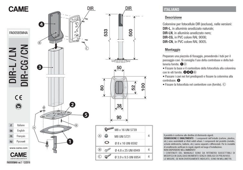
Descrizione delle parti A
1Colonnina
2Staffe di appoggio per asta
3Piastra di fissaggio per staffe di appoggio
4Base colonnina
5Piastra di ancoraggio
6Viti autofilettanti 6,3x19
7Dadi ciechi
8Rondelle
9Viti autofilettanti 6,3x25
10 Viti a testa esagonale M8x16
Dimensioni B
(*) la quota è indicata nel manuale di
installazione della barriera interessata.
ENGLISH
General precautions for installers
Read the instructions carefully before
beginning the installation and carry out the
procedures as specified by the manufacturer.
• Only use this product for its intended
purpose. Any other use is hazardous. • The
manufacturer cannot be held liable for any
damage caused by improper, unreasonable or
erroneous use.
Dismantling and disposal
Dispose of the packaging and the device
responsibly at the end of its life cycle, in
compliance with the laws in force in the
country where the product is used. The
recyclable components are marked with a
symbol and the material ID marker.
THE DATA AND INFORMATION IN THIS
MANUAL MAY BE CHANGED AT ANY TIME
AND WITHOUT NOTICE.
THE MEASUREMENTS, UNLESS OTHERWISE
STATED, ARE IN MILLIMETRES.
Description
Fixed support.
Description of parts A
1Post
2Boom support brackets
3Anchoring plate for support brackets
4Post base
5Anchoring plate
6Self-threading screws 6.3x19
7Cap nuts
8Washers
9Self-threading screws 6.3x25
10 Hex-head screws M8x16
Size B
(*) The measurement is specified in the
installation manual for the relevant barrier.
FRANÇAIS
Instructions générales pour
l’installateur
Lire attentivement les instructions avant de
commencer l'installation et d'effectuer les
interventions comme indiqué par le fabricant.
• Ce produit ne devra être destiné qu'à
l'utilisation pour laquelle il a été expressément
conçu et toute autre utilisation est à considérer
comme dangereuse. • Le fabricant décline
toute responsabilité en cas d’éventuels
dommages provoqués par des utilisations
impropres, incorrectes et déraisonnables.
Mise au rebut et élimination
Ne pas jeter l'emballage et le dispositif dans
la nature au terme du cycle de vie de ce
dernier, mais les éliminer selon les normes en
vigueur dans le pays où le produit est utilisé.
Le symbole et le sigle du matériau figurent sur
les composants recyclables.
LE CONTENU DE CE MANUEL EST
SUSCEPTIBLE DE SUBIR DES MODIFICATIONS
À TOUT MOMENT ET SANS AUCUN PRÉAVIS.
LES DIMENSIONS SONT EXPRIMÉES EN
MILLIMÈTRES, SAUF INDICATION CONTRAIRE.
Description
Support fixe.
Description des parties A
1Colonne
2Support de fixation pour lisse
3Plaque de fixation pour étriers de fixation
4Base colonne
5Plaque de fixation
6Vis autotaraudeuses 6,3x19
7Écrous borgnes
8Rondelles
9Vis autotaraudeuses 6,3x25
10 Vis à tête hexagonale M8x16
Dimensions B
(*) la valeur est indiquée dans le manuel
d'installation de la barrière en question.
РУССКИЙ
Общие предупреждения для
монтажника
Внимательно прочитайте инструкции,
прежде чем приступить к установке и
выполнению работ, согласно указаниям
фирмы-изготовителя. • Это изделие
должно использоваться исключительно
по назначению. Использование не по
назначению считается опасным. •
Производитель не несет ответственности
за ущерб в результате неправильного,
ошибочногоилинебрежногоиспользования
изделия.
Утилизация
Не выбрасывайте упаковку и устройство
совместно с бытовыми отходами.
Утилизируйте их в соответствии с
требованиями законодательства,
действующего в стране установки изделия.
Пригодные для повторного использования
компоненты отмечены специальным
символом с обозначением материала.
СОДЕРЖАНИЕ ЭТОГО РУКОВОДСТВА
МОЖЕТ БЫТЬ ИЗМЕНЕНО В ЛЮБОЕ ВРЕМЯ
БЕЗ ПРЕДВАРИТЕЛЬНОГО УВЕДОМЛЕНИЯ.
ВСЕ РАЗМЕРЫ ПРИВЕДЕНЫ В
МИЛЛИМЕТРАХ, ЕСЛИ НЕ УКАЗАНО ИНОЕ.
Описание
Неподвижная опора.
Описание компонентов A
1Стойка
2Опорные кронштейны стрелы
3Монтажное основание опорных
кронштейнов
4Основание стойки
5Крепежная плита
6Саморезы 6,3x19
7Глухие гайки
8Шайбы
9Саморезы 6,3x25
10 Винты с шестигранной головкой M8x16
Габаритные размеры B
(*) Расстояние указано в инструкции по
монтажу соответствующего шлагбаума.
