4 GEOMETRY
Preliminary checks
Tick
1. Check that the gate structure is sturdy enough, the hinges work efficiently and that there is
no friction between the fixed and moving parts
2. Check that the foundation box is correctly installed
3. Make sure that you have fitted opening and closing mechanical gate stops
4. Ensure that the gate corresponds with the motor limits
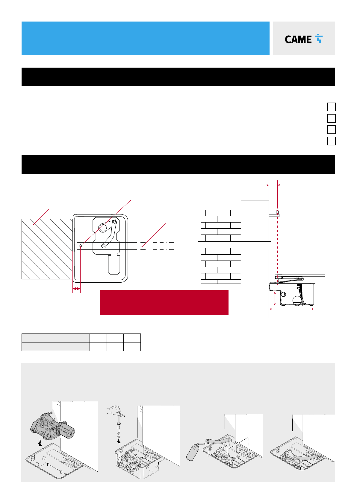
• Manually open the leaf.
• Position the gearmotor over the threaded pins
of the casing and fasten it.
• Lubricate the transmission lever.
• Fit the transmission lever as shown in the
drawings.
p. 7- Manual FA01302-EN - 02/2019 - © CAME S.p.A. - The contents of this manual may change, at any time, and without notice. - Original instructions
INSTALLATION
installed.
The drawings refer to the right-side gearmotor.
Preliminary operations
The preliminary operations for installation concern the foundation box installation and the release devices fastening. Refer to the installation manuals for
these products.
Setting up the gearmotor
Insert the closing limit-switch point adjustment screw into the gearmotor arm.
AGearmotor installed on the left
BGearmotor installed on the right
Fastening the gearmotor
Manually open the leaf.
Position the gearmotor over the threaded pins of the casing and fasten it.
p. 8- Manual FA01302-EN - 02/2019 - © CAME S.p.A. - The contents of this manual may change, at any time, and without notice. - Original instructions
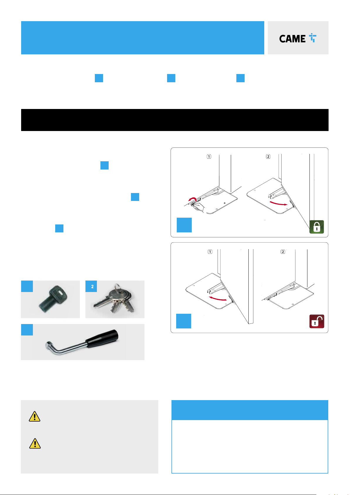
Manually close the gate leaf.
Loosen the adjusting screw of the closing limit-switch point until it touches the transmission lever.
Tighten the nut to lock the screw into position.
p. 8- Manual FA01302-EN - 02/2019 - © CAME S.p.A. - The contents of this manual may change, at any time, and without notice. - Original instructions
Manually close the gate leaf.
Loosen the adjusting screw of the closing limit-switch point until it touches the transmission lever.
Tighten the nut to lock the screw into position.
gate geometry
• It is always advisable to install an electric lock, to ensure reliable
closure of the gate.
• The installation of an electric lock is mandatory with gate leaves
longer than 2.5 m
Gate leaf length (m) 3.5 2.5 2
Gate leaf weight (kg) 400 600 800
LIMITS TO USE
Pillar
Leaf - closed
position
Hinge
67mm*
67mm*
100mm
330mm
*It is critical that the distance between the pillar
and the centre of the hinge be AT LEAST 67mm in
order for the motor to operate correctly.
For installations with gates opening outwards please refer to the main manual