SEA JACK Original instructions

LYRA, JACK 1600
67411785
Underground hydraulic operator
REV 00 - 03/2014
JACK JACK
CARRYING BOX
LYRA
INSTALLATION MANUALS
AND SAFETY INFORMATION
web site: www.sea-usa.com
e-mail: [email protected]
International registered trademark n. 2.777.971
SEA USA Inc.
10850 N.W. 21st unit 160 DORAL MIAMI
Florida (FL) 33172
Phone:++1-305.594.1151 Fax: ++1-305.594.7325
Toll Free: 800.689.4716

TABLE OF CONTENTS
International registered trademark n. 2.777.971
LYRA, JACK
67411785 REV 00 - 03/2014
A) SAFETY AND INSTALLATION INSTRUCTION....................................................................................3
GATE WARNINGS.................................................................................................................................5
PRECAUTIONS .....................................................................................................................................5
B) MECHANICAL INSTALLATION
FEATURES AND SPECIFICATIONS.....................................................................................................6
TECHNICAL DATA.................................................................................................................................6
DIMENSIONS ........................................................................................................................................7
NON CARRYING BOX INSTALLATION ................................................................................................7
INSTALLATION OF THE OPERATOR INSIDE THE NON-CARRYING BOX .......................................8
MOUNTING OF THE LEAF ON NON-CARRYING BOX .......................................................................8
HYDRAULIC UNIT BOX WALL INSTALLATION ...................................................................................9
BLEED CAP REPLACEMENT.............................................................................................................10
FORCE ADJUSTMENT ......................................................................................................................10
BRAKING REGULATION (where present) ..........................................................................................10
BLEEDING OPERATION.....................................................................................................................10
CARRYING BOX INSTALLATION........................................................................................................11
LEAF ASSEMBLING ON CARRYING BOX.........................................................................................12
INSTALLATION OF THE OPERATOR IN THE CARRYING BOX........................................................13
RELEASE MOUNTING .......................................................................................................................13
ADJUSTABLE MECHANICAL STOPS ................................................................................................13
CABLE LAYOUT ..................................................................................................................................14
RISK EXAMINATION ...........................................................................................................................15
PERIODICAL MAINTENANCE ............................................................................................................15
ACCESSORIES FOR JACK ................................................................................................................15
HYDRAULIC UNIT RELEASE SYSTEM ............................................................................................16
RELEASE SYSTEM OF THE LEAVES................................................................................................16
C) SALES CONDITIONS and WARRANTY ............................................................................................17
2

International registered trademark n. 2.777.971
Details
General
An appliance shall be provided with an instruction manual. The instruction manual shall give instructions for the installation,
operation, and user maintenance of the appliance.
The installation instructions shall specify the need for a grounding-type receptacle for connection to the supply and shall stress the
importance of proper grounding.
The installation instructions shall inform the installer that permanent wiring is to be employed as required by local codes, and
instructions for conversion to permanent wiring shall be supplied.
Information shall be supplied with a gate operator for:
a) The required installation and adjustment of all devices and systems to effect the primary and secondary protection against
entrapment (where included with the operator).
b) The intended connections for all devices and systems to effect the primary and secondary protection against entrapment. The
information shall be supplied in the instruction manual, wiring diagrams, separate instructions, or the equivalent.
Vehicular gate operators (or systems)
A vehicular gate operator shall be provided with the information in the instruction manual that defines the different vehicular gate
operator Class categories and give examples of each usage. The manual shall also indicate the use for which the particular unit is
intended as defined in Glossary, Section 3. The installation instructions for vehicular gate operators shall include information on
the Types of gate for which the gate operator is intended.
A gate operator shall be provided with the specific instructions describing all user adjustments required for proper operation of the
gate. Detailed instructions shall be provided regarding user adjustment of any clutch or pressure relief adjustments provided. The
instructions shall also indicate the need for periodic checking and adjustment by a qualified technician of the control mechanism
for force, speed, and sensitivity.
Instructions for the installation, adjustment, and wiring of external controls and devices serving as required protection against
entrapment shall be provided with the operator when such controls are shipped with the operator.
Instructions regarding intended installation of the gate operator shall be supplied as part of the installation instructions or as a
separate document. The following instructions or the equivalent shall be supplied where applicable:
a) Install the gate operator only when:
1) The operator is appropriate for the construction of the gate and the usage Class of the gate,
2) All openings of a horizontal slide gate are guarded or screened from the bottom of the gate to a minimum of 4 feet (1.22
m) above the ground to prevent a 2-1/4 inch (57.2 mm) diameter sphere from passing through the openings anywhere in
the gate, and in that portion of the adjacent fence that the gate covers in the open position,
3)All exposed pinch points are eliminated or guarded, and
4) Guarding is supplied for exposed rollers.
b) The operator is intended for installation only on gates used for vehicles. Pedestrians must be supplied with a separate access
opening. The pedestrian access opening shall be designed to promote pedestrian usage. Locate the gate such that persons will
not come in contact with the vehicular gate during the entire path of travel of the vehicular gate.
c) The gate must be installed in a location so that enough clearance is supplied between the gate and adjacent structures when
opening and closing to reduce the risk of entrapment. Swinging gates shall not open into public access areas.
d) The gate must be properly installed and work freely in both directions prior to the installation of the gate operator. Do not over-
tighten the operator clutch or pressure relief valve to compensate for a damaged gate.
e) (not applicable)
f) Controls intended for user activation must be located at least six feet (6’) away from any moving part of the gate and where the
user is prevented from reaching over, under, around or through the gate to operate the controls. Outdoor or easily accessible
controls shall have a security feature to prevent unauthorized use.
LYRA, JACK
67411785 REV 00 - 03/2014 3

g) The Stop and/or Reset button must be located in the line-of-sight of the gate. Activation of the reset control shall not cause the
operator to start.
h)A minimum of two (2) WARNING SIGNS shall be installed, one on each side of the gate where easily visible.
i) For gate operators utilizing a non-contact sensor:
1) See instructions on the placement of non-contact sensors for each Type of application,
2) Care shall be exercised to reduce the risk of nuisance tripping, such as when a vehicle, trips the sensor while the gate is
still moving, and
3) One or more non-contact sensors shall be located where the risk of entrapment or obstruction exists, such as the
perimeter reachable by a moving gate or barrier.
j) For a gate operator utilizing a contact sensor:
1) One or more contact sensors shall be located where the risk of entrapment or obstruction exists, such as at the leading
edge, trailing edge, and postmounted both inside and outside of a vehicular horizontal slide gate.
2) One or more contact sensors shall be located at the bottom edge of a vehicular vertical lift gate.
3) One or more contact sensors shall be located at the pinch point of a vehicular vertical pivot gate.
4) A hardwired contact sensor shall be located and its wiring arranged so that the communication between the sensor and
the gate operator is not subjected to mechanical damage.
5) A wireless contact sensor such as one that transmits radio frequency (RF) signals to the gate operator for entrapment
protection functions shall be located where the transmission of the signals are not obstructed or impeded by building
structures, natural landscaping or similar obstruction. A wireless contact sensor shall function under the intended end-
use conditions.
6) One or more contact sensors shall be located on the inside and outside leading edge of a swing gate.Additionally, if the
bottom edge of a swing gate is greater than 6 inches (152 mm) above the ground at any point in its arc of travel, one or
more contact sensors shall be located on the bottom edge.
7) One or more contact sensors shall be located at the bottom edge of a vertical barrier (arm).
Revised 56.8.4 effective February 21, 2008
Instruction regarding intended operation of the gate operator shall be provided as part of the user instructions or as a separate
document. The following instructions or the equivalent shall be provided:
IMPORTANT SAFETY INSTRUCTIONS
WARNING – To reduce the risk of injury or death:
ATTENTION: pour réduire le risque de dommages ou mort:
1. READAND FOLLOW ALL INSTRUCTIONS.
2. Never let children operate or play with gate controls. Keep the remote control away from children.
3.Always keep people and objects away from the gate. NO ONE SHOULD CROSS THE PATH OF THE MOVING GATE.
4. Test the gate operator monthly. The gate MUST reverse on contact with a rigid object or stop when an object activates the non-
contact sensors. After adjusting the force or the limit of travel, retest the gate operator. Failure to adjust and retest the gate
operator properly can increase the risk of injury or death.
5. Use the emergency release only when the gate is not moving.
6. KEEP GATES PROPERLY MAINTAINED. Read the owner’s manual. Have a qualified service person make repairs to gate
hardware.
7. The entrance is for vehicles only. Pedestrians must use separate entrance.
8. SAVE THESE INSTRUCTIONS.
International registered trademark n. 2.777.971
LYRA, JACK
67411785 REV 00 - 03/20144
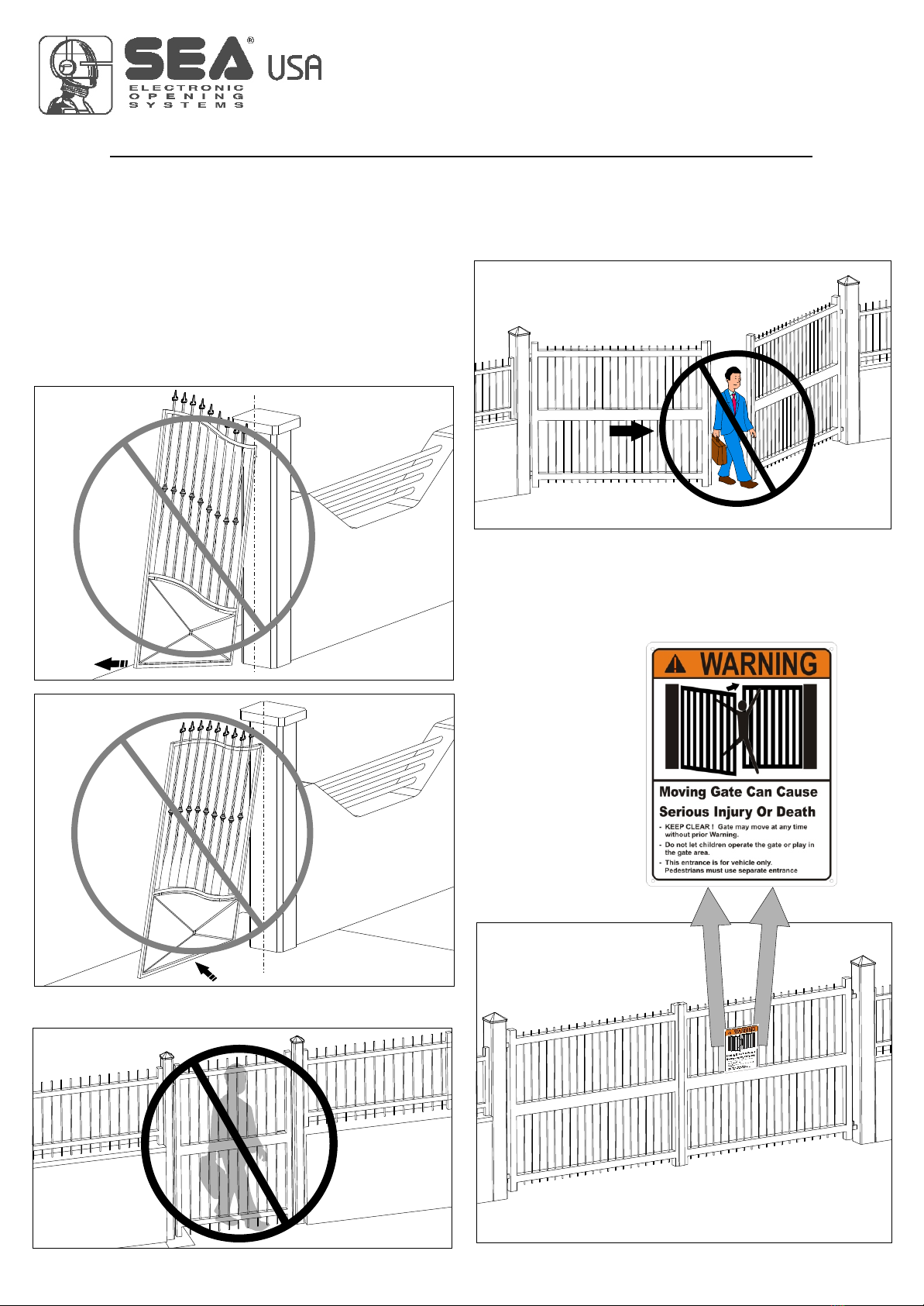
PRECAUTIONS
LYRA, JACK has been created for the automation of gates used by
vehicles only. Be aware to avoid the crossing of the gate path
because it is very dangerous for pedestrians (fig. 4).
Install the warning signs, on each side of the gate and in avisible
zone
Important:
For a higher security, SEA advices to install infrared photocells.
which informs the pedestrians about the danger they run when
passing or resting in the environment of the gate (fig. 5).
GATE WARNINGS AND PRECAUTIONS
- Not for pedestrian opening
Fig. 4
Fig. 1
Fig. 2
Fig. 3
Fig. 3
Fig. 5
International registered trademark n. 2.777.971
GATE WARNINGS
The first thing to check is that the gate is in good running order as
follows:
D. the upper hinge alone is sufficient to install the unit; those which
are unnecessary can be eliminated (the lower and that in the
middle if exists)
A. (Make sure that) the fixed and moving parts of the gate are strong
and non-deformable;
B. the weight of each gate leaf must not exceed 1600 Pound;
C. the hinges and general structure must be in good condition and the
gate must move smoothly throughout its travel;
LYRA, JACK
67411785 REV 00 - 03/2014 5
JACK 1600 JACK 1600
Note: The frequency of use is valid only for the first hour at 68°F
room Temperature.
Jack 1600 Lyra
13,12 feet
1600 pound
12
13
14
15
15
16 17
Fig. 8
123
4
5
Fig. 6
6
7
8
9
10
11
CARRYING BOX
Fig. 7
120 V~
220W
500 rpm
45
-4°F +131°F
130°
56 da N
60 µF
1600 Pound
IP67
17,63 Pound
-
REV 00 - 03/2014
100° - 140° - 180° -
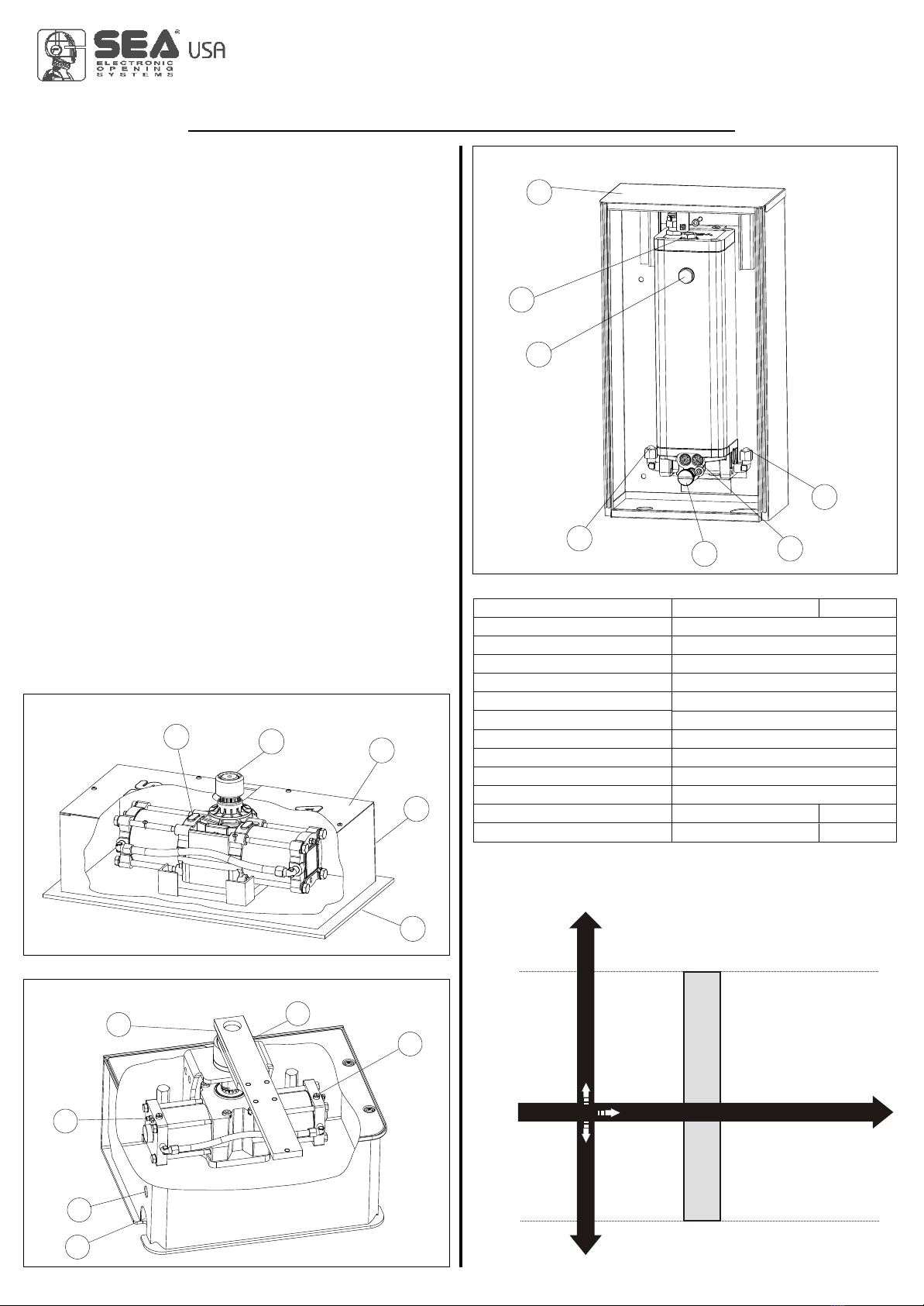
MAIN PARTS NOMENCLATURE
TECHNICAL DATA
Power supply
Motor Power
Motor rotation speed
Cycles hour (with a 20°C temp.)
Operating temperature
Thermal protection intervention
Max torque
Starting capacitor
Weight
Protection class
Maximum weight of the gate
Max leaf weight
Max leaf width
Underground hydraulic operators
GRAPHIC FOR THE USE OF
JACK 1600 OPERATORS
1Jack
2 Broached bush
3Box lid
4Box
5Foundation base
6Braking screw
(where provided)
7Exit hole for electric cables
8Water draining hole
adjusting
9 Air bleed screw
10
11
12 Hydraulic unit box
13 Oil charge cap
14
15 Hydraulic plug
16 Release screw
17 By pass valves
Greaser
Crank
Oil level cap
NON-CARRYING BOX
LYRA HYDRAULIC UNIT
Jack rotation angle
1. FEATURES AND SPECIFICATIONS
The LYRA JACK consists of a hydraulic pump and a hydraulic
jack. The jack is placed inside a non carrying or carrying box
(inox only for carrying box).
The pump unit casing, which is used as an oil tank, contains the
electric motor, fluid pump, distributor and hydraulic oil. It is also
provided with an adjustable slowing-down device in the two
stop phases of the leaf (versions with slow-down only).
The wheeling unit is composed by a double piston connected to
a rack which engages with the pinion of the leaf dragging shaft.
Gates up to 6,56 feet long can be securely locked using the
operators internal hydraulic locking system, thus ensuring
perfect keeping in closing and in opening. For gate in excess of
stated value: A hydraulic non locking operator should be used in
conjunction with a separate electrical locking device to ensure
keeping in closing.
On the operators with hydraulic slow down it is present
only during the last 15° of rotation. The system comes with a
release which allows the manual opening of the leaves in case of
power failure.
MECHANICAL INSTALLATION
International registered trademark n. 2.777.971
LYRA, JACK
674117856
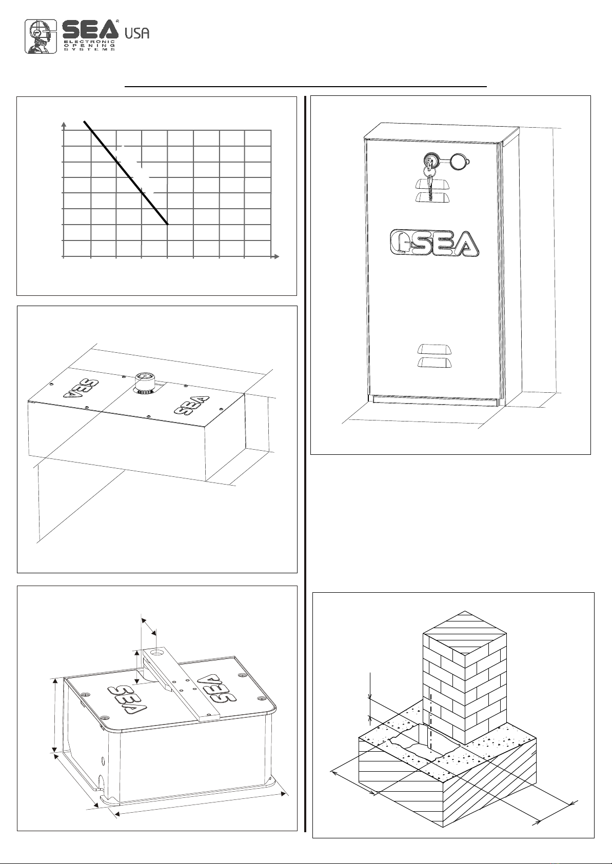
Fig. 12
23,62
81 1 , 1
6,30
Dimensions (inches)
15,78
8,26
4,76
Dimensions (inches)
Fig. 11
15,74 -17,32
4,76
8
6
1600
1543
1323
1102
882
661
441
220
00 6,5 8 10 13 16 20 23 26
J 0
ACK 160
15,74 inches ®100° - 140°
17,32 inches ®180°
Dimensions (inches)
Fig. 9
Fig. 10
7,40
612,0
16,14
2,67
2,16
Dimensions (inches)
REV 00 - 03/2014
Weight
(Pound)
Leaf length (Feet)
GRAPHIC (A)
CARRYING BOX
NON-CARRYING BOX
LYRA HYDRAULIC UNIT
2. NON-CARRYING BOX INSTALLATION
2.1. The excavation which contains the non-carrying box must
have the approximate dimensions mentioned in Fig. 12. For a
correct placing, it is obligatory to closely follow the quote of 2,16
inches which corresponds to the minimum distance of the
rotation axis from the pillar.
MECHANICAL INSTALLATION
International registered trademark n. 2.777.971
LYRA, JACK
67411785 7
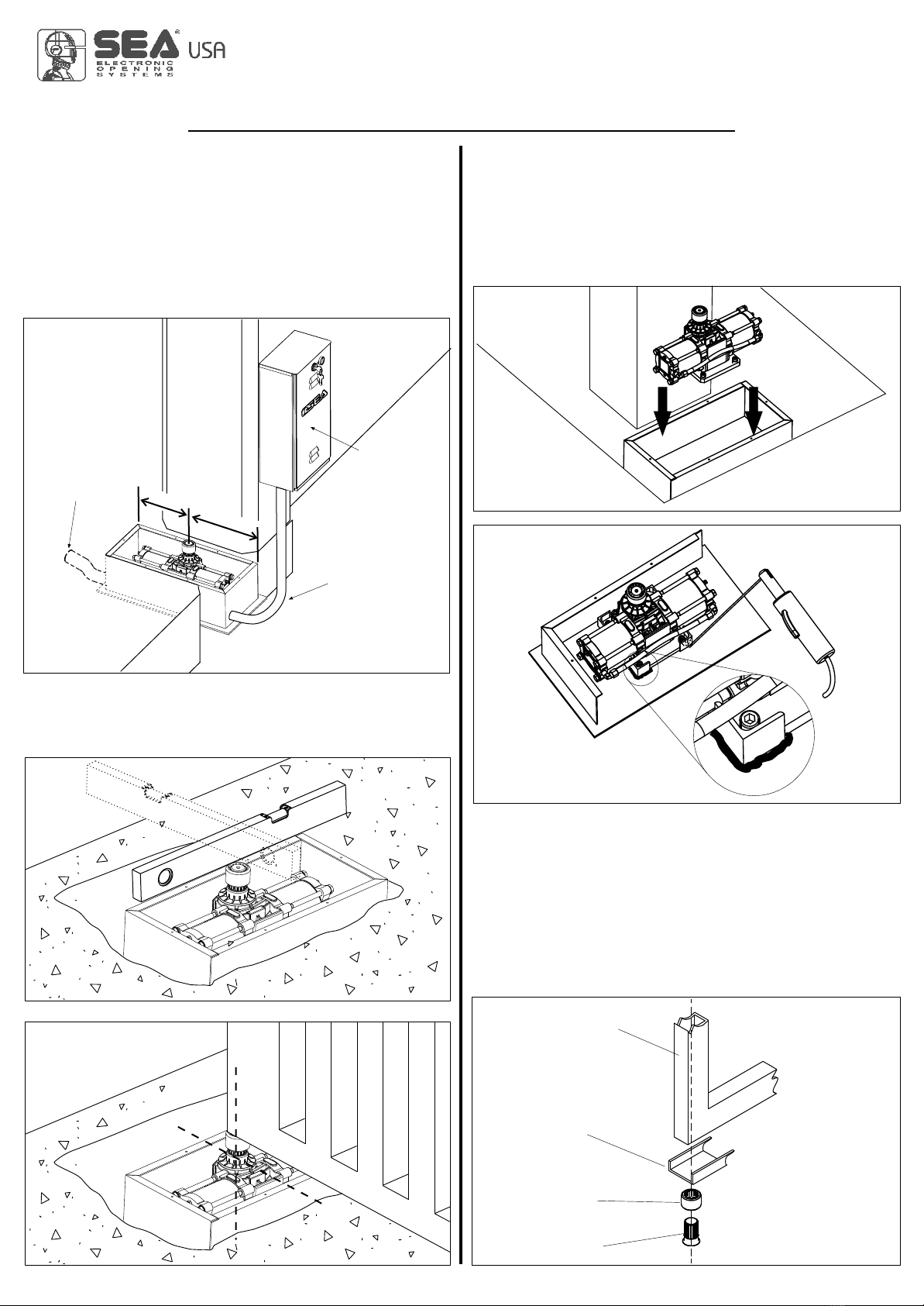
Fig. 14
Fig. 15
Fig. 18
Fig. 16
Fig. 17
REV 00 - 03/2014
Fig. 13
=
=
Flexible pipe
for water
draining
2.2. Inside the excavated pit you have to plan:
- rain water drainage;
- a water waste pipe in flexible plastic of about 1,57 inches of
diameter to put inside the provided hole of the box before it is
concreted (Fig. 13). It must be brought to the drain of the
sewer line;
- a sheath for the passage of the hydraulic tubes of about 1,25
inches of diameter which must be brought to the proximity of
the hydraulic unit box (Fig. 13).
2.3. Before concreting the box, use a level to make it perfectly
horizontal to the ground (Fig. 14) and perpendicular to the axis of
the gate (Fig. 15).
Hydraulic tubes
sheath
Hydraulic unit
Pivot
Bush
U-shaped bar
Leaf
4. MOUNTING OF THE LEAF ON NON-
CARRYING BOX
4.1. Insert the broached bush on the shaft of the jack.
Turn the shaft of the jack toward closing until it stops.
WARNING: For operators with brake make sure that the jack
has reached the stop and not the beginning of the
slowdown.
4.2. Go back about 5° and weld the bush to the U-shaped bar
(not supplied) and to the leaf of the gate (Fig. 18).
3. INSTALLATION OF THE OPERATOR
INSIDE THE NON-CARRYING BOX
3.1. Place the jack inside the foundation box (Fig.16)
positioning the axis of the output shaft aligned with the axis of
the hinge of the gate and weld the four angular ends to fix the
same (Fig. 17).
MECHANICAL INSTALLATION
International registered trademark n. 2.777.971
LYRA, JACK
674117858
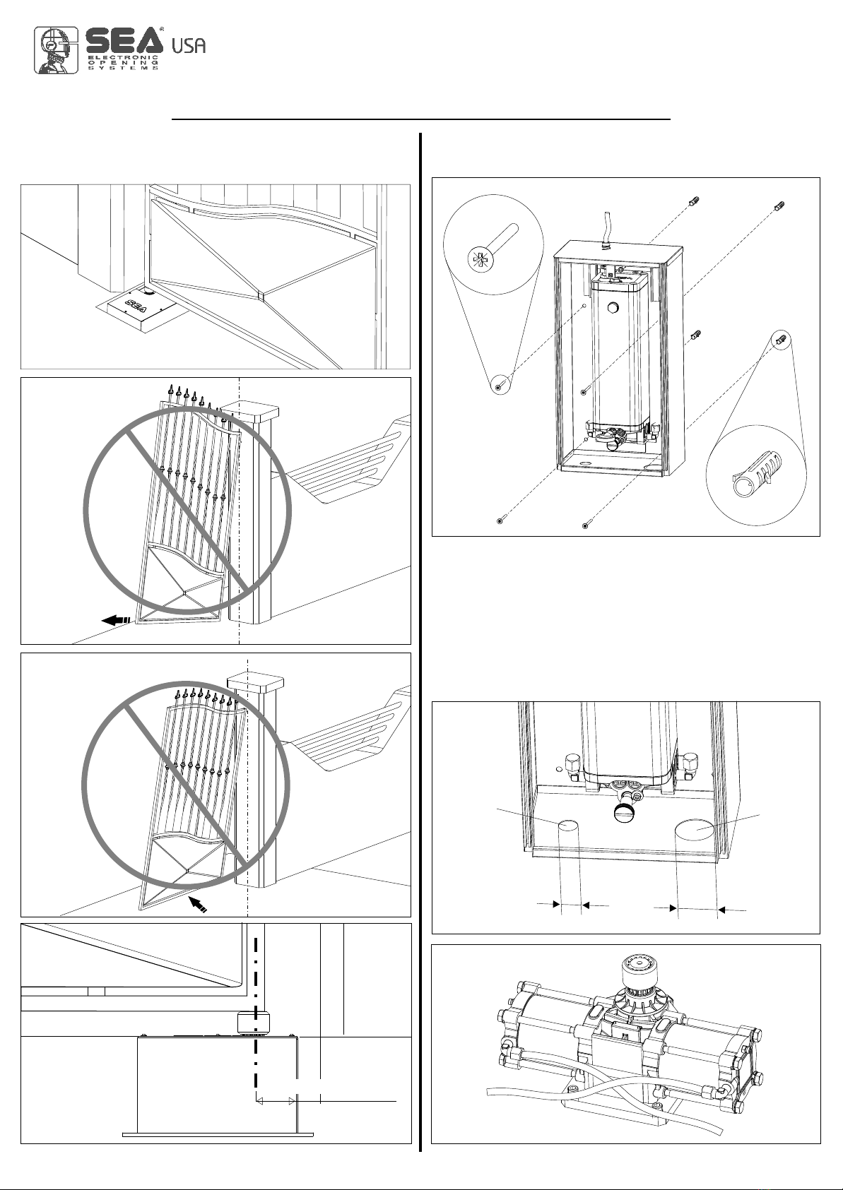
Fig. 19
2,16 inches min.
Fig. 20
Fig. 21
Fig. 22
REV 00 - 03/2014
1,57’’
0,78’’
Fig. 23
Fig. 24
Fig. 25
4.3. Be careful not to place the leaf outside the axis (Fig. 20
and 21) and make sure that the shaft corresponds to the
rotation axis of the jack.
5. HYDRAULIC UNIT BOX WALL
INSTALLATION (Fig.23)
5.1. Connect the hydraulic tubes with the hydraulic unit and the
jack (Fig.25, Fig.26, Fig.27).
After having installed the box, the gate and the operator, try to
slowly move the gate by hand to make sure that there are no
irregular frictions and that the movement is uniform for the whole
range.
Notice: To do this last operation, release the operator as
described in the related paragraph.
Hydraulic
tubes
inlet
Cable
inlet
MECHANICAL INSTALLATION
International registered trademark n. 2.777.971
LYRA, JACK
67411785 9
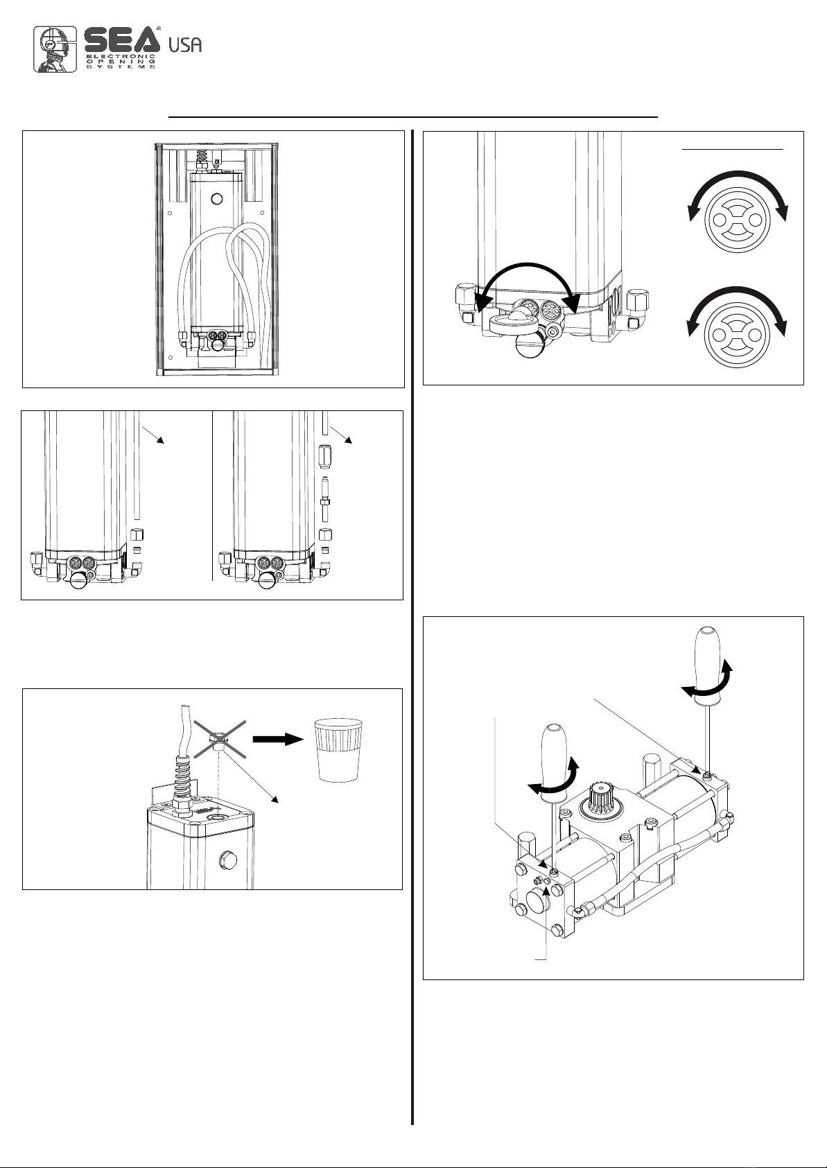
8. BRAKING REGULATION (where present)
8.1. It is possible to regulate the leaf slowdown in opening and in
closing, through the braking adjusting screw (Fig. 30).
8.2.To regulate slowdown operate as follow:
- Loosen the blocking screw of braking regulation;
- Act on the adjusting screw clockwise to have a higher braking
and a speed decrease;
- Act on the adjusting screw anti-clockwise to have a lower
braking and a speed increase;
-After the regulation fix the blocking screw of braking regulation.
On the operators with hydraulic slow down it is prensent
only during the last 15° of rotation.
Fig. 30
+
-
+
-
Fig. 27
Fig. 26
REV 00 - 03/2014
Fig. 28
-+
By-Pass Valves
Fig. 29
+-
Grey
n
e
t
m
t
s
i
u
n
j
d
o
a
p
e
e
n
c
r
i
n
o
g
F
+-
Yellow
e
t
n
m
t
s
i
u
n
j
d
c
a
l
o
e
s
c
r
i
n
o
g
F
Braking regulation screw
Opening/closing
Blocking screw for
braking regulation
Copper
tube
Flexible
tube
6. BLEED CAP REPLACEMENT (Fig.28)
Remove the red cap and replace it with the supplied black one
after startup.
7. FORCE ADJUSTMENT
If necessary the thrust force of the leaf can be adjusted by the
two adjusting screws (grey and yellow) placed on the front lower
place of the hydraulic pump unit (Fig. 29).
*The operator is adjusted at 33 pound force ex works so to
guarantee the anti-crush safety.
We recommend to adjust it only in case of necessity.
Red cap
9. BLEEDING OPERATION
During the connection phase between hydraulic unit and jack, air
will inevitably enter into the system and cause an irregular
operation of the operator. The irregular operation shows by an
abnormal movement of the leaf and excessive noise during
operation. To solve this problem it is necessary to proceed as
follows:
MECHANICAL INSTALLATION
International registered trademark n. 2.777.971
LYRA, JACK
6741178510
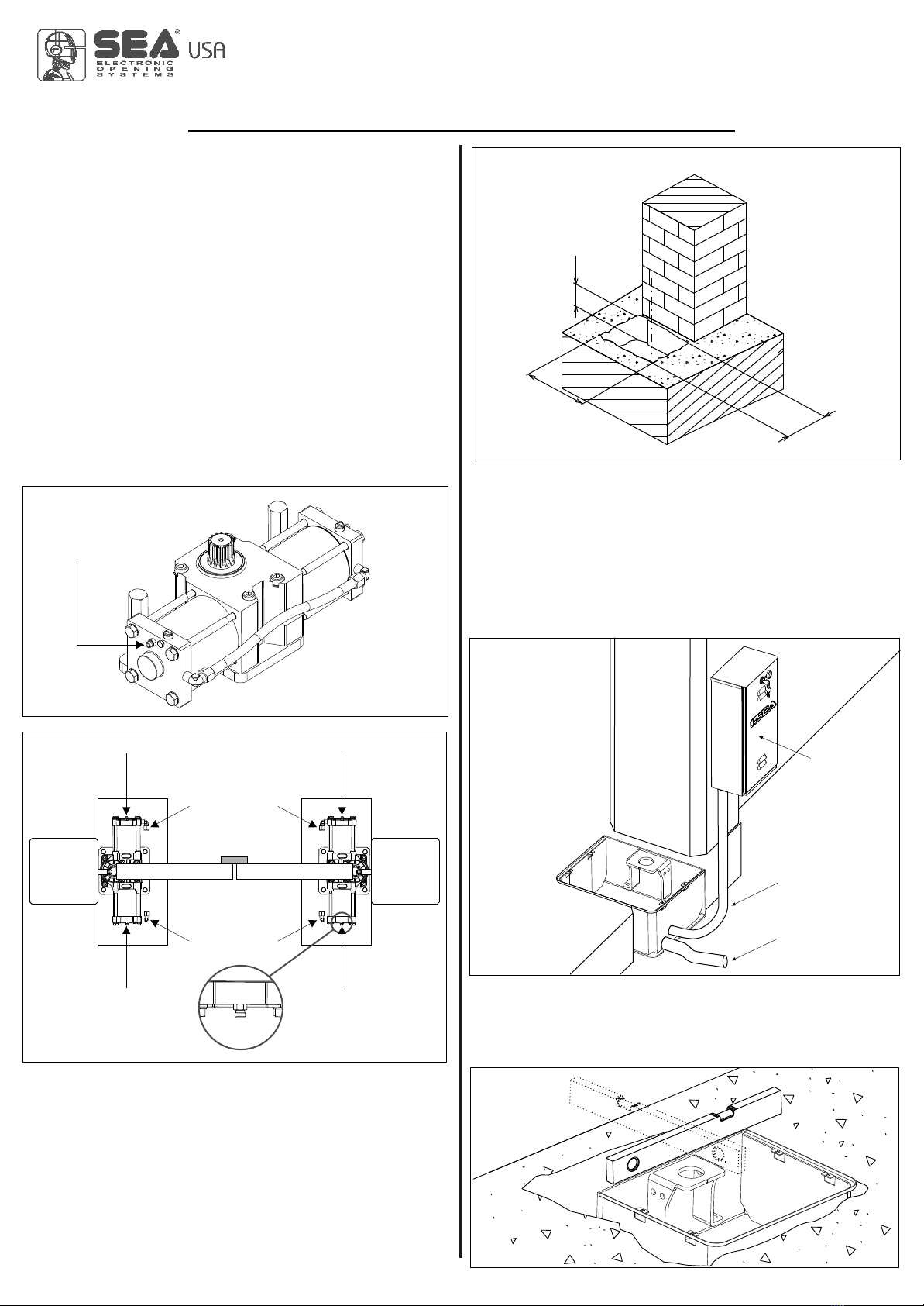
Air bleed screw
Fig. 31
CLOSING
OPENING EXT
INT
A A
B B
Fig. 32
Fig. 33
23,62
17,71
8,46
Dimensions (inches)
10. CARRYING BOX INSTALLATION
10.1. The hole which contains the carrying box must have the
approximate dimensions mentioned in Fig. 33.
For a correct placing, it is obbligatory to follow closely the quote
of 2,16 inches which corresponds to the minimum distance of
the rotation axis from the pillar.
Fig. 35
10.3. Before concreting the carrying box, use a level to make it
perfectly horizontal to the ground (Fig. 35) and perpendicular to
the axis of the gate (Fig. 36).
The axis of the upper hinge of the gate must correspond exactly
to the axis of the carrying box shaft.
REV 00 - 03/2014
Fig. 34
a) command opening of the gate;
b) during opening of the gate, loosen the air bleed screw related
to opening (Fig.32-rif.A);
c) release any air from the hydraulic circuit until non-emulsified
oil appears;
d) tighten the air bleed screw before the operator completes the
opening cycle;
e) command closing of the gate;
f) during closing of the gate, loosen the air bleed screw related to
closing (Fig.32-rif.B);
g) release any air from the hydraulic circuit until non-emulsified
oil appears;
h) tighten the air bleed screw before the operator completes the
closing cycle.
It is recommended to repeat this operation on both air bleed
screws at intervals of 2/3 opening and closing cycles.
i) Replace the oil from the oil filler cap. Any top-ups should be
performed only with oil SEA0x29 (supplied).
10.2. Inside the excavated pit you have to plan:
- rain water drainage;
- a water waste pipe in flexible plastic of about 1,57 inches of
diameter to put inside the provided hole of the box before it is
concreted (Fig. 34). It must be brought to the drain of the
sewer line;
- a sheath of about 1,25 inches diameters for the passage of
hydraulic tubes must be brought to the proximity of the
hydraulic unit box (Fig. 34).
Hydraulic
unit
Hydraulic tubes
sheath
Flexible pipe
for water
draining
MECHANICAL INSTALLATION
International registered trademark n. 2.777.971
LYRA, JACK
67411785 11

Fig. 38
Fig. 37
Fig. 41
2,16 inches min.
Fig. 40
11. LEAF ASSEMBLING ON CARRYING BOX
Before installing the gate make sure that the concrete has
hardened into the foundation hole.
11.1. Position the leaf of the gate on the leaf device making
reference to the rotation axe of the leaf hinge (Fig. 38);
11.2. Weld with care the leaf device to the leaf of the gate
realizing a tract fixation of ca. 1,18-1,57 inches along the surface
of the contact, avoiding the welding next to the threaded
Fig. 36
10.4. Introduce the buckle of creeping in the box and fix it with
the special screws (Fig. 37).
10.5. Insert the units as in Fig. 37.
N.B.: During the insertion of the units lubricate
them with the supplied grease.
holes, furthermore it is necessary to respect the perpendicularity
to the axe of rotation (Fig. 39)
Fig. 39
11.3. Be careful not to place the leaf outside the axis (Fig. 20
and 21), but make sure the shaft corresponds to the hinge
rotation axis remembering that the minimum distance from the
pillar is 2,16 inches (Fig. 41).
REV 00 - 03/2014
Leaf device
Leaf rotation axe
Leaf
Crank shaft Crank
MECHANICAL INSTALLATION
International registered trademark n. 2.777.971
LYRA, JACK
6741178512
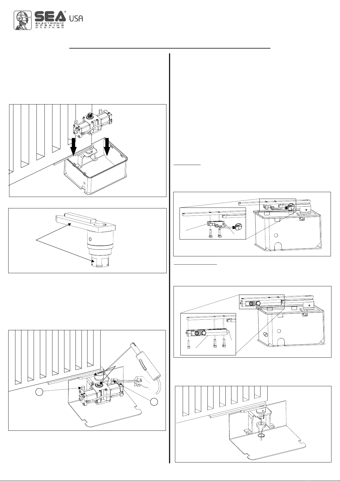
RELEASE PLUS
13.2. Grease the hinge (A) and mount the release system under
the leaf device using the 5 furnished screws (Fig. 46).
Fig. 42
Fig. 44
2
Fig. 43
Fig. 45
A
12. INSTALLATION OF THE OPERATOR IN
THE CARRYING BOX
12.1. Insert manually the operator into the carrying box (Fig. 42)
also insert the splined shaft of the operator into the splined bush
of the box and fix the operator with the special screws as in
Fig.44.
N.B.: It is advisable to weld the crank with the crank shaft after
having also installed the Jack, to use the whole available run and
the point of beginning of the desired slowdown (version with
hydraulic slowdown).
Before welding, make sure that one of the level of the crank shaft
corresponds with a side of the crank (see fig.43 and 44) to
guarantee the maximum angle with the mechanical stops Kit.
N.B.: If the Jack is not installed immediately but in a second time,
it is recommended to weld the crank shaft and the crank during
the installation of the Jack.
Carry out the electrical connections to the control unit as
described in the instructions supplied with SEA control unit.
Fig. 46
A
Fig. 47
REV 00 - 03/2014
1
Release
Release Plus
14. ADJUSTABLE MECHANICAL STOPS
12.1. Connect the hydraulic tubes with the hydraulic unit and the
jack (Fig.25, Fig.26, Fig.27).
After the installation of the above mentioned carrying box, of the
gate and the operator, try to move the gate slowly by hand
verifying that there are no irregular frictions and that the
movement is uniform for the whole range.
Notice: To do this last operation, release the operator as
described in the related paragraph.
13. RELEASE MOUNTING
For the Jack are foreseen two types of release:
RELEASE (with personalised key) and RELEASE PLUS
(with DIN key).
RELEASE
13.1. Grease the hinge (A) and mount the release system under
the leaf device using the 4 furnished screws (Fig. 45).
MECHANICAL INSTALLATION
International registered trademark n. 2.777.971
LYRA, JACK
67411785 13
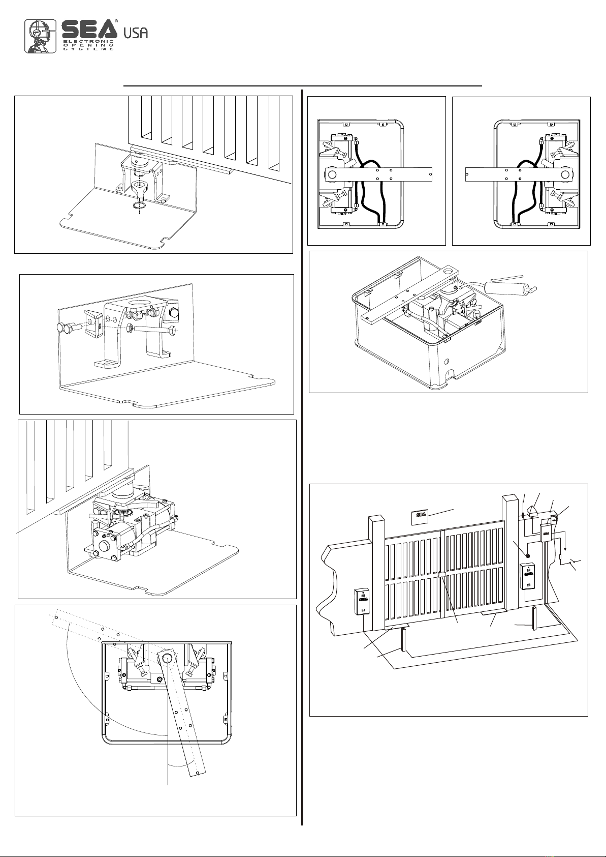
Fig. 49
Fig. 48
Fig. 51
0
-15°
105°
Fig. 52 Fig. 53
Fig. 50
When putting in function the installation it is peremptory to
lubricate the box as in Fig. 54 until the grease comes out.
se grease typeDIN 51502 KP 2 N-20 - K 2 K-20).(U
Fig. 54
Fig. 55
1
23
4
2
5
6
789
10
11
15. CABLE LAYOUT (Fig. 55)
REV 00 - 03/2014
Max. Angle with mechanical stops kit
RIGHT
LEFT Outside
Inside
Outside
Inside
1) Warning notice
2) Jack 1600
3) Left photocell
4) Right photocell
8) Electronic control unit
9) Receiver
10) Differential switch
11) Electric lock (SB version only)
5) Key switch
6) Antenna
7) Flashing warning lamp
MECHANICAL INSTALLATION
International registered trademark n. 2.777.971
LYRA, JACK
6741178514

Fig. 56
REV 00 - 03/2014
17. PERIODICAL MAINTENANCE
Check the oil level
(Trasparent cap n.14 in Fig. 8) Annual
Change the oil
Verify the functionality of the by-pass valves
(check the force in opening and closing)
Check the release function
Verify the slowdown regulation (where present)
Check the correct drain of the rainwater
Check the integrity of the connection cables
Grease all the moving parts
Grease the rotation axis of the box as in Fig.54
4 years
Annual
Annual
Annual
Annual
Annual
Annual
Annual
SAFETY GATE
18. ACCESSORIES FOR JACK
CARRYING BOX INOX
RELEASE
RELEASE PLUS
KIT MECHANICAL STOP
MECHANICAL INSTALLATION
International registered trademark n. 2.777.971
16. RISK EXAMINATION
The points pointed by arrows are potentially dangerous.
The installer must take a thorough risk examination to prevent
crushing, conveying, cutting, grappling, trapping so as to
guarantee a safe installation for people, things and animals. (
).
in fig. 56
Re.
Laws in force in the country where installation has been made
As for misunderstandings that may arise refer to your area
distributor or call our help desk. These instructions are part of the
device and must be kept in a well known place.The installer shall
follow the provided intructions thoroughly.
products must only be used to automise doors, gates and lwings.
Any initiative taken without explicit authorization
will preserve the manufacturer from whatsoever responsibility.
The installer shall provide warning notices on not assessable
further risks. in its relentless aim to improve the
products, is allowed to make whatsoever adjustment without
giving notice. This doesn’t oblige to up-grade the
past production. can not be deemed responsible
for any damage or accident caused by product breaking, being
damages or accidents due to a failure to comply with the
instructions herein. The guarantee will be void and the
manufacturer responsibility will be nullified if
original spare parts are not being used.
Packaging
materials such as plastic bags, foam polystyrene, nails etc must
be kept out of children’s reach as dangers may arise.
SEA USA Inc.
SEA USA Inc.
SEA USA Inc.
SEA USA Inc.
SEA USA Inc.
SEA USA Inc.
The electrical installation
shall be carried out by a professional technician who will release
documentation as requested by the laws in force.
LYRA, JACK
67411785 15

20. RELEASE SYSTEM OF THE LEAVES
RELEASE
20.1. To release act as follows:
-Insert the enclosed key into the keyhole (S) and turn the handle
about 180° against the centre of the gate (Fig. 58) .
-Keep the key locked and move the leaf, now turn back the key to
the normal position and extract it.
20.2. To stop again act as follows:
-Move the leaf until the lock has coupled again.
S
Fig. 58
180°
RELEASE PLUS
20.3. To release act as follows:
-Insert the enclosed key into the keyhole and turn it about 90° in
clockwise direction (Fig. 59).
- Pull the key against the external of the release making come
out the handle of the lock until it reaches the stop (Fig.60).
- Move the leaf and make return the handle of the release in its
original position and extract the key.
21.4. To stop again act as follows:
-Move the leaf until the lock has coupled again.
Fig. 59
90°
Stop
Release handle
Fig. 60
Hydraulic pump
manual release
Fig. 57
REV 00 - 03/2014
To the attention of users and technicians
Release Lock
19. HYDRAULIC UNIT RELEASE SYSTEM
19.1. To release do as follows:
- Open the door with the delivered special key.
- Turn the release srew, placed on the hydraulic unit.about 90°
into anti-clockwise direction.
- Move the beam with the hand.
19.2. To re-lock do as follows:
- Turn the release screw, placed on the hydraulic unit.about 90°
into clockwise direction
- Close the door.
½ turn
MECHANICAL INSTALLATION
International registered trademark n. 2.777.971
LYRA, JACK
6741178516

GENERAL WARNING: Installation must be realized using parts and accessories approved by SEA. SEA is not
responsible for incorrect installations and/or non-compliance with safety standards according to the law in-force. SEA is in
no way liable for any damages and/or malfunctioning due to using parts and accessories non-compliant with the UL325
safety standards.
ORDERS: Orders are processed upon approval by SEA. Buyers must confirm orders by sending a written Purchase
Orders to SEA. Purchase Orders are intended as confirmation of orders and binding for the buyer, which accepts SEA
sales condition.
QUOTATION: Quotation and special offers with a non-specified duration expires automatically after 30 days.
PRICES: Prices are based on the Price List in force. Discounts and quotation from Sales Rep. and other selling branches
must be approved by SEA. Prices are F.O.B SEA Warehouse in Miami and do not include shipments costs. SEA reserves
the right to modify the price list at any time and provide notice to its sales network.
PAYMENT: Method of payments and terms are notified by SEAand displayed on the commercial invoice.
DELIVERY: The delivery time on the invoice is not binding and represents an estimated delivery. Shipments costs will be
charged to the buyer and SEAis not responsible for delays and/or damages occurred to the products during shipment.
COMPLAINS: Complains and/or claims must be notified to SEA within 7 business days after receiving the products.
Claims and complains must be supported by original documents. Customer must contact the factory for instructions and
authorization. Merchandise returned for credit must be current, uninstalled and unused and returned in its original
packaging. Freight must be pre-paid on all authorized returns.
REPAIRS: Repairs and parts are subject to the availability in stock. Shipment of products for repairs must be pre-paid by
the customer. Products shipped without authorization, sender’s details and description of the problems will be refused.
Customers must contact SEAfor instructions.
WARRANTY: for the original buyer only:
Hydraulic and oil-bath motors: 36 months warranty from the date of invoice on manufacturing, assembling and
workmanship defects.
Electro-mechanic motors and electronic control systems: 24 months warranty from the date of invoice on manufacturing,
assembling and workmanship defects.
Lepus and Full Tank Standard model: 60 months warranty from the date of invoice on manufacturing, assembling and
workmanship defects.
No warranty will be recognized for damages due to incorrect installation and/or improper use for which the product was
intended. SEA warranty obligations shall be limited to repair or replace the defective product/parts at SEA option, upon
examination of the products by SEAtechnical Staff. All replaced parts must remain property of SEA. The warranty status of
the product remains an unquestionable assessment of SEA. Buyer must ship pre-paid defective products. Products under
warranty will be returned pre-paid by SEA. Recognized defects, whatever their nature, will not produce any responsibility
and/or damage claims to SEA USA Inc and SEA s.r.l. Warranty shall not cover any required labor activities. Warranty will in
no case be recognized if alterations and any other changes will be found on products. Warranty will not cover damages
caused by carriers, expendable materials and faults due to improper use with the products specifications. No indemnities
are recognized during repairing and/or replacing of the products under warranty. SEA USA Inc. and SEA s.r.l. decline any
responsibility for damages to person and objects deriving from non-compliance with safety standards, installation
instructions or use of the products sold. It is intended that warranty will be recognized only on products bought through the
SEA authorized network. Products must be installed by professionals. No warranty will be recognized if products are
installed directly by the final user. Warranty does not apply in case of unexpected events such as fire, flood, electrical
power surge, lightning, vandalism and others.
SEA USA Inc. is not responsible for errors in technical information printed in catalogs and installation manuals.
SALES CONDITIONS and WARRANTY
International registered trademark n. 2.777.971
LYRA, JACK
67411785 REV 00 - 03/2014 17


web site: www.sea-usa.com
e-mail: [email protected]
SEA USA Inc.
10850 N.W. 21st unit 160 DORAL MIAMI
Florida (FL) 33172
Phone:++1-305.594.1151 Fax: ++1-305.594.7325
Toll Free: 800.689.4716
®
International registered trademark n. 2.777.971
This manual suits for next models
2
Table of contents
Other SEA Gate Opener manuals

SEA
SEA GATE 1 DG R2BF User manual

SEA
SEA Libra Mini Tank User manual

SEA
SEA SCUTI User manual

SEA
SEA TORG Series Instruction manual

SEA
SEA MARK TANK E 270 User manual

SEA
SEA FLIPPER User manual

SEA
SEA Cougar 270 User manual

SEA
SEA ARM Instruction manual

SEA
SEA GATE 2 DG INVERTER User manual

SEA
SEA HALF TANK User manual

SEA
SEA COMPACT 200 CP Instruction manual

SEA
SEA Boxer 1000 User manual

SEA
SEA KITE User manual

SEA
SEA LYRA User manual

SEA
SEA LYRA Instruction manual

SEA
SEA UNIGATE 1I User manual

SEA
SEA SUPER FULL TANK 20 G6 380V User manual

SEA
SEA SATURN User manual

SEA
SEA EASY 20 User manual

SEA
SEA SURF 350 Reversible User manual


