CAME U 8700 User manual

Documentazione
Tecnica
S61
rev. 1.5
04/2001
©
CAME
CANCELLI
AUTOMATICI
119DS61
CANCELLI AUTOMATICI
SET
COMPLETE
U8700
Composition set:
1 - Groupe
motoréducteur
2 - Armoire de
commande
3 - Récepteur radio
4 - Photocellule
5 - Sélecteur externe
6 - Serrure électrique
7 - Clignotant
8 - Antenne
9 - Emetteur
Das Montageset enthält:
1 - Antriebsmotor
2 - Steuergerät
3 - Funkempfänger
4 - Photozellen
5 - Außenmontage-
Schalter
6 - Elektroschloß
7 - Blinkleuchte
8 - Antenne
9 - Funksender
Composición set:
1 - Conjunto
motorreductores
2 - Cuadro de mando
3 - Radioreceptor
4 - Fotocélules
5 - Selector exterior
6 - Cerradura eléctrica
7 - Lámpara
8 - Antena
9 - Trasmisor
Set composition:
1 - Gear motor unit
2 - Control panel
3 - Radio receiver
4 - Photocells
5 - Protruding switch
6 - Electric lock
7 - Flasher
8 - Antenna
9 - transmitter
Composizione set:
1 - Gruppo
motoriduttore
2 - Quadro comando
3 - Ricevitore radio
4 - Fotocellule
5 - Selettore esterno
6 - Elettroserratura
7 - Lampeggiatore
8 - Antenna
9 - trasmettitore
Impianto tipo
Standard installation
Installation type
Standard Montage
Instalación tipo
CONFEZIONE COMPLETA PER L'AUTOMAZIONE DI CANCELLI PEDONALI E/O CARRABILI A 2 ANTE
A BATTENTE DI LARGHEZZA MASSIMA FINO A 1.60 M PER ANTA CON MOTORIDUTTORE F500
COMPLETE SET FOR POWERING PEDESTRIAN AND/OR DRIVEWAY GATES HAVING TWO SWINGING
GATE WINGS WITH MAXIMUM WIDTH OF 1.60 M EACH WITH F500 GEARMOTOR
SET COMPLET POUR L'AUTOMATISATION DE PORTAILS A BATTANT POUR PIETONS ET/OU
VOITURES A DEUX VANTAUX AYANT UNE LARGEUR MAXIMALE DE 1.60 M CHACUN AVEC
MOTORÉDUCTEUR F500
KOMPLETTES MONTAGESET FÜR DEN ANTRIEB VON ZWEIFLÜGELIGEN EINGANGS- UND/ODER
EINFAHRTSTOREN MIT EINER HÖCHSTBREITE VON 1.60 M PRO TORFLÜGEL MIT F500
GETRIEBEMOTOR
CONJUNTO COMPLETO PARA LA AUTOMATIZACION DE PUERTAS PEATONALES Y/O CARRILES A
DOS HOJAS BATIENTES DE LONGITUD MAXIMA DE HASTA 1.60 M CADA HOJA CON
MOTORREDUCTOR F500
4
52
3
1
64
1
9
7
* 2 x 1.5
2 x 1.5
2 x 1
2 x 1
4 x 1
RG58
*2x1,5
3x1,5 / 230V
2 x 1
8
Câbles d'alimentation moteur:
2 x 1.5 mm2jusqu'à20 m
2 x 2.5 mm2jusqu'à30 m
Antriebsmotor-Verbindungskabel:
2 x 1.5 mm
2
bis 20 m
2 x 2.5 mm
2
bis 30 m
Cables de alimentación motores:
2 x 1.5 mm2hasta 20 m
2 x 2.5 " " 30 m
Power wires to motor:
2 x 1.5 mm
2
up to 20 m
2 x 2.5 mm
2
up to 30 m
Cavi di alimentazione motori:
2 x 1.5 mm2fino a 20 m
2 x 2.5 mm2fino a 30 m
* 2 x 1,5

2
B= 350
A
C
E
ASSI E INGOMBRI -
CENTRE LINES AND EXTERNAL DIMENSIONS
- AXES ET ENCOMBREMENTS
ACHSEN & ABMESSUNGEN
- EJES Y DIMENSIONES MÁXIMAS
i= 230 mm. max
con apertura a 90°
with 90°opening angle
avec ouverture à90°
mit 90°-Öffnungwinkel
con apertura a 90°
Larghezza anta
Width of gate wing
Largeur du vantail
To r b r ei te
Ancho hoja
m.
Peso anta
Weight of gate wing
Poids du vantail
Torgewicht
Peso hoja
Kg.
0,80 150
1,20 125
1,60 100
A C
40÷150 0÷150

3
76
100
80
17,5
50
80
2 x ø 6,5
3 x ø 8,5
56
Staffa di aggancio braccio snodato
Bracket articulated arm
Etriere de fixation du bras articulés
Armbefestigungs-Bügel
Estribo de enganche brazo articolados
Flangia attacco motoriduttore
Gear motor mounting flange
Bride de raccord du motoréducteur
Getriebemotorbefestigungs-Flansch
Brida anclaje motorreductor
Asse comune
Common centre line
Axe commun
Gemeinsame Achse
Eje común
MOTORIDUTTORE GRADO DI
PROTEZIONE PESO ALIMENTAZIONE CORRENTE
MASSIMA
POTENZA
MASSIMA
ASSORBITA
INTERMITTENZA
LAVORO COPPIA
MASSIMA RAPPORTO DI
RIDUZIONE
GEARMOTOR PROTECTION
RATING WEIGHT POWER SUPPLY MAXIMUM
CURRENT
MAXIMUM
POWER
CONSUMPTION DUTY CICLE MAXIMUM
TOR QUE REDUCTION
RATIO
MOTORÉDUCTEUR DEGRÉDE
PROTECTION POIDS ALIMENTATION COURANT
MAXIMALE
PUISSANCE
MAXIMALE
ABSORBEE
INTERMITTENCE
DE TRAVAIL COUPLE
MAXIMALE RAPPORT DE
REDUCTION
GETRIEBEMOTOR SCHUTZGRAD GEWICHT STROM_
VERSORGUNG MAXIMAL_
STROM
HÖCHST_
LEISTU NG_
SAUFNAHME
EINSCHALTDAUER HÖCHST_
DREHMOMENT UNTERSETZUNGS_
VERHÄLTNIS
MOTORREDUCTOR GRADO DE
PROTECCION PESO ALIMENTACION CORRIENTE
MAXIMA
POTENCIA
MAXIMA
ABSORBIDA
INTERMITENCIA
TRABAJO
PAREJA
MOTOR
MAXIMA
RELACION DE
REDUCCION
F500 IP 54 2,5 kg. 24 V d.c 2 A 48 W 50 % 10 daNm 1/531
ASSI E INGOMBRI -
CENTRE LINES AND EXTERNAL DIMENSIONS
- AXES ET ENCOMBREMENTS
ACHSEN & ABMESSUNGEN
- EJES Y DIMENSIONES MÁXIMAS
CARATTERISTICHE TECNICHE -
TECHNICAL CHARACTERISTICS
- CARACTERISTIQUES TECHNIQUES
TECHNISCHE DATEN
- CARACTERISTICAS TECNICAS

4
1 Tracciare gli assi e
gli ingombri dell’insie-
me tenendo conto
degli schemi alle
pagg. 2 e 3, quindi
fissare la flangia di
ancoraggio del
motoriduttore al
muro o al pilastro e,
per il motoriduttore F
500, il supporto di
ancoraggio al cancel-
lo.
1 Trace the centre lines
and external
dimensions of the
entire assembly in
accordance with the
diagrams on pages 2
and 3.
Next, mount the flange
for the gear motor on the
wall or pillar, and mount
the anchor block for gear
motor F500 on the gate.
1 Tracer les axes et
les encombres de
l’ensemble en se
référant aux schémas
de page 2 et 3, puis
fixer la bride du
motoréducteur au mur
ou au pilier. Pour le
motoréducteur F500,
fixer le support de
fixation au portail.
1 Die Achsen und
Außenabmessungen
der Antriebseinheit
unter Berücksichtigung
der schematischen
Dar-stellungen auf
Seite 2 und 3 aufreißen
und dann den Getriebe-
motor-Flansch an der
Wand oder am Pfosten
befestigen und, bei
Verwedung des Getrie-
bemotor F500, die
entsprechende Befesti-
gungsvorrichtung am
Tor anbringen.
1 Trazar los ejes y las
dimensiones del
conjunto tenendo en
cuenta los esquemas
de pág. 2 y 3, poste-
riormente fijar la brida
del motorreductor a la
pared o al pilar y, para
el motorreductor
F500, el soporte de
enclje a la puerta.
2 Assemblare il
braccio snodato
unendo i due
semibracci con
l’apposita bullo-neria.
2 Use the hardware
provided with the unit to
join the two halves of
the articulated arm
together.
2 Assembler le bras
articuléen reliant les
deux demi-bras avec
la boulonnerie prèvue
àcet effet.
2 Die beiden
GelenKarmhälften mit
den mitgelieferten
Schrauben zusam-
menfügen
2 Ensamblar el brazo
articulado uniendo
los semi-brazos con
los pernos correspon-
dientes
Descrizione fasi
- Steps description -
Description des phases
- Reschreibung der Montagevorgänge -
Descripción fases
ISTRUZIONI DI MONTAGGIO |
ASSEMBLY INSTRUCTIONS
| INSTRUCTIONS POUR LE MONTAGE
MONTAGEANLEITUNG
| INSTRUCCIONES DE MONTAJE

5
Descrizione fasi
- Steps description -
Description des phases
- Reschreibung der Montagevorgänge -
Descripción fases
ISTRUZIONI DI MONTAGGIO |
ASSEMBLY INSTRUCTIONS
| INSTRUCTIONS POUR LE MONTAGE
MONTAGEANLEITUNG
| INSTRUCCIONES DE MONTAJE
3 Togliere la calotta
inferiore dal
motoridut-tore.
3 Enlever les carter
inférieur du motoré-
ductéur.
3 Desplazar el
casque-te inferior de
la puerta.
3 Die untere Getriebe-
motor-
Schutzabdeckung
entfernen.
3 Remove the cover at
the bottom of the gear
motor.
4 Fissare il moto-
riduttore alla flangia
mediante le quattro
viti in dotazione.
- Fissare la calotta
superiore.
4 Using the four screws
provided with the unit,
install the gear motor on
the flange.
- Fix the upper cap.
4 Fixer le
motoréducteur àla
bride àl’aide des
quatre vis fournies.
- Fixer la calotte supé-
rieure.
4 Den Getriebemotor
mit den vier zum
Lieferumfang gehören-
den Schrauben am
Flansch befestigen.
- Die obere Gehäuse-
hälfte Befestigen.
4 Fijar el
motorreductor a la
brida mediante los
quatro tor-nillos
suministrados.
- Fije la tapa superior.
ø3,5 x 9,5

6
Descrizione fasi
- Steps description -
Description des phases
- Reschreibung der Montagevorgänge -
Descripción fases
ISTRUZIONI DI MONTAGGIO |
ASSEMBLY INSTRUCTIONS
| INSTRUCTIONS POUR LE MONTAGE
MONTAGEANLEITUNG
| INSTRUCCIONES DE MONTAJE
5 Assemblare il
braccio snodato (B)
alla boccola interme-
dia solidale all’albero
del motoriduttore;
- Fissare la staffa sul
cancello con l’appo-
sita bulloneria;
- Eseguire il collega-
mento elettrico, dare
tensione al motori-
duttore in chiusura e
fissare il braccio
tramite il grano M6
(C);
- Fissare la calotta
inferiore.
5 Assemble the
articulated arm (B) onto
the intermediate bush
which is all in one with
the ratiomotor shaft;
- Using the hardware
provided with the unit,
install the bracket on
the gate;
- Make the electrical
connection, supply
voltage to the ratio-
motor during closure
and secure the arm
with the M6 (C) grub
screw;
5 Assembler le bras
articulé(B) àla
douille intermédiaire
solidaire de l’arbre du
motoréducteur;
- Fixer l’étrier sur le
portail avec la
boulon-nerie prévue
àcet effet ;
- Effectuer le branche-
ment électrique,
donner de la tension
au motoréducteur en
fermeture et fixer le
bras àl’aide du bou-
lon sans tête M6 (C);
- Fixer la calotte infé-
rieure.
5 Den Gelenkarm (B)
an der mittleren Buchse
anbringen, die fest mit
der Welle vom
Getriebemotor verbun-
den ist.
- Den Bügel mit den
ents-prechenden
Schrauben am Tor
befestigen.
- Den Stromanschluß
durchführen, den
Strom am Getriebe-
motor beim Schließen
einschalten und den
Arm mit dem Zapfen
M6 (C) befestigen.
- Die untere Gehäuse-
hälfte Befestigen.
5 Ensamble el brazo
articulado (B) al
casquillo intermedio
integrado con el árbol
del motorreductor;
- Fijar el estribo a la
puerta con los tornil-
los
correspondientes;
- Haga la conexión
eléctrica, ponga bajo
tensión el
motorreductor du-
rante el cierre y fije
el brazo con el pasa-
dor M6 (C);
- Fije la tapa inferior.
6 completare l’instal-
lazione fissando il
coperchietto superio-
re con il relativo OR.
6 Complete instal-
lation by mounting
the upper cover with
its OR gasket.
6 Terminer l’instal-lation
en fixant le cou-vercle
supérieur avec le joint
torique correspon-dant.
6 Completar la
instalación fijando la
tapa superior con el
corre-spondiente OR.
6 Die Installation
beenden und die
obere Abdeckung mit
entsprechender Rund-
gummidichtung befe-
stigen.
OR
C
B
ø3,9 x 13

7
QUADRO COMANDO ZL150 - Caratteristiche generali
ITALIANOITALIANO
ITALIANOITALIANO
ITALIANO
ZL150 CONTROL PANEL - General characteristics
ENGLISHENGLISH
ENGLISHENGLISH
ENGLISH
Important! Disconnect the unit from the main power
lines before carrying out any operation inside the unit.
Attenzione! Prima di intervenire all’interno dell’appa-
recchiatura, togliere la tensione di linea.
Descrizione
Il quadro comando ZL150 èadatto al comando di automazioni per
cancelli a battente della serie FLEX alimentati a (24V d.c.) con
potenza fino a 48W, frequenza 50÷60 Hz.
Progettato e costruito interamente dalla CAME S.p.A., risponde
alle vigenti norme UNI 8612. Contenitore in ABS con grado di
protezione IP54, dotato di presa per il riciclo d’aria.
Il circuito va alimentato con tensione di 230V (a.c.) sui morsetti L1-
L2 e protetto in ingresso con un fusibile di linea da 1.6A.
I dispositivi di comando sono a bassa tensione e protetti con
fusibile da 1.6A, mentre il motoriduttore e l’elettroserratura sono
protetti con fusibile da 5A.
La potenza complessiva degli accessori (24V) non deve superare i
40W.
Sicurezza
Le fotocellule possono essere collegate e predisposte per:
-
Riapertura
in fase di chiusura (2-C1), le fotocellule rilevando un
ostacolo durante la fase di chiusura del cancello, provocano
l'inversione di marcia fino alla completa apertura;
-
Richiusura
in fase di apertura (2-CX, dip 8OFF-10OFF), le
fotocellule rilevando un ostacolo durante la fase di apertura del
cancello, provocano l'inversione di marcia fino alla completa
chiusura;
-
Stop parziale
, arresto del cancello se in movimento con conse-
guente predisposizione alla chiusura automatica (2-CX, dip 8OFF-
10ON);
-
Stop totale
(1-2), arresto del cancello con l'esclusione del ciclo di
chiusura automatica; per riprendere il movimento bisogna agire
sulla pulsantiera o sul radiocomando;
Nota
: Se un contatto di sicurezza normalmente chiuso (2-C1, 2-
CX, 1-2) si apre, viene segnalato dal lampeggio del LED
segnalazione.
Accessori opzionali
-
Lampada di segnalazione "cancello aperto" (3W)
. Lampada che
segnala la posizione di apertura del cancello a battente, si spegne
quando il cancello attiva il finecorsa chiude.(10-5);
-
Elettroserratura
(2-S);
-
Scheda LB54
. Alimenta i motoriduttori
tramite batterie nel caso di mancanza di energia elettrica. Al
ripristino della linea esegue anche la loro ricarica.
Altre funzioni
-
Chiusura automatica.
Il temporizzatore di chiusura automatica si
autoalimenta a fine-tempo corsa in apertura. Il tempo prefissato
regolabile, ècomunque subordinato dall'intervento di eventuali
accessori di sicurezza e si esclude dopo un intervento di "stop" o
in mancanza di energia elettrica;
-
Rilevazione di presenza ostacolo
. A motore fermo (cancello
chiuso, aperto o dopo un comando di stop totale), impedisce
qualsiasi movimento se i dispositivi di sicurezza (es. fotocellule)
rilevano un ostacolo;
-
Colpo d’ariete.
Ad ogni comando di apertura, le ante premono in
battuta di chiusura per un secondo, facilitando l’operazione di
sgancio dell’elettroserratura collegata sui morsetti 2-S.
Éattivo solo se le ante sono chiuse e a fine tempo lavoro, oppure
alla 1amanovra dopo aver dato tensione all’impianto.
-
Funzione a "uomo presente"
. Funzionamento del cancello
mantenendo premuto il pulsante (esclude la funzione del
radiocomando);
-
Apertura parziale
, apertura dell'anta del secondo motore,
regolata tramite trimmer TRM2, viene attivata collegandosi ai
morsetti 2-3P;
-
Prelampeggio
di 5 secondi sia in apertura che in chiusura delle
ante;
-
Tipo di comando:
-apre-stop-chiude-stop con pulsante e/o trasmettitore;
-apre-chiude-inversione con pulsante e/o trasmettitore;
-solo apre per trasmettitore.
Regolazioni
- Tempo chiusura automatica;
- Tempo apertura parziale e ritardo chiusura del 2°motore;
- Tempo lavoro.
Description
The ZL150 control panel is suitable for controlling automatic sys-
tems for the FLEX series swing gates powered by 24V d.c. with ca-
pacity up to 48 W, frequency 50-60 Hz.
Wholly designed and built by CAME S.p.A., it meets UNI 8612
regulations in force. ABS case, which has an IP54 protection level,
with air recycling inlet.
The circuit requires 230V (a.c.) at terminal blocks L1-L2 and the
inlet is protected with 1,6A fuse. The command devices are low
voltage and protected by a 1.6A fuse, whereas the gearmotor and
electric lock are protected by 5A fuses.
The accessories’total wattage (24V) must not exceed 40W.
Safety
Photocells can be connected to obtain:
-
Re-opening
during closure (2-C1), if the photocells identify an
obstacle while the gate is closing, they will reverse the direction of
movement until the gate is completely open;
-
Re-closing
during opening (2-CX, dip 8OFF-10OFF), if the
photocells identify an obstacle while the gate is opening, they will
reverse the direction of movement until the gate is completely
closed;
-
Partial stop,
shutdown of moving gate, with activation of an
automatic closing cycle (2-CX, dip 8OFF-10ON);
-
Total stop
(1-2), shutdown of gate movement without automatic
closing; a pushbutton or radio remote control must be actuated to
resume movement.
NB: If an NC safety contact (2-C1, 2-CX, 1-2) is opened, the LED
will flash to indicate this fact.
Optional accessories
-
Gate open pilot lamp (3W)
. A lamp that signals the gate’s open
position and that goes out when the gate is in the closed position.
Connected to terminals 10-5.
-
Electric lock
(2-S);
-LB54 Board
. Powers the reduction gears through batteries in
case of a power outage. After the power supply is restored, it also
recharges the batteries.
Other functions
-
Automatic closing.
The automatic closing timer is automatically
activated at the end of the opening cycle. The preset, adjustable
automatic closing time is automatically interrupted by the
activation of any safety system, and is deactivated after a STOP
command or in case of power failure;
-
Obstacle presence detection:
When the motor is stopped (gate is
closed, open or half-open after an emergency stop command), the
transmitter and the control pushbutton will be deactivated if an
obstacle is detected by one of the safety devices (for example, the
photocells);
- Hammer movement.
At every opening command, the wings press
the closing stop-ledge for a second, thus facilitating the release
operation of the electric lock connected to terminals 2-S.
It is only active if the wings are closed and at the end of the work
time or at the 1st manoeuvre after the system has been powered;
-
"Operator present" function:
Gate operates only when the
pushbutton is held down (the radio remote control system is
deactivated);
-
Partial opening
, second motor door opening, adjusted with TR2M
trimmer; it is activated by collecting to the terminals 2-3P;
-
Pre-flashing
for 5 seconds, while the door is opening and closing;
-
Type of command:
-open-stop-close-stop for pushbutton and radio transmitter;
-
open-close-reverse for pushbutton and radio transmitter;
-open only for radio transmitter.
Adjustments
- Automatic closure time;
- Partial opening time and delay in closing of the M2 motor;
- Operating time.

8
Achtung! vor Eingriff im Innern des Gerätes den Netzstecken
ziehen.
Attention! Avant d’intervenir àl’intérieur de l’appareillage,
couper la tension de ligne.
ZL15 SCHALTAFFEL - Allgemeine merkmale
DEUTSCHDEUTSCH
DEUTSCHDEUTSCH
DEUTSCH
ARMOIRE DE COMMANDE ZL150 - Caracteristiques generales
FRANÇAISFRANÇAIS
FRANÇAISFRANÇAIS
FRANÇAIS
Description
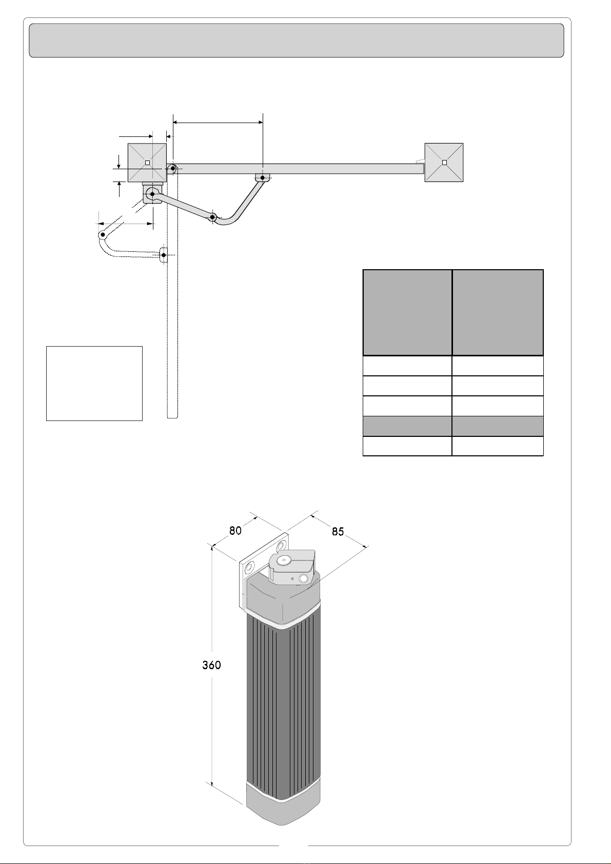
Le armoire de commande ZL150 sert àcommander les automatismes
pour portails àbattant de la série FLEX alimentés à24V c.c. avec
une puissance jusqu’à 48W, fréquence 50÷60 Hz.
Conçue et construite entièrement par CAME S.p.A., elle est conforme
aux normes NFP 25-362 en vigueur. Boîtier en ABS avec degréde
protection IP54, équipéd’une prise pour le recyclage de l’air.
Le circuit doit être alimentée avec une tension de 230V (c.a.) aux
bornes L1-L2 et doit être protégée àl’entrée par fusible de ligne de
1,6A. Les dispositifs de commande sont àbasse tension et sont
protégés par un fusible de 1,6A, tandis que le motoréducteur et la
serrure électrique sont protégés par un fusible de 5A.
La puissance totale des accessoires (24V) ne doit pas dépasser 40W.
Sécurité
Il est possible de brancher des photocellules et de les programmer
pour:
-
Réouverture
en phase de fermeture (2-C1), les cellules
photoélectriques provoquent l'inversion de marche jusqu'àl'ouverture
complète si elles relèvent un obstacle durant la phase de fermeture
du portail;
-
Réfermeture
en phase de ouverture (2-CX, dip 8OFF-10OFF), les
cellules photoélectriques provoquent l'inversion de marche jusqu'àla
fermeture complète si elles relèvent un obstacle durant la phase
d'ouverture du portail;
-
Stop partiel
, arrêt du portail, si en mouvement, et conséquente
programmation pour la fermeture automatique (2-CX, dip 8OFF-
10ON);
-
Stop total
(1-2), arrêt du portail et désactivation d’un éventuel cycle
de fermeture automatique; pour activer de nouveau le mouvement, il
faut agir sur les boutons-poussoirs ou sur la radiocommande;
Remarque
: Le voyant de signalisation qui clignote indique qu'un
contact de sécuriténormalment fermé(2-C1, 2-CX, 1-2) s'ouvre.
Accessoires en option
-
Lampe témoin portail ouvert (3W)
. Lampe qui signale la position
d’ouverture du portail et s’éteint quand le portail est en position de
fermeture. Elle est branchée sur les bornes 10-5.
-
Serrure électrique
(2-S);
-Carte LB54
. Elle alimente les motoréducteurs àl’aide de batteries
en cas de coupure de courant. Elle recharge également les batteries
quand le courant est rétabli.
Autres fonctions
-
Fermeture automatique.
Le temporisateur de fermeture automatique
est autoalimentéàla fin du temps de la course en ouverture. Le
temps réglable est programmé, cependant, il est subordonnéà
l’intervention d’éventuels accessoires de sécuritéet il est exclu après
une intervention de “stop”ou en cas de coupure de courant;
-
Détection de présence d'obstacle.
Quand le moteur est arrêté
(portail fermé, ouvert ou semi-ouvert, cette position est obtenue avec
une commande de stop total), annule toute fonction de l’émetteur ou
du bouton-poussoir en cas d’obstacle détectépar les dispositifs de
sécurité(ex. Photocellules) ;
-
Coup de bélier.
Les vantaux appuient contre la butée de fermeture
pendant une seconde àchaque commande d’ouverture en facilitant
l’opération de déclenchement de la serrure électrique branchée aux
bornes 2-S.
Il n’est activéqu’à la fin du temps de travail et si les vantaux sont
fermés ou àla 1emanœuvre après avoir coupéle courant de
l’installation;
-
Fonction “homme mort”
. Fonctionnement du portail en maintenant
appuyéle bouton-poussoir (exclut la fonction de la radiocommande);
-
Ouverture partielle
, ouverture de la porte du second moteur, réglée
àl’aide du compensateur TR2M; elle est activée en se branchant aux
bornes 2-3P;
-
Prè-clignotement
de 5 secondes en ouverture comme en fermeture
de la porte;
- T
ype de commande:
-ouverte-stop-fermée-stop pour bouton-poussoir et émetteur radio;
-ouverture - fermeture - inversion pour bouton-poussoir et émetteur
radio;
-seulement ouverture pour émetteur radio.
Réglages
- Temps de fermeture automatique;
- Temps d’ouverture partielle et retard en fermeture du moteur M2;
- Temps de fonctionnement;
Beschreibung
Die Schalttafel ZL150 eignet sich zur Steuerung von
Automatiksystemen für Flügeltore der Serie FLEX mit einer
Versorgungsspannung von 24V DC, einer Leistung von max. 48 W
und einer Frequenz von 50-60 Hz. Entwurf und Konstruktion sind von
der CAME S.p.A.; sie entspricht den geltenden Richtlinien UNI 8612.
Der Kasten ist in ABS, Schutzgrad IP54 mit Anschlußfür die
Luftrückführung.
Die Versorgung des Stromkreises erfolgt mit 230V-Sapnnung
(Wechselstrom) über die Klemmen L1-L2 und ist am Eintritt durch
1,6A-Sicherungen geschützt. Die Befehlsgeräte funktionieren mit
Niedrigspannung und sind durch eine 1,6A Sicherung geschützt. Der
Getriebemotor und das Elektroschloßdagegen sind durch eine 5A
Sicherung geschützt.
Die Gesamtleistung des Zubehörs (24V) darf 40W nicht
überschreiten.
Sicherheitsvorrichtungen
Die Lichtschranken können für folgende Funktionen angeschlossen
bzw. vorbereitet werden:
-
Wiederöffnen
beim Schließen (2-C1), die Lichtschranken ermitteln
ein Hindernis während des Schließens vom Tor und lösen die Umkehr
der Laufrichtung vom Tor aus, bis dieses wieder vollständig geöffnet
ist;
-
Wiederschließen
beim Öffnen (2-CX, Dip-Schalter 8OFF-10OFF),
die Lichtschranken ermitteln ein Hindernis während des Öffnen vom
und lösen die Umkehr der Laufrichtung vom Tor aus, bis dieses
wieder vollständig geschlossen ist;
- T
eilstop
, Stillstand des Tores während des Torlaufs, mit
darauffolgender automatischer Torschließung (2-CX, Dip Schalter
8OFF-10ON);
-
Totalstop
(1-2), sofortiger Stillstand des Tores mit Ausschluß
eventueller Schließautomatik: Fortsetzung des Torlaufs über
Drucktaster- bzw. Funksendersteuerung;
Hinweis
: Wenn sich ein normalerweise geschlossener (NC)
Sicherheitskontakt (2-C1, 2-CX, 1-2) öffnet, wird dies durch Blinken
der Kontrolleuchte angezeigt.
Extrazubehör
- Kontrolllampe Tor offen (3W)
. Zeigt an, daßdas Tor offen ist und
geht aus, wenn das Tor wieder geschlossen ist. Wird an die Klemmen
10-5 angeschlossen.
-
Elektroschloß
(2-S);
-Karte LB54
. Versorgt die Getriebemotoren bei Stromausfall mithilfe
von Batterien. Sobald der Strom wieder da ist, werden die
Notbatterien automatisch aufgeladen.
Andere Wahlfunktionen
-
Schließautomatik
. Der Schließautomatik-Zeischalter speist sich
beim Öffnen am Ende der Torlaufzeit selbst . Die voreingestellte Zeit
ist auf jeden Fall immer dem Eingriff eventueller
Sicherheitsvorrichtungen untergeordnet und schließt sich nach einem
“Stop”-Eingriff bzw. bei Stromausfall selbst aus;
-
Ermittlung eventuell vorhandener Hindernisse
. Bei stillstehendem
Motor (Tor geschlossen, geöffnet oder durch eine Totalstop-Steuerung
halb geöffnet) wird bei durch die Sicherheitsvorrichtungen (z.B.:
Lichtschranken) erfaßtem Hindernis jede Sender- oder
Drucktasterfunktion annulliert;
-
Widderstoß:
Jedesmal, wenn der Befehl zum Öffnen gegeben wird,
drücken die Torflügel eine Sekunde lang gegen den Endanschlag vom
Schließen, so daßdie Entriegelung vom Elektroschloßvereinfacht
wird, das an die Klemmen 2-S angeschlossen ist.
Der Widderstoßist nur bei geschlossenen Torflügeln aktiviert, bei
Arbeitsende oder beim ersten Manöver nach dem Einschalten vom
Strom;
-
Funktion “Bedienung vom Steuerpult”
. Torbetrieb durch Druck-
tasterbetätigung (Funkfernsteuerung ausgeschlossen);
-
Teilweises Öffnen
, Öffnen vom Torflügel des zweiten Motors, das
über den Timer TRM2, geregelt wird. Diese Funktion wird durch den
Anschlußan die Klemmen 2-3P aktiviert;
-
Vorblinken
. Das Licht blinkt sowohl vor dem Öffnen als auch vor
dem Schließen zunächst 5 Sekunden lang;
-
Steuerart
:
-Öffnen-Stop-Schließen-Stop für Drucktaster- und Funksendersteur.;
-Öffnen - Schließen - Torlaufumsteuerung für Drucktaster- und
Funksendersteuerart;
-nur Öffnen für Funksendersteuerart.
Einstellungen
- Zeiteinstellung Schließautomatik;
- Zeit für das teilweise Öffnen und Verzögerung vom Motor 2 beim
Schließen;
- Laufzeit.

9
CUADRO DE MANDO ZL150 - Caracteisticas generales
ESPANOLESPANOL
ESPANOLESPANOL
ESPANOL
Le prestazioni da noi indicate sono valide solo se il montaggio
èstato eseguito correttamente, secondo le nostre indicazioni
tecniche.
The performance listed in the specifications can only be obtained if
the unit has been correctly assembled and installed according to our
instructions.
Le performances: les performances indiquées sont valables
uniquement si le montage a étéeffectuécorrectment, selon nos
instructions techniques.
Leistungen: Die werkseits angegebenen Leistungen werden nur bei
fachgerechter Montage gemäß unserer technischen Angaben
gewährleistet.
Las prestaciones que aquíse indican valen sólo si se ha
realizado correctamente el montaje, con arreglo a nuestras
instrucciones técnicas.
ATTENZIONE :
prima di intervenire all'interno dell'apparecchiatura, togliere la
tensione.
WARNING:
always disconnect the unit from the power supply before carrying
out maintenance or repairs.
ATTENTION:
Avant d’intervenir àl’interieur de l’appareillage, couper le
courant.
ACHTUNG:
Vor Eingriffen im Innern des Gerätes immer die Stromzufuhr
unterbrechen!
CUIDADO:
antes de intervenir en el interior del equipo, cortar la tensión.
NOTE |
NOTE
| NOTE |
ANMERKUNG
| NOTA
¡Atención! Antes de actuar dentro del aparato, quitar la
tensión de línea.
197
290
264
174
110
MISURE D'INGOMBRO |
OVERALL DIMENSIONS
|MESURES D'ENCOMBREMENT |
ABMESSUNGEN
|MEDIDAS
Descripción
El cuadro de mando ZL150 sirve para accionar las automatizaciones
para cancelas de batiente de la serie FLEX alimentadas a 24V c.c.
con potencia de hasta 48W, frecuencia 50÷60 Hz.
Diseñado y fabricado completamente por CAME S.p.A., responde a
las normas UNI 8612 vigentes. Caja de ABS con grado de protección
IP54, con toma para recirculación de aire.
El circuito se alimento con tensión a 230V (c.a.) en los bornes L1-L2
y estáprotegida en entrada con fusible de línea de 1,6A. Los
dispositivos de mando son de baja tensión y están protegidos con
fusible de 1,6A, mientras que el motorreductor y la electrocerradura
están protegidos con fusible de 5A.
La potencia total de los accesorios (24V) no debe superar los 40W.
Seguridad
Las fotocélulas pueden estar conectadas y predispuestas para:
-
Reapertura
en la fase de cierre (2-C1), las fotocélulas detectan un
obstáculo durante el cierre de la puerta, provocando la inversión de
marcha hasta la apertura completa;
-
Recierre
en la fase de apertura (2-CX, dip 8OFF-10OFF), las
fotocélulas detectan un obstáculo durante la apertura de la puerta,
provocando la inversión de marcha hasta el cierre completo;
-
Parada parcial,
parada de la puerta si se encuentra en movimiento
con la consiguiente predisposición al cierre automático (2-CX, dip
8OFF-10ON);
-
Parada total
(1-2), parada de la puerta excluyendo el posible ciclo
de cierre automático; para reactivar el movimiento es preciso actuar
en el teclado o en el mando a distancia;
Nota
: La apertura de un contacto de seguridad normalmente cerrado
(2-C1, 2-CX, 1-2) es señalada por medio del destello del LED de
señalización.
Accesorios opcionales
-
Lámpara indicadora cancela abierta (3W)
. Lámpara que señala la
posición de apertura de la cancela, se apaga cuando la cancela está
en posición de cierre. Conectada a los bornes 10-5.
-
Cerradura eléctrica
(2-S);
- Tarjeta LB54
. Alimenta los motorreductores con las baterías si falta
energía eléctrica. Al restablecer la línea, también recarga las bate-
rías.
Otras funciónes
-
Cierre automático
. El temporizador de cierre automático se autoali-
menta en fin-de-tiempo carrera en fase de apertura. El tiempo
prefijado regulable, sin embargo, estásubordinado a la intervención
de posibles accesorios de seguridad y se excluye después de una
intervención de parada o en caso de falta de energía eléctrica;
-
Detección de presencia obstáculo.
Con el motor parado (puerta
cerrada, abierta o en posición semi-abierta obtenida a través de un
comando de stop total), anula cualquier función del transmisor o del
botón en caso de obstáculo detectado por los dispositivos de
seguridad (por ejemplo: fotocélulas);
-
Golpe de ariete.
Cada vez que se da un mando de apertura, las
hojas presionan en el tope de cierre por un segundo, facilitando la
operación de desenganche de la cerradura eléctrica conectada en los
bornes 2-S.
Estáactivo sólo si las hojas están cerradas y al final del tiempo de
funcionamiento, o bien en la 1amaniobra tras haber conectado la
tensión a la instalación;
-
Función a "hombre presente"
. Funcionamiento de la puerta
manteniendo pulsada la tecla (excluye la función del mando a
distancia);
-
Apertura parcial
, apertura de la hoja del segundo motor, regulada
mediante trimmer TR2M; se activa mediante lo bornes 2-3P;
-
Preintermitencia
de 5 segundos tanto en el momento de apertura
como de cierre de la puerta;
-
Tipo de mando;
-apertura-parada-cierre-parada para tecla y transmisor de radio;
-apertura-cierre-inversión para tecla y transmisor de radio;
-sólo apertura para transmisor de radio.
Regulaciones
- Tiempo cierre automático;
- Tiempo de apertura parcial y retardo en el cierre del motor M2;
- Tiempo trabajo.

10
QUADRO COMANDO -
CONTROL PANEL
-ARMOIRE DE COMMANDE -
SCHALTTAFEL
- CUADRO DE MANDO
PRINCIPALES COMPONENTES
1Caja de bornes las conexiónes
2 Fusible de línea 1.6A
3 Fusible para central 1.6A
4Indicador luminoso
5 Teclas memorización códigos
6Trimmer de regulación tiempo trabajo
7Trimmer de regulación tiempo cierre automático
8Trimmer de regulación retraso cierre 2°motor y aper-
tura parcial
9Selector de funciones con 10 dip (vedas pag.12)
10 Conexión tarjeta radiofrecuencia
11 Fusible motor/electrocerradura 5A
E
HAUPTKOMPONENTEN
1AnschlußKlemmenleiste
2 Hauptsicherung 1.6A
3 Schaltkastensicherung 1.6A
4LED Kontrolleuchte zur Anzeige
5 Code-Speichertasten
6Trimmer zur Einstellung Laufzeit
7Trimmer zur Einstellung der Schließautomatik
8Trimmerzur EinstellungSchließverzögerungMotor
2 und Teilweises Öffnung
9Wählschalter für Funktionen mit 10 Dip (sehen
S.12)
10 SteckanschlußFunkfrequenze-Platine
11 Elektroschloß/Motorsicherung 5A
D
PRINCIPAUX COMPOSANTS
1Plaque àbornes de connexion
2 Fusible de ligne 1.6A
3 Fusible boîtier 1.6A
4LED de signalisation
5 Boutons-poussoir mémorisation code radio
6Trimmer de réglage temps de fonctionnement
7Trimmer de réglage fermeture automatique
8Trimmer de réglage retard fermeture moteur 2àet
ouverture partielle
9Selecteur de fonctions à10 interrupteurs àpositions
multiples (voir pag.11)
10 Branchement carte radiofréquence
11 Fusible moteur/serrure électrique 5A
F
MAIN COMPONENTES
1Terminal block for external conections
2 1.6A line fuse
3 1.6A central control unit fuse
4Signal LED
5 Radio-code save buttons
6Trimmer for adjustment operating time
7Trimmer for adjustment automatic closing
8Trimmer for adjustment delay on closing cycle
motor n°2 and partial opening
910-dip function switch (see p.11)
10 Radiofrequency board socket
11 5A motor/electric lock fuse
GB
COMPONENTI PRINCIPALI
1Morsettiere di collegamento
2 Fusibile di linea 1.6A
3 Fusibile centralina 1.6A
4LED di segnalazione
5Pulsanti memorizzazione codice radio
6Trimmer di regolazione tempo lavoro
7Trimmer di regolazione tempo in chiusura automa-
tica
8Trimmer di regolazione ritardo in chiusura 2°moto-
re e apertura parziale
9Selettore funzioni a 10 dip (vedi pag.11)
10 Innesto scheda radiofrequenza
11 Fusibile motore/elettroserratura 5A
I
AF
ZL150
QUADROCOMANDO
T.L. T.C.A. AP.PARZ.
2
1 345678910
ON
FUSIBILE
LINEA 5A
FUSIBILE
CENTR. 1.6A
01524 20L1T L2T
FUSIBILE
MOTORE/SERR.5A
33
33
3
22
22
211
11
1
55
55
566
66
677
77
788
88
899
99
9
1010
1010
10
44
44
4
1111
1111
11

11
AF
ZL150
QUADROCOMANDO
T.L. T.C.A. AP.PARZ.
2
1 3 4567 8910
ON
FUSIBILE
LINEA5A
FUSIBILE
CENTR.3.15A
L1T L2T 01524 20
DIP-SWITCH 10 VIE
10-WAY DIP-SWITCH
DIP-SWITCH 10 VOIES
ZEHNWEG-DIP-SWITCH
DIP-SWITCH 10 VÍAS
1 ON Chiusura automatica attivata; (1OFF-disattivata)
2 ON "Apre-stop-chiude-stop" con pulsante (2-7) e radio-
comando (scheda AF inserita) attivata;
2 OFF "Apre-chiude" con pulsante (2-7) e radiocomando
(scheda AF inserita) attivata;
3 ON "Solo apertura" con radiocomando (scheda AF
inserita) attivata; (3OFF-disattivata)
4 ON Prelampeggio in apertura e chiusura attivato; (4OFF-
disat.)
5 ON Rilevazione presenza ostacolo attivato; (5OFFdis.)
6 OFF "Uomo presente" (esclude il funzionamento del
radiocomando) disattivata; (6ON - attivata)
7 ON Colpo d'ariete attivato; (per facilitare lo sgancio della
serratura) 7OFF-disattivato
8 OFF - 10OFF Funzione di richiusura in fase di apertura
(collegare il dispositivo di sicurezza sui morsetti 2-CX)
attivato;
8 OFF - 10ON Funzione di stop parziale (collegare il
dispositivo di sicurezza sui morsetti 2-CX) attivato;
(se non vengono utilizzati i dispositivi su 2-CX, posizionare il
dip 8 in ON)
9 OFF Funzione di riapertura in fase di chiusura attivato; con
dispositivo di sicurezza collegato ai morsetti 2-C1, (se
non viene utilizzato il dispositivo, selezionare il dip in
ON)
2
134567
8910
O
N
ONON
ONON
ON
OFFOFF
OFFOFF
OFF
ITALIANOITALIANO
ITALIANOITALIANO
ITALIANO
SELEZIONI FUNZIONI -
SELECTION OF FUNCTIONS
-SÉLECTION FONCTIONS
FUNKTIONSWAHL
- SELECCIÓN DE LAS FUNCIONES
1 ON Automatic closure enabled; (1OFF-disabled)
2 ON "Open-stop-close-stop" with button (2-7) and radio
control (AF board inserted) enabled;
2 OFF "Open-close" with button (2-7) and radio control (AF
board inserted) enabled;
3 ON "Only opening" with radio control (AF board inserted)
enabled; (3OFF-disabled)
4 ON Pre-flashing (opening and closing) enabled; (4OFF-
disabled)
5 ON Obstacle detection device enabled; (5OFF -
disabled)
6 OFF "Operator present" (radio remote control is
deactivated when function is selected) disabled;
(6ON-enabled)
7 ON Hammer movement operation enabled; (this function
helps unlock the electric lock) 7OFF-disabled
8OFF - 10OFFRe-closure during opening (connect the safety
device on terminals (2-CX) enabled;
8OFF - 10ON Partial stop (connect the safety device on
terminals (2-CX) enabled;
(if the devices on the 2-CX terminals are not used, set Dip 8 in
ON)
9 OFF Re-opening in closing phase (connect the safety
device on terminals 2-C1) enabled; if not used, set
the dip-switch to ON.
1 ON Fermeture automatique activé; (1OFF-éteinte)
2 ON "Ouvre-stop-ferme-stop" avec bouton (2-7) et
commande-radio (carte AF insérée) activé;
2 OFF "Ouvre-ferme" avec bouton (2-7) et commande-radio
(carte AF insérée) activé;
3 ON "Soulement ouverture" avec commande-radio (carte
AF insérée) activé; (3OFF-éteinte)
4 ON Preclignotement pandant la phase d'ouverture et de
fermeture activé; (4OFF-éteinte.)
5 ON Dispositif de détection d'obstacle activé; (5OFF
éteinte)
6 OFF Fonction avec "homme mort" (exclut la fonction
radiocommande) éteinte; (6ON - activé)
7 ON Fonction coup de bélier activé; (pour faciliter le
déblocage de la serrure) 7OFF-éteinte
8OFF - 10OFF Réfermeture en phase d'ouverture (relier le
dispositif de sécurite aux bornes 2-CX) activé;
8OFF - 10ON Stop partiel (relier le dispositif de sécurite
aux bornes 2-CX) activé;
(si le dispositif sur 2-CX ne sont pas utilisés, positionner le dip
8 sur ON)
9 OFF Réouverture en phase de fermeture activé; relier le
dispositif de sécuritèaux bornes 2-C1; s'il n'est pas
utilisé, positionner l'interrupteur àpositions multiples
sur ON.
ENGLISHENGLISH
ENGLISHENGLISH
ENGLISH FRANÇAISFRANÇAIS
FRANÇAISFRANÇAIS
FRANÇAIS

12
DEUTSCHDEUTSCH
DEUTSCHDEUTSCH
DEUTSCH
1 ON Schließautomatik zugeschaltet; (1OFF -
ausgeschlossen)
2 ON "Öffnen-Stop-Schließen-Stop" mit Druckknopf (2-7)
und Fernsteuerung (Karte AF eingesteckt)
zugeschaltet;
2 OFF "Öffnen-Schließen" mit Druckknopf (2-7) und
Fernsteuerung (Karte AF eingesteckt) zugeschaltet;
3 ON "Nur Öffnen" mit Fernsteuerung (Karte AF eingesteckt)
zugeschaltet; (3 OFF -ausgeschlossen)
4 ON Vorblinken beim Öffnen und Schließen zugeschaltet;
(4OFF -ausgeschlossen)
5 ON Hindemisaufnahme zugeschaltet; (5OFF -
ausgeschlossen)
6 OFF Bedienung vom "Steuerpult" (bei Wahl dieser
Betriebsart wird die Funkfernsteuerung ausgesch.)
ausgeschlossen; (6ON-zug.)
7 ON Widderstoßzugeschaltet; (durch diese Funktion wird
das Auslösen des Elektroschlosses erleichtert) 7OFF-
aus.)
8OFF - 10OFF Erneutes Schließen in der Öffnungsphase
(schließen Sie die Sicherheitsvorrichtung an die
Klemmen 2-CX an) zugeschaltet;
8OFF - 10ON Teilstop (schließen Sie die
Sicherheitsvorrichtung an die Klemmen 2-CX an)
zugeschaltet;
(Wenn die Sicherungen nicht an die Klemmen 2-CX
angeschlossen werden, die Dip 8 auf ON stellen)
9 OFF Wiederöffnen beim Schließen zugeschaltet;
(schließen Sie die Sicherheitsvorrichtung an die
Klemmen 2-C1 an); falls nicht verwendet, schalten Sie
den Dip auf ON)
ESPAÑOLESPAÑOL
ESPAÑOLESPAÑOL
ESPAÑOL
1 ON Cierre automático activado; (1OFF-desactivado)
2 ON "Abrir-parada-cerrar-parada" con botón (2-7) y
radiocontrol (tarjeta AF conectada) activado;
2 OFF "Abrir-cerrar" con botón (2-7) y radiocontrol (tarjeta AF
conectada) activado;
3 ON "Solo apertura" con radiocontrol (tarjeta AF
conectada) activado; (3OFF-desactivado)
4 ON Pre-intermitencia en la fase de apertura y cierre
activado; (4OFF-desactivado)
5 ON Detección del obstáculo activado; (5OFFdesacti.)
6 OFF "Hombre presente" (escluye la función del mando de
radio) desactivado; (6ON - activado)
7 ON Golpe de ariete activado; (esta función sirve para
agilizar desenganche de la electrocerradura) 7OFF-
desacti.)
8OFF - 10OFF Recierre durante la apertura (conecte el
dispositivo de seguridad a los bornes 2-CX) activado;
8OFF - 10ON Parada parcial (conecte el dispositivo de
seguridad a los bornes 2-CX) activado;
(si no utiliza los dispositivos en 2-CX, coloque el dip 8 en ON)
9 OFF Reapertura en la fase de cierre (conecte el dispositivo
de seguridad a los bornes 2-C1) activado; si no se
utiliza, poner el dip en ON
REGOLAZIONI -
ADJUSTMENTS
-RÉGLAGES -
EINSTELLUNGEN
- REGULACIONES
AF
ZL150
QUADROCOMANDO
T.L. T.C.A. AP.PARZ.
2
1 345678910
ON
FUSIBILE
LINEA5A
FUSIBILE
CENTR.1.6A
01524 20L1T L2T
FUSIBILE
MOTORE/SERR.5A
ITALIANOITALIANO
ITALIANOITALIANO
ITALIANO
FRANÇAISFRANÇAIS
FRANÇAISFRANÇAIS
FRANÇAIS
Trimmer T.L.
= Regolazione tempo di lavoro da un minimo di
15”a un massimo di 120”.
Trimmer T.C.A.
= Regolazione tempo di chiusura automatica
da un minimo di 1”a un massimo di 120”.
Trimmer TR2M
= Regolazione ritardo in chiusura 2°motore
(min. 0”, max. 15”) e contemporaneamente apertura parziale
(min. 0”, max. 30”).
ENGLISHENGLISH
ENGLISHENGLISH
ENGLISH
ESPAÑOLESPAÑOL
ESPAÑOLESPAÑOL
ESPAÑOL
DEUTSCHDEUTSCH
DEUTSCHDEUTSCH
DEUTSCH
REGULACIÓN TRIMMERS
EINTELLUNG TRIMMERS
RÉGLAGE TRIMMERS
TRIMME RS A DJUS TME NT
REGOLAZIONE TRIMMERS
T.L. T.C.A. TR2M.
Trimmer T.L.
= Adjusts of operating time from a minimum of
15”to a maximum of 120”.
Trimmer T.C.A.
= Adjusts automatic closing time from a
minimum of 1”to a maximum of 120”.
Trimmer TR2M
= Adjustment delay during closure of 2nd
motor (min. 0”, max. 15”) and simultaneously partial opening
time (min. 0”, max. 30”).
Trimmer T.L.
= Réglage du temps de fonctionnement d'un
minimum de 15”àun maximun de 120”.
Trimmer T.C.A.
= Réglage du temps de fermeture
automatique d'un minimum de 1”àun maximun de 120”.
Trimmer TR2M
= Réglage retard en fermeture 2°moteur
(min. 0”, max. 15”) et en même temps ouverture partielle
(min. 0”, max. 30”).
Trimmer T.L.
= Laufzeit mit mindestens 15”und höchstens
120 “eingestellt werden kann.
Trimmer T.C.A.
= Timer, auf dem die Verzögerung für das
automatische Schlißen mit mindestens 1”und höchstens
120”eingestellt werden kann.
Trimmer TR2M
= Einstellung der Verzögerungszeit vom 2.
Motor beim Schließen (min. 0”, max. 15”) und gleichzeitig
vom Teilöffnen (min. 0”, max. 30”).
Trimmer T.L.
= Regulación tiempo de trabajo, desde un
mínimo de 15”hasta un máximo de 120”.
Trimmer T.C.A.
= Regulación tiempo de cierre automático,
desde un mínimo de 1”hasta un máximo de 120”.
Trimmer TR2M
= Regulación del retardo durante el cierre
del 2°motor (min. 0”, máx. 15”) y contemporáneamente
apertura parcial (min. 0”, máx. 30”).

13
COLLEGAMENTI ELETTRICI -
ELECTRICAL CONNECTIONS -
BRANCHEMENTS ÉLECTRIQUES
ELEKRISCHE ANSCHLÜSSE -
CONEXIONES ELÉCTRICAS
1010
1010
10
55
55
5
1010
1010
10
EE
EE
E
M1M1
M1M1
M1
N1N1
N1N1
N1
L1L1
L1L1
L1
L2L2
L2L2
L2
Alimentazione quadro comando - 230V (a.c.)
Power supply for control unit - 230V (a.c.)
Alimentation armoire de commande - 230V (c.a.)
Stromversorgung Steuergerät - 230V (Wechselstrom)
Alimentación cuadro de mando - 230V (a.c.)
Collegamento 1 Motore (ritardato in apertura)
Connection for 1 motor (delayed in opening)
Connection du moteur 1 (retardéen ouverture)
AuschlußMotor 1 (verzögertes Ansteuern beim Öffnen)
Conexionado 1 motor (redardo en apertura)
Collegamento 2 Motore (ritardato in chiusura)
Connection for 2 motor (delayed in closing)
Connection du moteur 2 (retardéen fermeture)
AuschlußMotor 2 (verzögertes Ansteuern beim Schließen)
Conexionado 2 motor (redardo en cierre)
Uscita (24V a.c. - 25W max.) in movimento (es. lampeggiatore)
(24V a.c. - 25W max.) output in motion (e.g. flashing light)
Sortie (24V c.a. - 25W max.) en mouvement (ex. branchement clignotant)
Ausgang (24V Wechselstrom - 25W max.) in Bewegung (z.B. Blinker-Anschluß)
Salida de (24V a.c. - 25W max.) en movimiento (p.ej. conexión lámpara
intermitente)
Lampada spia (24V a.c. - 3W max.) "cancello aperto"
(24V a.c. - 3W max.) "gate-opened" signal lamp
Lampe-témoin (24V a.c. - 3W max.) "portail ouverture"
Signallampe (24V a.c. - 3W max.) "Tor Öffnen"
Lampara indicadora (24V a.c. - 3W max.) "puerta abierta"
Uscita 24V (a.c.) alimentazione accessori (max 40W)
24V (a.c.) output power supply to accessories (max. 40W)
Sortie 24V (c.a.) alimentation accessoires (max 40W)
Ausgang 24V (Wechselstrom) stromversorgung Zubehör (max 40W)
Salida 24V (a.c.) alimentación accesorios (max 40W)
Collegamento elettroserratura (12V-15W max.)
Connection for electrically-actuated lock: 12V-15W max.
Connexion serrure électrique (12V-15W max.)
AnschlußElektroschloß(12V-15W max.)
Conexión electrocerradura (12V-15W max.)
Pulsante di stop (N.C.)
Stop button (N.C.)
Bouton-poussoir de stop (N.F.)
Stop-Taste (Ruhekontakt)
Tecla de parada (N.C.)
Nel caso si utilizzi
un solo motore,
collegarlo in uscita
M2 e N2.
If only one reduction
gear is used, connect
the motor to output M2
and N2.
Si on n’utilise qu’un
seul moteur, brancher
le moteur àla sortie
M2 et N2.
Wenn nur ein Motor
verwendet wird, Den
Motor an den Ausgang
M2 und N2.
Si se usa un sólo
motor, conecte el
motor a la salida M2
y N2.
L1 L2 M1 N1 M2 N2 E 10 11 S 1 2 3 3P 4 5 7 2 C1CX B1B2
M2M2
M2M2
M2
N2N2
N2N2
N2
11
11
1
22
22
2
1010
1010
10
1111
1111
11
22
22
2
SS
SS
S
S12
3
1-2
se non usato
if not used
si non utilisée
falls nicht verwendet
si no se usa

14
Pulsante apre (N.O.)
Open button (N.O.)
Bouton-poussoir d'ouverture (N.O.)
Taste Öffnen (Arbeitskontakt)
Tecla de apertura (N.O.)
Pulsante (N.O.) per apertura parziale (apertura del 2°motore)
Pushbutton (N. O.) partial opening (opens to motor no. 2)
Bouton-poussoir (N.O.) pour ouverture partielle (ouverture du 2°moteur)
Drucktaster (Arbeitskontakt) für Teilweises Öffnen (Öffnung eines einzigen Torflügels über
Motor 2)
Tecla (N.O.) para apertura parcial (apertura del 2°motor)
Pulsante chiude (N.O.)
(N.O.) Pushbutton-close
Bouton-poussoir fermeture (N.O.)
Taste Schließen (Arbeitskontakt)
Pulsador de cierre (N.O.)
Contatto (N.C.) di riapertura in fase di chiusura
Contact (N.C.) for re-opening during closing
Contact (N.F.) de réouverture pendant la fermeture
Ruhekontakt Wiederöffnen beim Schließen
Contacto (N.C.) para la reapertura en la fase de cierre
Collegamento radio e/o pulsante (N.O.) per comandi
(vedi dip-switch 2-3 sel.funzioni)
Contact radio and/or button for control
(see dip-switch 2-3 function selection)
Contact radio et/ou poussoir pour commande
(voir dip-switch 2-3 sel.fonction)
Funkkontakt und/oder Taste Steuerung
(siehe dip-switch 2-3 Funktionswahl)
Contacto radio y/o pulsador para mando
(vedas dip-switch 2-3 seleción función)
Uscita contatto (N.O.) Portata contatto: 5A - 24V d.c.
Contact output (N.O.) Resistive load: 5A -
24V d.c.
Sortie contact (N.O.) Portée contact: 5A - 24V c.c.
Ausgang Arbeitskontakt Stromfestigkeit: 5A - 24V Gleichstrom
Salida contacto (N.O.) Carga resistiva: 5A - 24V d.c.
Collegamento antenna
Antenna connection
Connexion antenne
Antennenanschluß
Conexión antena
Contatto (N.C.) di richiusura durante l'apertura
Contact (N.C.) for re-closing during opening
Contact (N.F.) de réfermeture pendant l'ouverture
Runekontakt Wiederschließen beim Öffnen
Contacto (N.C.) de recierre en la fase de apertura
Contatto (N.C.) stop parziale
Contact (N.C.) partial stop
Contact (N.F.) stop partiel
Runekontakt Teilstop
Contacto (N.C.) parada parcial
22
22
2
33
33
3
22
22
2
3P3P
3P3P
3P
22
22
2
44
44
4
22
22
2
C1C1
C1C1
C1
22
22
2
CXCX
CXCX
CX
B1B1
B1B1
B1
B2B2
B2B2
B2
22
22
2
77
77
7
2
1345678910O
N
2
1345678910O
N
8 OFF - 10 OFF
8 OFF - 10 ON

15
ENGLISH
PROCEDURE
A. insert an
AF card.
B. encode
transmitter/s.
C. store code in the
motherboard.
FRANCAIS
PROCEDURE
A. placer une carte
AF.
B. codifier le/s
émetteur/s.
C. mémoriser la
codification sur la
carte base.
DEUTSCH
PROZEDUR
A. Stecken Sie eine
Karte AF.
B. Codieren Sie den/
die Sender.
C. Speichern Sie die
Codierung auf der
Grundplatine.
ITALIANO
PROCEDURA
A. inserire una
scheda AF.
B. codificare il/i
trasmettitore/i.
C. memorizzare la
codifica sulla
scheda base.
ESPANOL
PROCEDIMIENTO
A. introducir una
tarjeta AF.
B. codificar el/los
transmisor/es.
C. memorizar la
codificación en la
tarjeta base.
A
INSTALLAZIONE DEL RADIOCOMANDO -
RADIO CONTROL INSTALLATION -
INSTALLATION DE LA RADIOCOMMANDE
INSTALLATION DER RADIOSTEUERUNG -
INSTALACIÓNDEL RADIOMANDO
INSERIMENTO SCHEDA AF -
AF BOARD INSERTION
- INSTALLATION DE LA CARTE AF
EINSTECKEN DER KARTE AF-
MONTAJE DE LA TARJETA AF
La schedina AF deve essere inserita
OBBLIGATORIAMENTE in assenza di
tensione.
The AF board should ALWAYS be
inserted when the power is off.
La carte AF doit OBLIGATOIREMENT
être branchée en l’absence de
tension.
Vor Einschieben der Karte die
Stromzufuhr UNBEDINGT abschalten.
La tarjeta AF se debe montar
OBLIGATORIAMENTE en caso de
falta de corriente. Frequenza / MHz
Frequenc
y
/ MHz
Frequence / MHz
Frequenz / MHz
Frecuencia / MHz
Scheda radiofrequenza
Radiofrequenc
y
board
Carte radiofréquence
Funkfrequenz-Platine
Tarjeta radiofrecuencia
Trasmettitore
Transmitter
Emetteur
Funksender
Transmisor
FM 26.995 AF130 TFM
FM 30.900 AF150 TFM
AM 26.995 AF26 TOP
AM 30.900 AF30 TOP
AM 433.92 AF43S / AF43SM TAM / TOP
AF43SR ATOMO
AF
L
150
D
ROCOMANDO
2
1 345678910
SCHEDA BASE
MOTHERBOARD
CARTE DE BASE
BASISKARTE
TARJETA BASE
SCHEDA "AF"
"AF" BOARD
CARTE "AF"
KARTE «AF»
TARJETA «AF»

16
CODIFICA TRASMETTITORI -
TRANSMITTER ENCODING
- CODIFICATION DES EMETTEURS
CODIERUNG DER SENDER -
CODIFICACIÓN TRANSMISORES
B
TOP
QUARZATI
- QUARTZ
- AU QUARTZ
- QUARTZGENAUE
- CUARZO
PROCEDURA COMUNE DI CODIFICA
T262M-T264M-T2622M
T302M-T304M-T3022M
1.segnare un codice (anche per archivio)
2.inserire jumper codifica J
3.memorizzarlo
4.disinserire jumper J
STANDARD ENCODING PROCEDURE
T262M-T264M-T2622M
T302M-T304M-T3022M
1.assign a code (also on file)
2.connect encoding jumper J
3.register code
4.disconnect jumper J
PROCEDURE COMMUNE DE CODIFICATION
T262M-T264M-T2622M
T302M-T304M-T3022M
1.taper un code (également pour les
archives)
2.placer un cavalier de codification J
3.mémoriser le code
4.enlever le cavalier J
ANLEITUNGEN ZUR CODIERUNG
T262M-T264M-T2622M
T302M-T304M-T3022M
1.Ordnen Sie einen Code zu (auch für das
Archiv).
2.Schalten Sie den Codierungs-Jumper J ein.
3.Speichern Sie den Code.
4.Schalten Sie den Jumper J wieder aus.
PROCEDIMIENTO COMÚNDE CODIFICACIÓN
T262M-T264M-T2622M
T302M-T304M-T3022M
1.marcar un código (también para el
archivo)
2.conectar un jumper codificación J
3.registrar el código
4.desconectar jumper J
P1 P2
P3 P4
P1=CH1 - P2=CH2
P3=CH3 - P4=CH4
J
T264M - T304M
La prima codifica deve essere effettuata mantenendo i jumper
posizionati per i canali 1 e 2 come da fig. A; per eventuali e succes-
sive impostazioni su canali diversi vedi fig. B
The first encoding operation must be carried out whilst keeping the
jumpers positioned for channels 1 and 2 as per fig. A; see fig. B for
any subsequent settings on different channels.
La première codification doit être effectuée en maintenant les
cavaliers en position pour les canaux 1 et 2, comme d'après la fig.
A; pour des saisies successives éventuelles sur des canaux
différents, voir fig. B
Für die erste Codierung mußder Jumper auf den Kanälen 1 und 2
positioniert bleiben (siehe Abb. A). Für eventuelle weitere oder
spätere Einstellungen auf anderen Kanälen halten Sie sich bitte an
Abb. B.
La primera codificación tiene que efectuarse manteniendo los
jumper conectados para los canales 1 y 2 como se ilustra en la fig.
A; para planteamientos posteriores en canales distintos ver la fig. B
T262M - T302M
P1 P2
J
P1=CH1
P2=CH2
fig. A fig. B
P1=CH1 - P2=CH4
P1=CH1 - P2=CH3 P1=CH3 - P2=CH2
P1=CH3 - P2=CH4
P1 P2
T2622M - T3022M
2°codice/
code/
code/
Code
/codigó
ON
OFF
P1
P2
P3=CH1
P4=CH2
J
1°codice/
code/
code/
Code
/codigó
P1=CH1
P2=CH2
J
premere in sequenza P1 o P2 per registrare il
codice; al decimo impulso un doppio suono
confermeràl'avvenuta registrazione
Press P1 or P2 in sequence in order to register
the code; at the tenth pulse, a double beep will
confirm that registration has occurred
appuyer en séquence sur P1 ou P2 pour
mémoriser le code; àla dixième impulsion, une
double sonnerie confirme que le code a été
mémorisé
Drücken Sie nacheinander P1 oder P2, um den
Code zu speichern. Nach dem zehnten Impuls
signalisiert ein doppelter Piepton, daßder Code
gespeichert worden ist.
oprimir repetidamente P1 óP2 para registrar el
código; con el décimo impulso un doble sonido
señalaráque el registro se ha efectuado.
2.
J
ON
OFF
P1
P2
codice/
codice
/codice/
codice
/codice
1.
4.
J
P1=OFF P2=ON
3.

17
vedi foglio istruzioni inserito nella confezione
see instruction sheet inside the pack
voir la notice d'instructions qui se trouve dans
l'emballage
Siehe Anleitungen, die der Packung beiliegen.
ver hoja de instrucciones adjunta en el embalaje
TAM
T132
T134
T138
T152
T154
T158
T432
T434
T438
TFM
T434M - T314M
impostare solo il
codice
set code only
ne saisir que le code
Stellen Sie nur den
Code ein.
plantear sólo el código
P1=CH1
P2=CH2
P3=CH3
P4=CH4
1 2 3 4 5 6 7 8 9 10
C
P1 P2
P3 P4
T432SA - T432S
impostare il codice sul dip-switch C e il canale su D (P1=CH1 e P2=CH2, impostazione di
default)
set the code to dip-switch C and channel to D (P1=CH1 and P2=CH2, default setting)
saisir le code sur le commutateur dip C et le canal sur D (P1=CH1 et P2=CH2, saisie de
défaut)
Stellen Sie den Code auf den Dip-Switch C und den Kanal auf D (P1=CH1 und P2=CH2;
Grundeinstellung).
plantear el código en el dip-switch C y el canal en D (P1=CH1 y P2=CH2, planteamiento
por defecto)
T432M - T312M
1 2 3 4 5 6 7 8 9 10
1 2 3 4
C
D
P1 P2
P2
CH1 CH2 CH3 CH4
P1
CH1 CH2 CH3 CH4
1 2 3 4 1 2 3 4 1 2 3 41 2 3 4
1 2 3 4 1 2 3 4 1 2 3 4 1 2 3 4
AT01 - AT02
vedi foglio istruzioni inserito nella confezione
della scheda AF43SR
see instruction sheet inside the pack of AF43SR circuit card
voir les instructions qui se trouve dans l'emballage
de la carte AF43SR
Siehe Anleitungen, die der Packung beiliegen der Platine AF43SR
ver hoja de instrucciones adjunta en el embalaje
de la tarjeta AF43SR
ATOMO
vedi istruzioni su confezione
see instructions on pack
voir instructions sur
l'emballage
Siehe Anleitungen auf der
Packung.
ver instrucciones en el
embalaje

18
MEMORIZZAZIONE CODICE -
CODE STORAGE
- MEMORISATION DU CODE
SPEICHERN VOM CODE -
MEMORIZACIÓN CÓDIGO
C
ITALIANO
Tenere premuto il
tasto "CH1" sulla
scheda base (il led di
segnalazione lampeg-
gia), con un tasto del
trasmettitore si invia il
codice, il led rimarrà
acceso a segnalare
l'avvenuta
memorizzazione (vedi
fig.1). Eseguire la
stessa procedura con
il tasto "CH2" asso-
ciandolo con un altro
tasto del trasmettitore
(fig.2).
CH1 = Canale per
comandi diretti ad una
funzione della
centralina del
motoriduttore (coman-
do "solo apre" / "apre-
chiude" oppure "apre-
stop-chiude-stop", a
seconda della selezio-
ne effetuata sui dip-
switch 2 e 3).
CH2 = Canale per
comandi diretti ad un
dispositivo accessorio
collegato su B1-B2.
N.B.: Se in seguito si
vuol cambiare codice,
basta ripetere la
sequenza descritta.
DEUTSCH
Die Taste "CH1"
gedrückt halten und
nach Aufleuchten der
Anzeige-Leuchtdiode
über den Sender-
Taster einen
Steuerimpuls
ausführen: ein kurzes
Blinken der Led zeigt
die erfolgte
Speicherung an
(Abb.1). Gehen Sie
ebenso mit Taste
"CH2" vor und ordnen
sie ihr eine andere
Taste des Senders zu
(Abb.2).
CH1 = Kanal für die
Direktsteuerung einer
Funktion des
Getriebemotor-
Schaltkastens
(Steuerung "nur
Öffnen" / "Öffnen-
Schließen" bzw.
"Öffnen-Stp-
Schließen-Stop", je
nach über Dip-Switch
2 und 3 ausgeführter
Wahl).
CH2 = Kanal für
Direktsteuerung eines
über B1-B2
angeschlossenen
Zubehörs.
HINWEIS: bei
eventuell erwünschter
Sender codeänderung
ist der beschriebene
Vorgang zu
wiederholen.
ESPANOL
Mantener oprimida la
tecla "CH1" en la
tarjeta base (el led de
señalización
parpadea), con una
tecla del transmisor se
envía el código, el led
permanece encendido
para indicar que el
almacenamendo se
ha efectuado (fig.1).
Efectuar el mismo
procedimiento con la
tecla "CH2"
asociándola a otra
tecla del transmisor
(fig.2).
CH1 = Canal para
mando directo a una
función de la central
del motorreductor
(mando "solo abre" /
"abre-cierra" o "abre-
stop-cierra-stop",
según la selección
efectuada en los dip-
switch 2 y 3).
CH2 = Canal para un
mando directo a un
dispositivo accesorio
conectado en B1-B2.
Nota: Si posterior-
mente se quisiera
cambiar el código de
los propios
transmisores, sólo hay
que repetir la
secuencia descrita.
ENGLISH
Keep the CH1 key
pressed on the base
card (the signal LED
will flash), and with a
key on the transmitter
the code is sent, the
LED will remain lit to
signal the successful
saving of the code
(figure 1).
Perform the same
procedure with the
"CH2" key,
associating it with
another transmitter
key (fig. 2).
CH1 = Channel for
direct control of one
function performed by
the control unit on the
gear motor ("open
only" / "open-close" or
"open-stop-close-
stop", depending on
the position of dip
switches 2 and 3).
CH2 = Channel for
direct control of an
accessory connected
across B1-B2.
N.B. If you wish to
change the code on
your transmitters in
the future, simply
repeat the procedure
described above.
FRANÇAIS
Appuyer sur la touche
"CH1" sur la carte de
base (le led de
signalisation clignote),
avec une touche du
emetteur on envoie le
code, le led reste
allumé pour signaler
que la mémorisation
s'est effectuèe (fig.1).
Suivre la même
procédure avec la
touche "CH2" en
l'associant avec une
autre touche du
emetteur (fig.2).
CH1 = Canal pour
obtenir la commande
directe d'une fonction
du boîtier du
motoréducteur
(commande
"uniquement ouvertu-
re" / "ouverture-
fermeture" ou
"ouverte-stop-ferme-
stop" en fonction de la
sélection effectuée sur
les dip-switchs 2 et 3).
CH2 = Canal pour
obtenir la commande
directe d'un dispositif
accessoire branché
sur B1-B2.
N.B.: Si,
successivement, on
veut changer le code
des émetteur, il suffit
de répéter la
séquence décrite ci-
dessus.
CH1
AF
T.L. T.C.A.
CH2
CH1
AF
T.L. T.C.A.
CH2
FIG. 1FIG. 1
FIG. 1FIG. 1
FIG. 1
ABB. 1ABB. 1
ABB. 1ABB. 1
ABB. 1
FIG. 2FIG. 2
FIG. 2FIG. 2
FIG. 2
ABB. 2ABB. 2
ABB. 2ABB. 2
ABB. 2
CH2CH2
CH2CH2
CH2
CH1CH1
CH1CH1
CH1
LED di segnalazione
signal LED
LED de signalisation
Anzeigeleuchtdiode
LED de señal
Scheda radiofrequenza AF
AF radiofrequency board
Carte radiofrèquence AF
Funkfrequenz-Platine AF
Tarjeta radiofrecuencia AF

19
NOTE /
NOTES
/ NOTE /
HINWEIS
/ NOTA

Tutti i dati sono stati controllati con la
massima cura. Non ci assumiamo co-
munque alcuna responsabilitàper
eventuali errori od omissioni.
All data checked with the maximum care.
However, no liability is accepted for any error
or omission.
Toutes les données ont étécontrôlées
très soigneusement. Nous n’assumons
de toute façon aucune responsabilitépour
les erreurs ou omissions éventuelles.
Die Daten wurden mit höchster Sorgfalt
geprüft. Für eventuelle Fehler oder
Auslassungen übernehmen wir keine
Haftung.
Todos los datos se han controlado con
la máxima atención. No obstante no nos
responsabilizamos de los posibles
errores u omisiones.
CANCELLI AUTOMATICI
CAME LOMBARDIA S.R.L.______COLOGNO M. (MI)
(+39) 02 26708293 (+39) 02 25490288
CAME SUD S.R.L. ___________________NAPOLI
(+39) 081 752445 (+39) 081 7529109
CAME (AMERICA) L.L.C.____________MIAMI( FL)
(+1) 305 5930227 (+1) 305 5939823
CAME AUTOMATISMOS S.A__________MADRID
(+34) 091 5285009 (+34) 091 4685442
CAME BELGIUM__________________LESSINES
(+32) 068 333014 (+32) 068 338019
CAME FRANCE S.A.____NANTERRE CEDEX (PARIS)
(+33) 01 46130505 (+33) 01 46130500
CAME GMBH________KORNTAL BEI (STUTTGART)
(+49) 07 11839590 (+49) 07 118395925
CAME GMBH____________SEEFELD BEI (BERLIN)
(+49) 03 33988390 (+49) 03 339885508
CAME PL SP.ZO.O______________WARSZAWA
(+48) 022 8699933 (+48) 022 6399933
CAME UNITED KINGDOM LTD___NOTTINGHAM
(+44) 01159 387200 (+44) 01159 382694
CAME CANCELLI AUTOMATICI S.P.A.
DOSSON DI CASIER (TREVISO)
(+39) 0422 490960 (+39) 0422 490944
SISTEMA QUALITÀ
CERTIFICATO
ASSISTENZA TECNICA
NUMERO VERDE
800 295830
WEB
www.came.it
E-MAIL
Other manuals for U 8700
1
Table of contents
Other CAME Gate Opener manuals
Popular Gate Opener manuals by other brands

GDS
GDS GDS 550P Series Installation and maintenance manual

O&O
O&O ZERO14-24V Installation, use and maintenance

GATEXPERT
GATEXPERT PY300DC user manual

Platinum Access Systems
Platinum Access Systems BLSW2212 Installation instruction and owenrs manual

SOMFY
SOMFY AXOVIA MULTIPRO installation instructions

Estate Swing
Estate Swing E-S 500 instruction manual

OSCO
OSCO GSLG-A installation guide

AGA
AGA GATEMASTER 900 HD installation manual

Comunello Automation
Comunello Automation ABACUS 220 Installation and user manual

Mighty Mule
Mighty Mule 200 E-Z GATE OPENER UL325 SERIES installation manual

TOPMAQ
TOPMAQ MK1101 user manual

Roger Technology
Roger Technology BRUSHLESS B70/2DC quick start