manuals.online logo
Brands
  1. Home
  2. •
  3. Brands
  4. •
  5. Canon
  6. •
  7. All In One Printer
  8. •
  9. Canon Smart Base MP730 Service manual

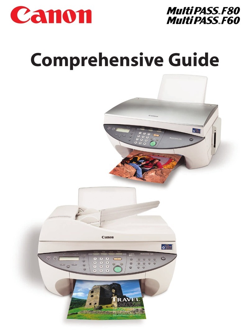
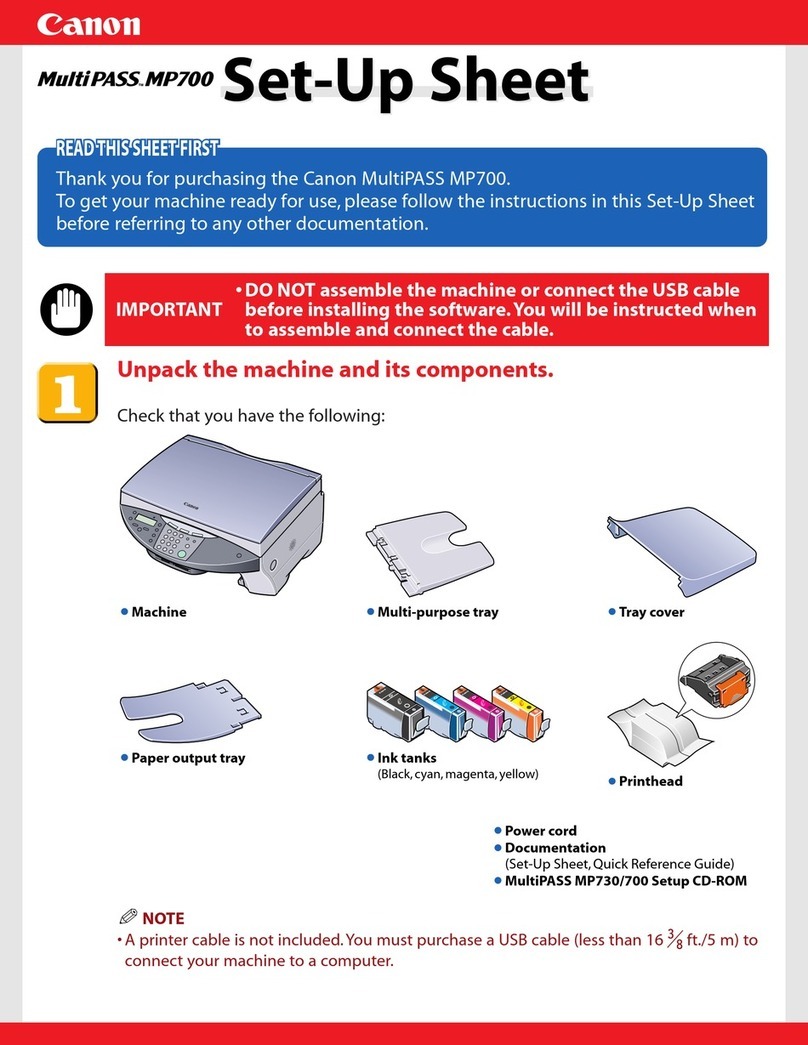
Canon Smart Base MP730 Service manual

REVISION 0
COPYRIGHT © 2003 CANON INC. CANON SmartBase MP730/MP700 MAR. 2003
CIRCUIT
DIAGRAM
HY8-80AU-000
MAR. 2003
SmartBase MP730 H12-2693 230V EU
SmartBase MP730 H12-2694 230V UK
SmartBase MP730 H12-2695 230V GER
SmartBase MP730 H12-2697 230V FRN
SmartBase MP700 H12-2703 230V EU
SmartBase MP700 H12-2704 230V UK
SmartBase MP700 H12-2705 230V E/G/F
Application
This manual has been issued by Canon Inc. for qualified persons to learn technical theory, installation, maintenance,
and repair of products. This manual covers all localities where the products are sold. For this reason, there may be
information in this manual that does not apply to your locality.
Corrections
This manual may contain technical inaccuracies or typographical errors due to improvements or changes in products.
When changes occur in applicable products or in the content of this manual, Canon will release technical information
as the need arises. In the event of major changes in the contents of this manual, Canon will issue a new editions of
this manual.
The following paragraph does not apply to any countries where such provisions are inconsistent with local law.
Trademarks
The product names and company names described in this manual are the registered trademarks of the individual
companies.
Copyright
This manual is copyrighted with all rights reserved. Under the copyright laws, this manual may not be copied,
reproduced or translated into another language, in whole or in part, without the written consent of Canon Inc.
Copyright © 2003 by Canon Inc.
CANON INC.
Consumer Imaging Products Quality Assurance Dept. 1
5-1 Hakusan 7-Chome,Toride-city, Ibaraki 302-8501, Japan
I
I. ABOUTTHIS MANUAL
This manual is divided into the following four sections and contains information
necessary for servicing the products.
1. HOW TO USE THE CIRCUIT DIAGRAM
This section describes how to read and use this manual correctly.
2. CIRCUIT DIAGRAM
This section contains information necessary for servicing the products, and
includes the circuit diagrams of the products.
3. SIGNAL ADDRESS LIST
For circuit diagrams consisting of multiple pages, the address on the other page for
each signal connecting is not included in the diagram. Therefore, refer to the signal
address list for circuit diagrams consisting of multiple pages.
4. POWER SUPPLY PARTS RATING LIST
The power supply circuit diagrams do not show the rating parts. Therefore, refer to
the power supply parts rating list for the power supply circuit diagrams.
II
II. PRODUCT NO. LIST
Thismanualdescribesthecomponentunitsofthefollowingproducts.
DRAWINGNo.
PRODUCT No.
H12-2693 H12-2703
H12-2694 H12-2704
UNIT NAME H12-2695 H12-2705
H12-2697
SPCNT BOARD ASS’Y HM1-0498 HM1-0510 HM1-0599
SENSOR BOARD ASS’Y HM1-0499 HM1-0464 HM1-0465
HM1-0503
MODULAR BOARD ASS’Y HM1-0501 HM1-0501
MULTI-CARD READER BOARD ASS’Y HM1-0502 HM1-0502 HM1-0502
NCU BOARD ASS’Y HG5-3107 HG5-3107
POWER SUPPLY UNIT HK1-0049 HK1-0049 HK1-0049
CAUTION:The numbers attachment to the technical drawings in this manual are
Design drawing numbers. In some cases the service part numbers and
Design drawing numbers do not match.
III
III. CONTENTS
PAGE TITLE DRAWING No.
11. HOW TO USETHE CIRCUIT DIAGRAM
1 1.1 Symbol
2 1.2 Index
3 1.3 Signal Address List
4 1.4 Power Supply Parts Rating List
52. CIRCUIT DIAGRAM
5 SPCNT BOARD ASS'Y
5 SPCNT BOARD ASS'Y HM1-0498-A501
6 SPCNT BOARD ASS'Y HM1-0498-A502
7 SPCNT BOARD ASS'Y HM1-0498-A503
8 SPCNT BOARD ASS'Y HM1-0498-A504
9 SPCNT BOARD ASS'Y HM1-0498-A505
10 SPCNT BOARD ASS'Y HM1-0498-A506
11 SPCNT BOARD ASS'Y HM1-0498-A507
12 SPCNT BOARD ASS'Y HM1-0498-A508
13 SPCNT BOARD ASS'Y HM1-0498-A509
14 SPCNT BOARD ASS'Y HM1-0498-A510
15 SPCNT BOARD ASS'Y HM1-0498-A511
16 SPCNT BOARD ASS'Y HM1-0498-A512
17 SPCNT BOARD ASS'Y HM1-0498-A513
18 SPCNT BOARD ASS'Y HM1-0498-A514
19 SPCNT BOARD ASS'Y HM1-0498-A515
20 SENSOR BOARD ASS'Y
20 SENSOR BOARD ASS'Y HM1-0499-A501
21 SENSOR BOARD ASS'Y HM1-0499-A502
22 SENSOR BOARD ASS'Y HM1-0499-A503
23 SENSOR BOARD ASS'Y HM1-0503-A501
24 MODULAR BOARD ASS'Y
24 MODULAR BOARD ASS'Y HM1-0501-A501
25 MULTI-CARD READER BOARD ASS'Y
25 MULTI-CARD READER BOARD ASS'Y HM1-0502-A501
26 MULTI-CARD READER BOARD ASS'Y HM1-0502-A502
27 NCU BOARD ASS'Y
27 NCU BOARD ASS'Y HG5-3107-A501
28 NCU BOARD ASS'Y HG5-3107-A502
29 POWER SUPPLY UNIT
29 POWER SUPPLY UNIT HK1-0049
30 3. SIGNAL ADDRESS LIST
30 SIGNAL ADDRESS LIST (SPCNT BOARD ASS'Y) HM1-0498
37 SIGNAL ADDRESS LIST (SENSOR BOARD ASS'Y) HM1-0499
38
SIGNAL ADDRESS LIST (MULTI-CARD READER BOARD ASS'Y)
HM1-0502
IV
39 4. POWER SUPPLY PARTS RATING LIST
39 POWER SUPPLY PARTS RATING LIST HK1-0049
1
1.HOW TO USE THE CIRCUIT DIAGRAM
1.1 Symbol
The symbols used in this circuit diagram conform to Canon standards. However,
the circuit diagram of the power supply unit, etc. which are manufactured by other
companies, use the standard symbols of those other manufacturers.
The main differences between Canon standards and those of other manufacturers
are given below.
a) Array Symbol
Figure 1 Array Symbol
b) Ground Symbol
Ground symbols are as shown below, unless specified otherwise in the diagram.
Figure 2 Ground Symbol
RESISTOR ARRAY
DIODE ARRAY
CANON STANDARD OTHER STANDARD
DIGITAL GROUND
ANALOG GROUND
RELAY GROUND
FRAME GROUND
NAME SYMBOL
2
c) JUMPERTERMINAL SYMBOL
Jumper terminal symbols are as shown below.
Figure 3 Jumper Terminal Symbol
d) UNMOUNTED PART SYMBOL
Parts marked with ### are not mounted on the PCB.
Figure 4 Unmounted part Symbol
1.2 INDEX
Each circuit diagram has an index, like the one shown here, on the lower right
hand side.
Figure 5 Index
No. : Number of modification to this manual
REMARKS : Modification content
DRAWING NAME : Name of circuit diagram
DRAWING No. : Drawing number of this diagram
MODEL NAME : Name of model corresponding to Part No.
PART No. : Service part number of relevant board in this circuit
diagram
REV. : Version number indicating revision of this diagram
No.REMARKS DRAWING NAME
DRAWING No.
REMARKS PATR No. REV.
Connected Jumper Terminal
Disconnected Jumper Terminal
###
# # #
<F. A.> <MODE>
SW330
SW330 is not mounted on the PCB.
SW340
JP328
3
1.3 SIGNAL ADDRESS LIST
The following is an example of how to read the signal address list.
Figure 6 Signal Address List
A12
A13
A13
A13
A14
A14
A14
A15
A15
A15
1
2
3
4
5
6
7
8
9
10
11
12
13
A504
A502
A503
A504
A502
A503
A504
A502
A503
A504
C-5
C-5
C-4
C-4
C-4
C-3
C-3
C-5
C-4
C-5
654321
D
C
B
A
PART No. REV.
REMARKS
DRAWING No.
DRAWING NAME
Signal Name
Drawing No.
Address
Remarks
MODEL NAME
Drawing number of the signal address list
on this page.
e.g. To see the circuit diagram of drawing
number HG1-3923, refer to the signal
address lists beginning with drawing
number HG1-3923-AA01
Row number on the signal address list.
(It has no other meaning.)
e.g. A504 refers to drawing no.
HG1-3923-A504.
Signal address is shown by the symbols at
the side of the diagrams.
e.g. Address C-5 indicates the shaded area
shown below.
e.g. For signal A13,
C-5 (address of drawing no. HG1-3923-A502)
,
C-4 (address of drawing no. HG1-3923-A503)
,
and C-4 (address of drawing no. HG1-3923-
A504) are connected.
e.g. For signal A14,
C-4 (address of drawing no. HG1-3923-A502)
,
C-3 (address of drawing no. HG1-3923-A503)
,
and C-3 (address of drawing no. HG1-3923-
A504) are connected.
PART No.
DRAWING No.
DRAWING NAME
REV.
SIGNAL ADDRESS LIST
HG1-3923-AA01
01
MODEL NAME HG1-3923FAX-B200
No.
4
1.4 POWER SUPPLY PARTS RATING LIST
The following is an example of how to read the power supply parts rating list.
Figure 7 Power Supply Parts Rating List
C001
C002
C003
C004
C005
C006
C007
C008
C009
C010
C011
C012
C013
0.22 pF/1KV
0.22 pF/250V
4700 pF/1KV
2200 pF/1KV
0.22 pF/50V
2200 pF/1KV
0.22 pF/50V
0.22 pF/1KV
0.22 pF/1KV
0.22 pF/1KV
0.22 pF/1KV
0.22 pF/1KV
0.22 pF/1KV
PART No.
DRAWING No.
DRAWING NAME
REV.
POWER SUPPLY
HH3-5244
HH3-5244 01
0.22 pF/1KV
0.22 pF/250V
4700 pF/1KV
2200 pF/1KV
0.22 pF/50V
2200 pF/1KV
0.22 pF/50V
0.22 pF/1KV
0.22 pF/1KV
0.22 pF/1KV
0.22 pF/1KV
0.22 pF/1KV
0.22 pF/1KV
Parts Ref. No.
Rating
C001
MODEL NAME
FAX-B200
Drawing number of the power supply parts
rating list on this page.
e.g. To see the circuit diagram of drawing
number HH3-5244, refer to the power
supply parts rating list of drawing
number HH3-5244.
Parts reference number in the power supply
circuit diagram.
e.g.
e.g. The capacitor of parts reference number
C001 in the power supply circuit
diagram has a rating of 0.22 pF/ 1KV.

This manual suits for next models

8

Other Canon All In One Printer manuals
Canon imageCLASS D780 Installation and maintenance instructions
Canon

Canon imageCLASS D780 Installation and maintenance instructions

Canon imageRUNNER ADVANCE 715 IF User manual

Canon

Canon imageRUNNER ADVANCE 715 IF User manual

Canon iR1022 User manual

Canon

Canon iR1022 User manual

Canon i-SENSYS MF6180dw User manual

Canon

Canon i-SENSYS MF6180dw User manual

Canon MP540 Instructions for use

Canon

Canon MP540 Instructions for use

Canon imageCLASS MF4880dw Safety guide

Canon

Canon imageCLASS MF4880dw Safety guide

Canon i-SENSYS MF4300dn User manual

Canon

Canon i-SENSYS MF4300dn User manual

Canon PIXMA MX372 User manual

Canon

Canon PIXMA MX372 User manual

Canon imageCLASS D550 Safety guide

Canon

Canon imageCLASS D550 Safety guide

Canon 1483B001 User manual

Canon

Canon 1483B001 User manual

Canon MF7280 - ImageCLASS B/W Laser Installation and operation manual

Canon

Canon MF7280 - ImageCLASS B/W Laser Installation and operation manual

Canon IMAGERUNNER 7095 PRINTER User manual

Canon

Canon IMAGERUNNER 7095 PRINTER User manual

Canon PIXMA MX860 series User manual

Canon

Canon PIXMA MX860 series User manual

Canon E4570 Setup guide

Canon

Canon E4570 Setup guide

Canon PIXMA MP500 User manual

Canon

Canon PIXMA MP500 User manual

Canon imageCLASS X MF1127C User manual

Canon

Canon imageCLASS X MF1127C User manual

Canon PIXMA MG5450 User manual

Canon

Canon PIXMA MG5450 User manual

Canon 1238iF II User manual

Canon

Canon 1238iF II User manual

Canon IR3250 Installation and maintenance instructions

Canon

Canon IR3250 Installation and maintenance instructions

Canon 3300 Series User manual

Canon

Canon 3300 Series User manual

Canon MP-C545 User manual

Canon

Canon MP-C545 User manual

Canon PIXMA MP170 User manual

Canon

Canon PIXMA MP170 User manual

Canon imageCLASS LBP151dw User manual

Canon

Canon imageCLASS LBP151dw User manual

Canon imagerunner advance 4545 Installation guide

Canon

Canon imagerunner advance 4545 Installation guide

Popular All In One Printer manuals by other brands

Samsung SCX-4623FW user manual

Samsung

Samsung SCX-4623FW user manual

Samsung SCX-3405FW Specifications

Samsung

Samsung SCX-3405FW Specifications

Konica Minolta bizhub C550 Series user guide

Konica Minolta

Konica Minolta bizhub C550 Series user guide

Brother DCP-J125 user guide

Brother

Brother DCP-J125 user guide

Xerox WORKCENTRE 5030 Specifications

Xerox

Xerox WORKCENTRE 5030 Specifications

Ricoh Aficio 1515 operating instructions

Ricoh

Ricoh Aficio 1515 operating instructions

Lexmark 544n - X Color Laser user guide

Lexmark

Lexmark 544n - X Color Laser user guide

Epson Stylus SX230 Basic operation guide

Epson

Epson Stylus SX230 Basic operation guide

Samsung SCX4521F - B/W Laser - All-in-One Service manual

Samsung

Samsung SCX4521F - B/W Laser - All-in-One Service manual

Lexmark X5495 Specifications

Lexmark

Lexmark X5495 Specifications

Redlake MASD MotionMeter Instructions for operating

Redlake MASD

Redlake MASD MotionMeter Instructions for operating

Xerox WorkCentre Pro 423E Specifications

Xerox

Xerox WorkCentre Pro 423E Specifications

Panasonic WORKIO DP-C323 operating instructions

Panasonic

Panasonic WORKIO DP-C323 operating instructions

Sharp MX-3050N quick start guide

Sharp

Sharp MX-3050N quick start guide

Savin 816 Brochure & specs

Savin

Savin 816 Brochure & specs

Xerox WorkCentre 7232 Voluntary product accessibility template

Xerox

Xerox WorkCentre 7232 Voluntary product accessibility template

Ricoh SP 313SFNW V Setup guide

Ricoh

Ricoh SP 313SFNW V Setup guide

Kyocera TASKalfa 6550ci quick guide

Kyocera

Kyocera TASKalfa 6550ci quick guide

manuals.online logo
manuals.online logoBrands
  • About & Mission
  • Contact us
  • Privacy Policy
  • Terms and Conditions

Copyright 2025 Manuals.Online. All Rights Reserved.