cantaport KCR User manual

KCR & KH installation guide
d
.
.
cantaport
y
step
6
quick
guide to
installation

2900mm
800mm
800mm
800mm
2900mm
2900mm
Centred to posts
inside to outside
1
set out
Set out for the cantaport KCR 5130, KCR 5120 ,KH 5127.Please read
the easy 6 step cantaport installation in conjunction with the manufacturers
installation manual and the engineers certification.
The cantaport posts to be set at 2900mm centred between the posts.
Height to be determined from the finish ground level. Standard height set
at 2310mm from the finished ground level.
Concrete footings
Post
Post
Concrete footings
2
bracing
Pine timber beams can be used
to support the posts near the top
and bottom of each posts. Timber
blocks can be nailed onto the beams
at the required distance to keep the
posts level and in position.
The bottom rail can be packed or
supported off the finished ground
level.(FGL)
Clamps can be fixed between the
timber beams and the posts to
provide more stability. Further bracing
can be fixed to the top beam to restrict
any movement during the concrete pour. Allow minimum 200mm of concrete around each post. Refer to the
engineerʼs certification for more details with regards to the concrete footing dimensions, soil conditions and wind rating
allowances.
Place metal rod anchor through the holes at the base of the posts. Check that the posts are level from the front and
the side. The height of one post can be lowered slightly to allow for water to fall inside the gutter to one side.
Take care during the installation of the posts. To avoid any scratches always place cardboard or rubber between the
surface of the posts and any timber bracing . The posts can be set 100mm either side from the standard set out.
New holes will need to be drilled for the bearers over the beams to accommodate the fixing points.
FGL
Clamp
Clamp
Timber beam
d
.
.
cantaport
y
step one
d
.
.
cantaport
y
step two

3
beams
The next step is to install the corner brackets into the posts. The corner brackets have
pre drilled holes to allow for the bolts to be screwed into the post & the corner bracket.
Note that the bolts should be tightened with care to avoid damage to the inside thread
of the bracket. The same process applies to the beams. The beams are then positioned
into the corner brackets. Tighten the bolts with care.
The corner brackets have plastic colour matching covers that are then positioned and
fixed into the top and side of the angle bracket. The screws provided only need to be
tightened slightly to avoid the corner covers from separating. The end of the beam has a
plastic cover that is pushed into the beam. Check that all the bolts have been securely
tightened and proceed to the next stage.
fascia
4
Refer to the manufactures installation for the correct description of the bolts
and fixing screws that are required. The cantaport unit is pre cut and pre drilled
and does not require any modification unless the posts have been
positioned outside the recommended set out positions. When undertaking
the tightening of any screw or bolt, care must be taken at all times. Aluminium
is a soft metal and does not require a lot of force to tighten the fixings.
The next stage is to install the surround of the roof perimeter. The small stainless steel brackets are
fixed to the end of the both sides to the beams. The fascia is then placed against the brackets and
fixed into place. The same applies to the gutter. The pre drilled holes to the gutter and fascia
should match up to the holes on the stainless steel brackets. No new holes are required unless the
posts have been installed outside the standard set out .
The plastic corner fittings are placed into the cavity of the long fascia & gutter. The short fascia on
each end slides into the plastic corners. It is recommended that the inside joins of the gutter are
filled with silicon to eliminate any leaks. The small side fascias look identical but are manufactured
specifically for each side. The same applies to the plastic corners. They all fit into place without any
modification.
Try to avoid direct pressure onto the frame during installation. The aluminium
parts when fully installed can withhold 135km winds and 20cm of snow over
the entire roof.
All care must be taken during installation to minimise any damage to the
aluminium parts. Always refer to the installation manual for specific parts &
fixing details.
d
.
.
cantaport
y
step three
d
.
.
cantaport
y
step four

5
rafters
6
sheets
The next stage is to assemble the bearers and the bottom rafters. In the parts box you will
find a package with black rectangular adhesive rubbers. Peel back the paper strip and stick
the rubbers on to the bearers. The bearers have been marked with an etched line along the
top part of the bearer. Stick the rubber centred to the etched line. The black rubbers are to
minimise any vibration that may be caused to the sheets under extreme weather.
The bearers are now ready to be installed. The bearer is positioned onto the beams. Each
bearer has 2 holes pre drilled for each beam. These holes line up with the holes on the
beams. Place the bearer on to the beam and push the ends into the side fascia. Once in the
correct location and the holes match up, you can then proceed to fixing the bearer. Please
note that the holes are not the same width as the fixing screws. The reason is so the screws
can provide a tight fixing. The screw will be tight to begin with but will loosen once it has
cleared the required depth. The end of the bearers are also tightened with a screw at each
end into the side fascias.
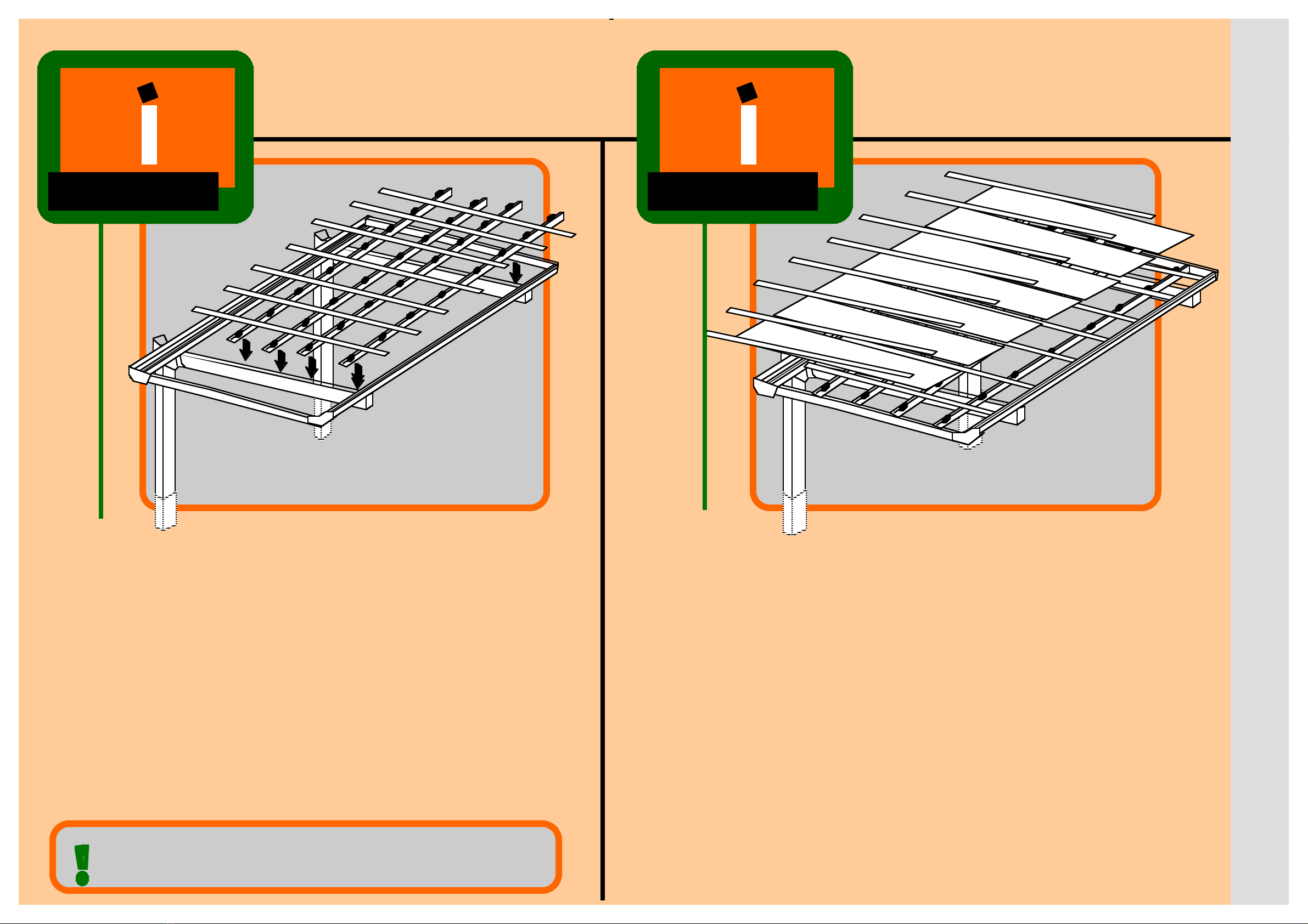
The base rafters are then fixed onto the bearers. Always start from the high end (fascia) and
work back to the gutter. The base rafter is required to be hard up against the top fascia to be
water tight. The bearer has a recessed cut out to which the base rafter rests on to. Repeat the
same procedure until all the rafters have been installed.
The frame now is ready for the next stage of the roof cover.
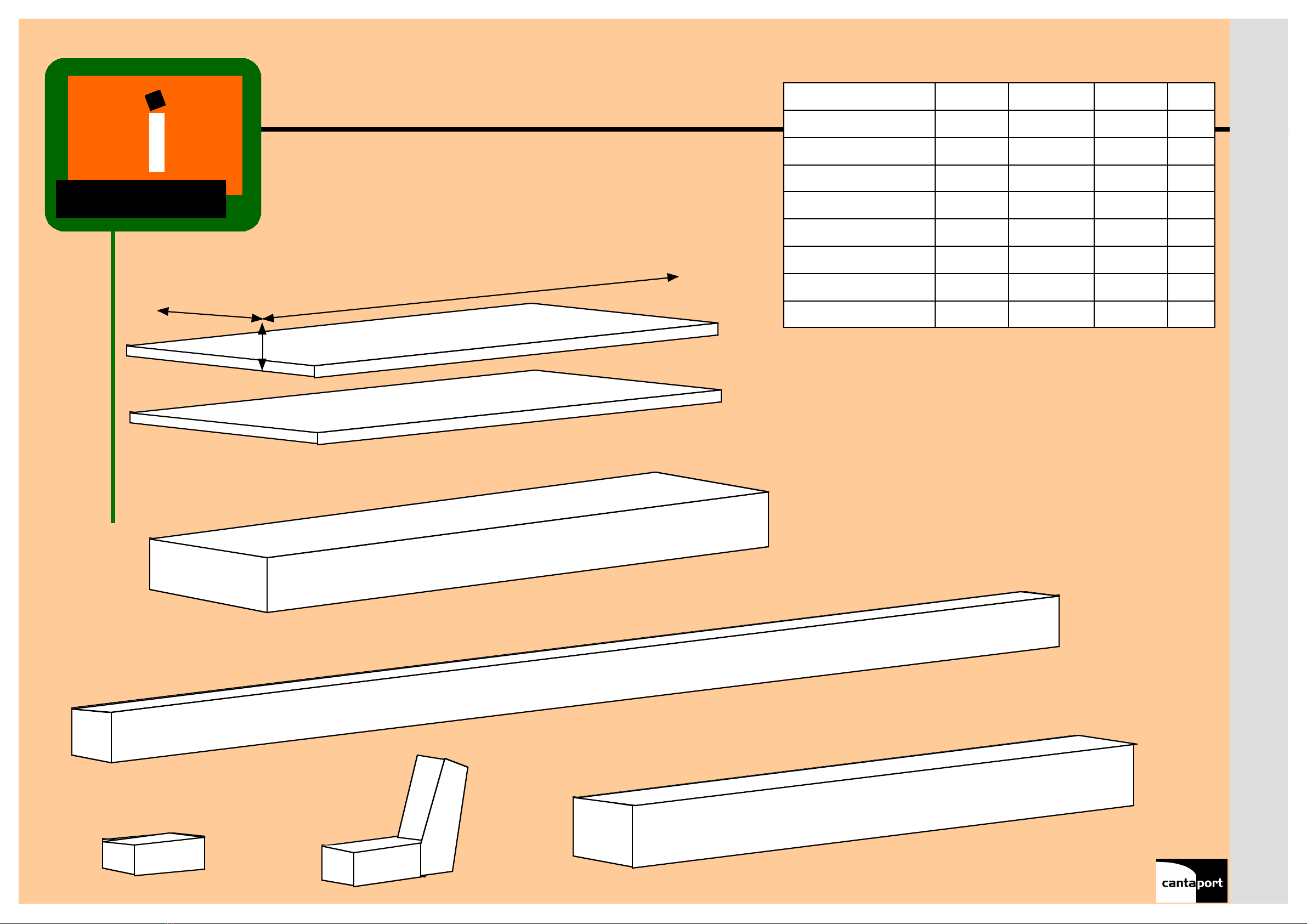
The final stage is the roof cover. The polycarbonated roof sheet blocks out 75% heat, 100%
UV rays and is considered hail proof. The sheeting is also very flexible for installation.
When installing the roof sheets, always make sure that you have access for the last sheet to
reach over to fix the cover rafter strip. If the cantaport is free standing without any structure
around the unit, you can start at either end. Should the side of the cantaport be situated against
a wall or structure with a restricted setback of less then 500mm, it is recommended that you
start from the restricted side.
The polycarbonated sheets have a protective plastic film on the top and bottom. On the
plastic film is a sticker indicating the side facing the sun. Always have that side of the sheet on
top of the cantaport. Peel the film from the top sheet after it has been installed. Always start
with the sheet inserted into the top fascia. Then let the sheet take shape over the bottom
rafters. Position the sheet equally onto the rafters and place the other end of the sheet into the
gutter. One side of the bottom rafter can then be fixed with the top rafter cover strip. Once you
have fixed all the screws into the top rafter cover strip, then continue the same procedure with
the remaining sheeting and top cover rafter strips.
The sheets should always be flat on the rafters without any gaps. The screws to the top cover
rafter strip should always be fixed correctly without any gaps. The screw is driven into a
channel that will connect the bottom and top rafter together. The process compresses and
holds the sheets together.
Finally black rubber seals are provided to be inserted to the underside of the sheeting. The
seals are pushed in between the rafters and the gutter. The down pipes provided can be
fixed to either post depending on the fall that was set out during the installation of the posts.
The protective plastic film can be removed from the sheets. Always refer to the manufactures
manual for more detailed information & instructions.
Always refer back to the manufacturers installation manual to determine the
correct fixing procedure and the type of screw fixing required.
step five
step six
d
.
.
cantaport
y
d
.
.
cantaport
y

flat pack
beams, fascia & rafters
Gutter, fascia & bearers
posts & down pipes
parts box
sheets x 3
sheets x 4
height
width
length
corner brackets
d
.
.
cantaport
y
All cantaport units are DIY, pre cut & pre drilled and packaged flat pack.
The flat pack displayed to the above table is the KCR5130 single basic.
KCR DIY 5130 Parts list
PART WIDTH LENGTH HEIGHT kg
Sheets x 3789 3000 50 20
Sheets x 4789 3000 52 23
Beams, fascia,rafters 450 3070 250 25
Gutter,fascia,bearers 250 5100 250 15
Parts box 150 350 120 1
Corner brackets 250 450 450 10
posts & down pipes 340 2800 280 15
TOTAL 120

This manual suits for next models
1
Other cantaport Shelter manuals
Popular Shelter manuals by other brands

ClearSpan
ClearSpan 4040SS manual

Shelters4Less
Shelters4Less SR1554 Assembly instructions

AMERICANA OUTDOORS
AMERICANA OUTDOORS COLONIAL Assembly instructions

Weka
Weka 663.2111.00.01 ASSEMBLY, USER AND MAINTENANCE INSTRUCTIONS

Lindab
Lindab Doorline installation manual

No Butts Bin
No Butts Bin SR1556-F Assembly instructions