D=3000
292575
2449.2 H18
2899.2H23
3399.2H28
150
P=715
L=4312
726 726
95
8562600856
H=1800H18
H=2250H23
H=2750H28
POST=H
L=5027
726 P=715 726
1063.52900
95
1063.5
H=1800H18
H=2250H23
H=2750H28
POST=H
KCR-PJR4330 KCR-PJR5030 KCR-PJR5830
TOP=H
H=1800H18
H=2250H23
H=2750H28
POST=H
TOP
L=5027
726 P=715 726
1063.52900
95
1063.5
H=1800H18
H=2250H23
H=2750H28
POST=H
900
D=2700
75 2625
2422.6H18
2872.6H23
3372.6H28
900
150
300
H=1800H18
H=2250H23
H=2750H28
POST=H
KCR-PJR5027
TOP=H
TOP
900
KCR-PJR2921 KCR-PJR5021
P=715
L=4312
726 726
95
H=1800H18
H=2250H23
H=2750H28
POST=H
856
2600
856
P=715
L=2882
726 726
95
2412400241
H=1800H18
H=2250H23
H=2750H28
POST=H
715
L=2167
726 726
133.5
95
1900133.5
KCR-PJR2221 KCR-PJR4321
140
300
800
2354.6H18
2804.6H23
3304.6H28
D=2100
2030
70
L=5027
726 P=715 726
1063.5
H=1800H18
H=2250H23
H=2750H28
POST=H
2900
95
1063.5
H=1800H18
H=2250H23
H=2750H28
POST=H
TOP=H
TOP
KCR-PJR WIDE BEAM
KCR-PJR WIDE BEAM TRIPLE
800
800 900
900
H=1800H18
H=2250H23
H=2750H28
POST=H
2485.8H18
2935.8H23
3435.8H28
D30+30D27+27
2449.2H18
2899.2H23
3399.2H28
2422.6H18
2872.6H23
3372.6H28
D33+33
900
150
300
3225
75
D1=3300
35
D2=3300
D1=3000
292575
D2=3000
2925 75
W=6035
3225 75
W=6635
PostInternalD33+D33=6335
150
D33+33
D30+30
PostInternalD30+D30=5735
PostInternalD27+D27=5135
PostCenteredD33+D33=6485
PostCenteredD30+D30=5885
PostCenteredD27+D27=5285
D27+27 W=5435
HEIGHT
900
D1=2700 D2=2700
75 2625 2625 75
D=3300
3225
75
L=5027 3.3m DEPTH ONLY
726 P=715 726
P=715
L=4312 SETOUT FOR 3.3m DEPTH ONLY
726 726 P=715 726
L=5742 3.3m DEPTH ONLY
726
TOP
H=1800H18
900
150
300
738.51775
95
1775738.5
900
H=1800H18
H=2250H23
H=2750H28
POST=H
95
8561300856 1300
H=1800H18
H=2250H23
H=2750H28
POST=H
871
95
2000 2000871
900
KCR-PJR4333 KCR-PJR5033 KCR-PJR5833
H=1800H18
H=2250H23
H=2750H28
POST=H
TOP=H
2485.8H18
2935.8H23
3435.8H28
H=2250H23
H=2750H28
POST=H
NOTE: 3300 WIDE MODELS REQUIRE 3 POSTS & 3 BEAMS
D2=3300
3225
75
D1=3300 W=6638
3225
75
D2=3000D1=3000 W=6038
29252925
2625
D2=2700D1=2700
2625
W=5438
38
75 75
75 75
38
38
H=1800H18
H=2250H23
H=2750H28
1000
150150
38
2485.8H18
2935.8H23
3435.8H28
D33+33
D30+30
D27+27
W=6638
W=6038
W=5438
D30+30D27+27
2449.2H18
2899.2H23
3399.2H28
2422.6H18
2872.6H23
3372.6H28
POST=H D33+33
NOTE: 3300 WIDE MODELS REQUIRE 3 POSTS & 3 BEAMS
1000
NOTE: 3300 WIDE MODELS REQUIRE 3 POSTS & 3 BEAMS
H=1800H18
H=2250H23
H=2750H28
POST=H
2515.3H18
2965.3H23
3465.3H28
900
150 Post Internal D80=7700 150
Post Centered D80=7850
300
D=8000
7575
7850
7050
7575
D=7200
Post Internal D72=6900
Post Centered D72=7050
2430.2H18
2880.2H23
3380.2H28
D=7200
D=8000
HEIGHT
L=5027
726 P=715 726
95
738.51775738.5 1775
900
8712000 2000871
W=5742
W=5027
L=5742
900 NOTE: WIDE BEAM TRIPLE MODELS REQUIRE 3 POSTS & 3 BEAMS
900
140 140
2374.1H18
2824.1H23
3324.1H28
2340.7H18
2790.7H23
3290.7H28
WB=51 WB=54 WB=60
H=1800H18
H=2250H23
H=2750H28
POST=H
Post Centered WB 51=4951.2
Post Centered WB 54=5266
Post Centered WB 60=5855.4
2436.8H18
2886.8H23
3386.8H28
4951.2 ( WB-51) 70
D=5406 (WB=54)
5266 (WB=54) 70
D=5091.2 (WB=51)
70
70
D=5995.4 (WB=60)
70
5855.4 (WB=60)
70
D=4815.4 (WB=48)
70
4675.4 (WB=48)
70
D=4223.2 (WB=42)
70
4083.2 (WB=42)
70
Post Internal WB 51=4811.2
Post Internal WB 54=5126
Post Internal WB 60=5715.4
Post Internal WB 42=3943.2
Post Internal WB 48=4535.4
Post Centered WB 42=3943.2
Post Centered WB 48=4675.4
4 POSTS
WB=48
2311.4H18
2761.4 H23
3261.4 H28
WB=42
2248.4H18
2698.4H23
3198.4H28
L=4312
L=5027
LENGTH
L=5742
L=4312
L=5027
LENGTH
L=5742
L=4312
L=5027
LENGTH
L=5742
HEIGHT
HEIGHT
HEIGHT
HEIGHT HEIGHT
HEIGHT
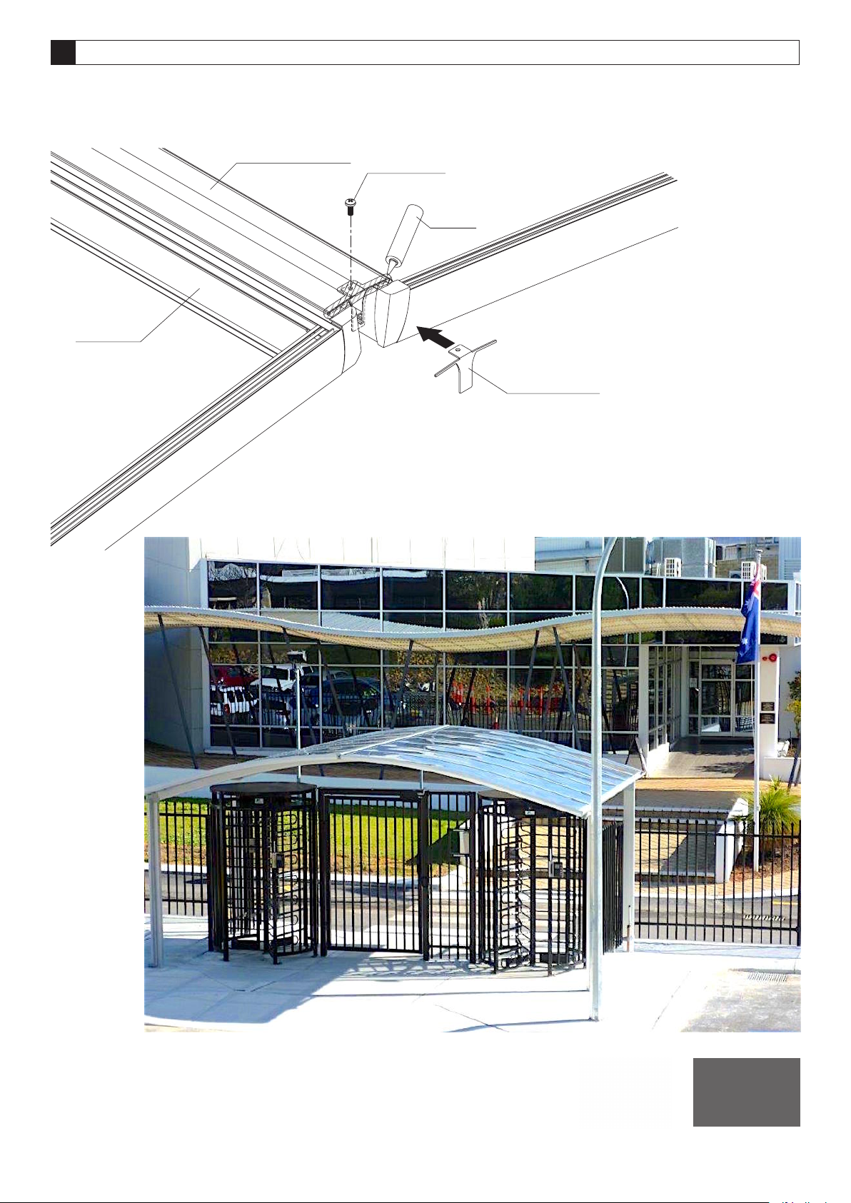
KCR-PJR M CONNECTION
KCR-PJR Y CONNECTION
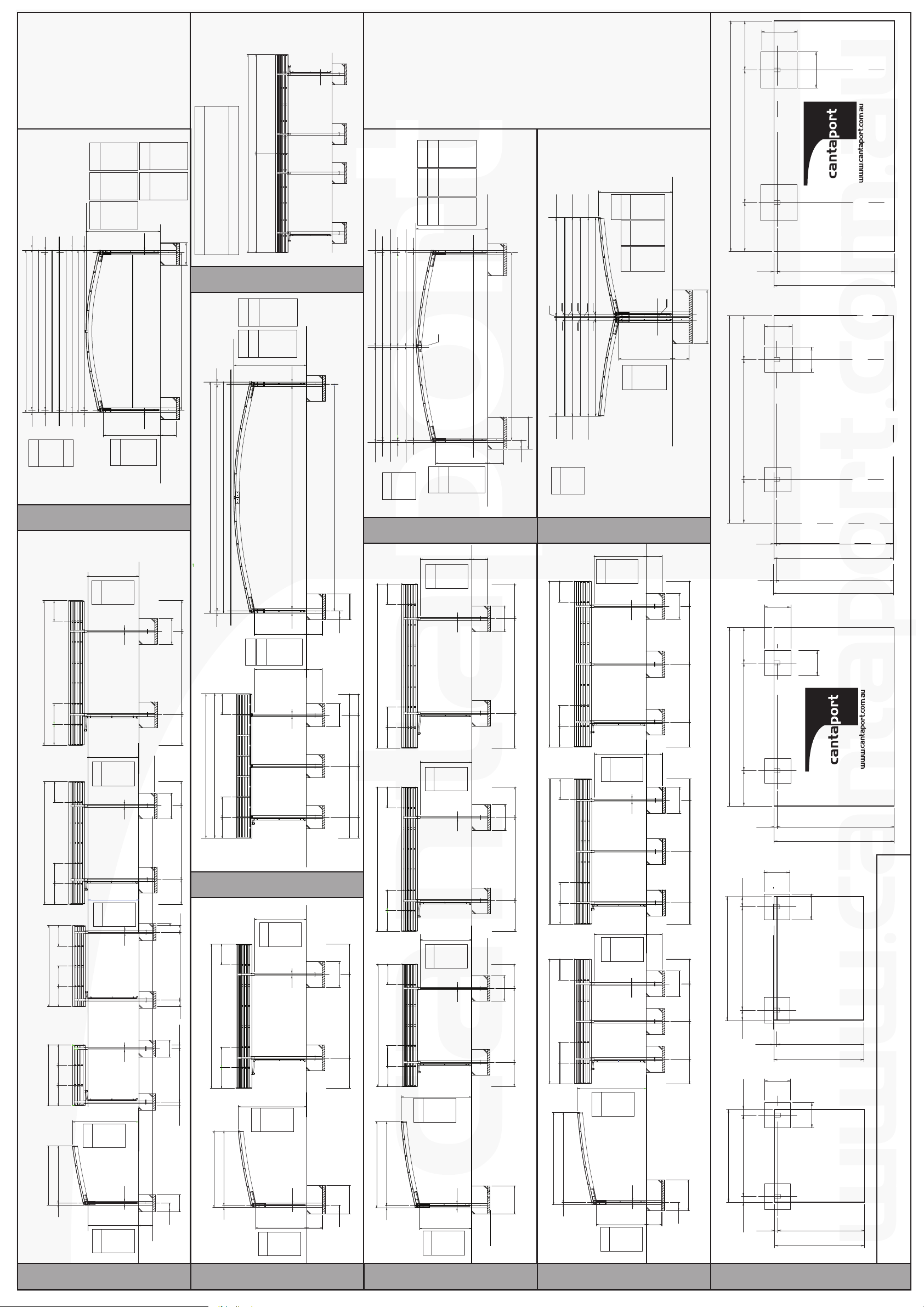
KCR-PJR DEPTH 2100KCR-PJR DEPTH 2700
KCR-PJR DEPTH 3000KCR-PJR DEPTH 3300
KCR-PJR Y CONNECTION KCR-PJR M CONNECTION
KCR-PJR WIDE BEAM TRIPLE
KCR-PJR WIDE BEAM
KCR-PJR INLINE
DEPTH & SETOUT AS PER INDIVIDUAL SERIES
KCR-PJR43 L43+43 = 4312+4312=L 8602
KCR-PJR50 L50+50 = 5027+5027=L10032
LENGTH
KCR-PJR57 L57+57 = 5742+5742=L11462
OVERALL LENGTH = L+L
95
L L
NOTE: 3300 WIDE MODELS REQUIRE 3 POSTS & 3 BEAMS
P=715 726
1221
95
1221
W=5742
726
3300
H=1800H18
H=2250H23
H=2750H28
POST=H
133.5133.5
600
1900
L=2167
600
D=2100
702030
241 2412400
L=2882
600
600
D=2100
702030
856 8562600
L=4312
900
900
D=3000 [3300]
752925 [3225]
1063.5 1063.52900
L=5027
900
900
D=2100
702030
3225 [2975] {2675} 75
D=3300 [3000] {2700}
75
1221
2925 [3225]
D=3000 [3300]
900
1221
L=5742
3300
900
900
900
900
900
900
KCR-PJRPLAN LAYOUT
L=22 L=29
L=43 L=50 L=57
General Notes :
1. Engineering drawings to be read
in conjuction with all architectural and
other specification drawings.
2. Any discrepancies shall be referred
to the engineer for confirmation prior
to commencing construction.
3. For setting out dimensions refer to
architectural drawings.No dimensions
to be obtained by scaling drawings.
4. All dimensions and levels to be
checked on site prior to commencing
any work.
5. All work to comply with the latest
Australian Standards and Buildng
Codes of Australia
6. Installation to be installed in
accordance with manufacturer's
printed assemling manual.
Foundations
1. All soil testing to be carried out by
the enginner soil type and conditions.
2. Remove all topsoil containing
vegetation & deletrious fill materail
from the building site.
Concrete Notes :
1. All concrete shall be in accordance
with the concrete structure code
AS 3600.
2. Blended cement (type GB) shall
conform with AS 3972 3. Water must
not be added to the mix to increase
the slump at any time.
3. Concrete shall be supplied by an
approved pre-mixed company and
conform to the following unless noted
otherwise :
GRADE SLUMP MAX. AGG.
FOOTINGS N20 80mm 30mm
METAL WORK NOTES :
1. All workmanship and materials
shall be in Accordance with
- AS/NZS 1866:1977-Aluminium and
Aluminium Alloys
- AS 1400-1998 Steel Structures
-AS/NZS 1665:2004 Welding Of
Aluminium Structures
- AS 1554.1 PT1 - Welding Of Steel
Structures
2. All hollow sections to be fully sealed
with 2mm plates, minimum, U.N.O
3. Erection of metal work shall be
commenced with braced bay and
erector shall provide all temporary
bracing required for the safe
completion of the work.
4. All bolts/screws/washers types and
their treatment of, is to comply with
all relevent australian standards
CERTIFICATION OF CANTAPORT KCR-PJR SERIES: THE CANTAPORT IS CERTIFIED FOR REGION A &TERRAIN CATEGORY2&3.
THE CANTAPORT IS DESIGNED ONLY WHEN THE POST IS BUILT IN THE FOOTINGS, BUT NOT ON CONCRETE SURFACES. THE
CANTAPORT STRUCTURE IS STUCTURALLY CAPABLE OF SUPPORTING THE DESIGN LOADS IN ACCORDANCE WITH ALL
RELEVENT AUSTRALIAN STANDARDS.
990000
900 900
900
900
900
900
900
900