manuals.online logo
Brands
  1. Home
  2. •
  3. Brands
  4. •
  5. Caple
  6. •
  7. Wine Cooler
  8. •
  9. Caple WI6230 Manual

Caple WI6230 Manual

Other Caple Wine Cooler manuals

Caple Wi6128 User manual

Caple

Caple Wi6128 User manual

Caple WC1800 User manual

Caple

Caple WC1800 User manual

Caple WF1104 User manual

Caple

Caple WF1104 User manual

Caple WC6510 User manual

Caple

Caple WC6510 User manual

Caple WI6130WH Manual

Caple

Caple WI6130WH Manual

Caple WI6126 Manual

Caple

Caple WI6126 Manual

Caple Wi6129 User manual

Caple

Caple Wi6129 User manual

Caple WF121 User manual

Caple

Caple WF121 User manual

Caple WI6226 User manual

Caple

Caple WI6226 User manual

Caple WI6234 User manual

Caple

Caple WI6234 User manual

Caple WC6410 User manual

Caple

Caple WC6410 User manual

Caple WI6143 User manual

Caple

Caple WI6143 User manual

Caple Wi6224 User manual

Caple

Caple Wi6224 User manual

Caple WI157 User manual

Caple

Caple WI157 User manual

Caple Wi6223 User manual

Caple

Caple Wi6223 User manual

Caple WI3126 User manual

Caple

Caple WI3126 User manual

Caple Wi6116 User manual

Caple

Caple Wi6116 User manual

Caple WI3150 User manual

Caple

Caple WI3150 User manual

Caple Wi3112 User manual

Caple

Caple Wi3112 User manual

Caple WF332 User manual

Caple

Caple WF332 User manual

Caple WC6100 User manual

Caple

Caple WC6100 User manual

Caple JLWF301 Manual

Caple

Caple JLWF301 Manual

Caple WI6134 User manual

Caple

Caple WI6134 User manual

Caple WI6161 User manual

Caple

Caple WI6161 User manual

Popular Wine Cooler manuals by other brands

Sub-Zero WS-30 Specification sheet

Sub-Zero

Sub-Zero WS-30 Specification sheet

Rotel U903CH1 Instructions for use

Rotel

Rotel U903CH1 Instructions for use

Esatto EWC46 quick start guide

Esatto

Esatto EWC46 quick start guide

Sub-Zero Classic Series installation guide

Sub-Zero

Sub-Zero Classic Series installation guide

U-Line Echelon Wine Captain 2075WC Features & benefits

U-Line

U-Line Echelon Wine Captain 2075WC Features & benefits

Haier WS50GA user manual

Haier

Haier WS50GA user manual

Cavist 62 instruction manual

Cavist

Cavist 62 instruction manual

Kenmore 461.99130 owner's manual

Kenmore

Kenmore 461.99130 owner's manual

Danby DWC113BLSDB owner's manual

Danby

Danby DWC113BLSDB owner's manual

Avanti WC1001 instruction manual

Avanti

Avanti WC1001 instruction manual

Frigidaire FFWC38F6LS Factory parts catalog

Frigidaire

Frigidaire FFWC38F6LS Factory parts catalog

Titan TT-W2454SZ User guide & service manual

Titan

Titan TT-W2454SZ User guide & service manual

Klarstein Botella 166 Uno manual

Klarstein

Klarstein Botella 166 Uno manual

Costway FP10130WL manual

Costway

Costway FP10130WL manual

Lemair LWC59 instruction manual

Lemair

Lemair LWC59 instruction manual

Vinvautz VZ08BHK user manual

Vinvautz

Vinvautz VZ08BHK user manual

Haier JC-125GEA user manual

Haier

Haier JC-125GEA user manual

Climadiff CLI24 use instructions

Climadiff

Climadiff CLI24 use instructions

manuals.online logo
manuals.online logoBrands
  • About & Mission
  • Contact us
  • Privacy Policy
  • Terms and Conditions

Copyright 2025 Manuals.Online. All Rights Reserved.

WI6230
Caple 60cm wine cabinet
Technical information
Item Part Code Description Qty
1DG12-37.1 Refrigerrant valve 1
2DG2-14 Power cord 1
3A DG7-47 Condenser fan 1
3B DG17-145-2 Electric wire 1
4DG19-3 Fan cover 1
5A DG1-93 Compressor 1
5B DG12-145 Start Device 1
5C DG12-146 Overload Protector 1
6DG13-403 Water tank 1
7DG6-19 Transformer 1
8DG3-97-6 PCB board 1
9DG13-272-1 junction box 1
10 DG14-190-SL Top hinge module (Left) 1
11 DG14-190-SR Top hinge module (Right) 1
12 DG12-44-2 Evaporator 2
WI6230 - Caple wine cabinet
13 DG7-48 Evaporator fan 2
14 DG22-209 Air duct board 2
15 DG19-6 Fan cover 2
16 DG13-198 Senser cover 2
17 DG8-8 Senser 2
18 DG3-12-W LED Light 2
19 DG13-383 Display holder 2
20 DG20-384 Display panel 2
21 DG13-1.2 Humid box 2
22 M160-049 Gasket 2
23 DG22-3064 Handle 2
24 DG22-3057 Door axis 2
25 DG23-172-1R Door (Right) 1
26 DG23-172-1L Door (Left) 1
27 DG15-27 Wooden shelves C1 2
28 DG15-26 Wooden shelves A15 8
29 DG15-26.1 Wooden shelves A15A 2
30
A
DG22-395 Electrical box 2
30B DG13-353 Sealing strip 2
31 DG14-212-SR Lower hinge module (Right) 1
32 DG22-330 Support bracket of front legs 1
33 DG14-212-SL Lower hinge module (Left) 1
34 DG12-91-2 Condenser 1
35 DG13-3146 Cabinet leg 4
36 DG12-113 Air-circulating pipe 2
37 DG22-331 Compressor bracket 1
38 DG11-46 Drier filter 1
-DG22-3021 Decorative frame 1
DG22 3302
1
--
DG22
-
3302
1
--- DG22-3303 1
1
ComputerControlledSynchronousDualTemperature
WinecoolerJG2D1
service manual
Herebelowwelistvariousfaultswhileusingthewinecellar,and themethod ofcheck-up andsolvethesedefaults,
pleasefindtheinformationofthecorrespondentpage.
Statement (Fig.4)showsthereferencefigureFig4
( →6)showsthereferencepage6
Warning:
1. Beforeattemptinganycleaningormaintenance thisunitMUSTbedisconnectedfromtheelectricalsupply,
topreventelectricalshock.
2. Beforeusingtheweldingtorchpleasemakesure thatthere isn tanygasinthecoolingsystems.
3. Beforeusingtheweldingtorchpleasedothenecessaryprotectionwell.Whenservicingthewinecooler
withR600asystems, pleasemakesuretheambient iswell ventilated.
▲Preparationbeforemaintenance
○Tools
1.Plier2.Cross-screwdraver
3.Assistantpipe4.Multimeter
5.Clampamperemeter(5A)6.Electriciron
7.Wireinsulatorstripper8.Pipesealplier
○Equipment
1.Vacuumpump2..Copepipeweldingfacility3.Refrigerantmeter
▲Cooling systemsfault
○Howtodiagnosethefaults (→2)
○Howtomaintainthefaults (→2)
○Howtoremovetheair-ductboards (→3)
○Diagramshowingthefrontsidesolderedjoints .(→5)
○Diagramshowingthebacksidesolderedjoints .(→5)
▲Noiseproblem
○Compressornoise(→6)
○Fannoise (→6)
○Refrigerantjetnoise (→7)
○Capillaryvibrationnoise (→7)
○Oil jamnoise (→7)
▲Evaporatorfreezing.(→8)
▲Theunstableofthewinecoolertemperature .(→8)
▲Thecontrolsystemfault
○Faultfindingbyself-checkmode .. (→8)
2
○Sensorfault .. (→9)
○Howtoreplacethesensor .. (→10)
○Refrigerantvalvefault .. (→10)
○LEDdisplayfault.. (→11)
○HowtoremovethepartsinsidethecontrolPCBelectricalbox .. (→11)
○ThenameandexplanationofthecontrolPCBand powerPCBboardconnectors (→12)
○HowtoremovethepowerPCBand transformer .. (→13)
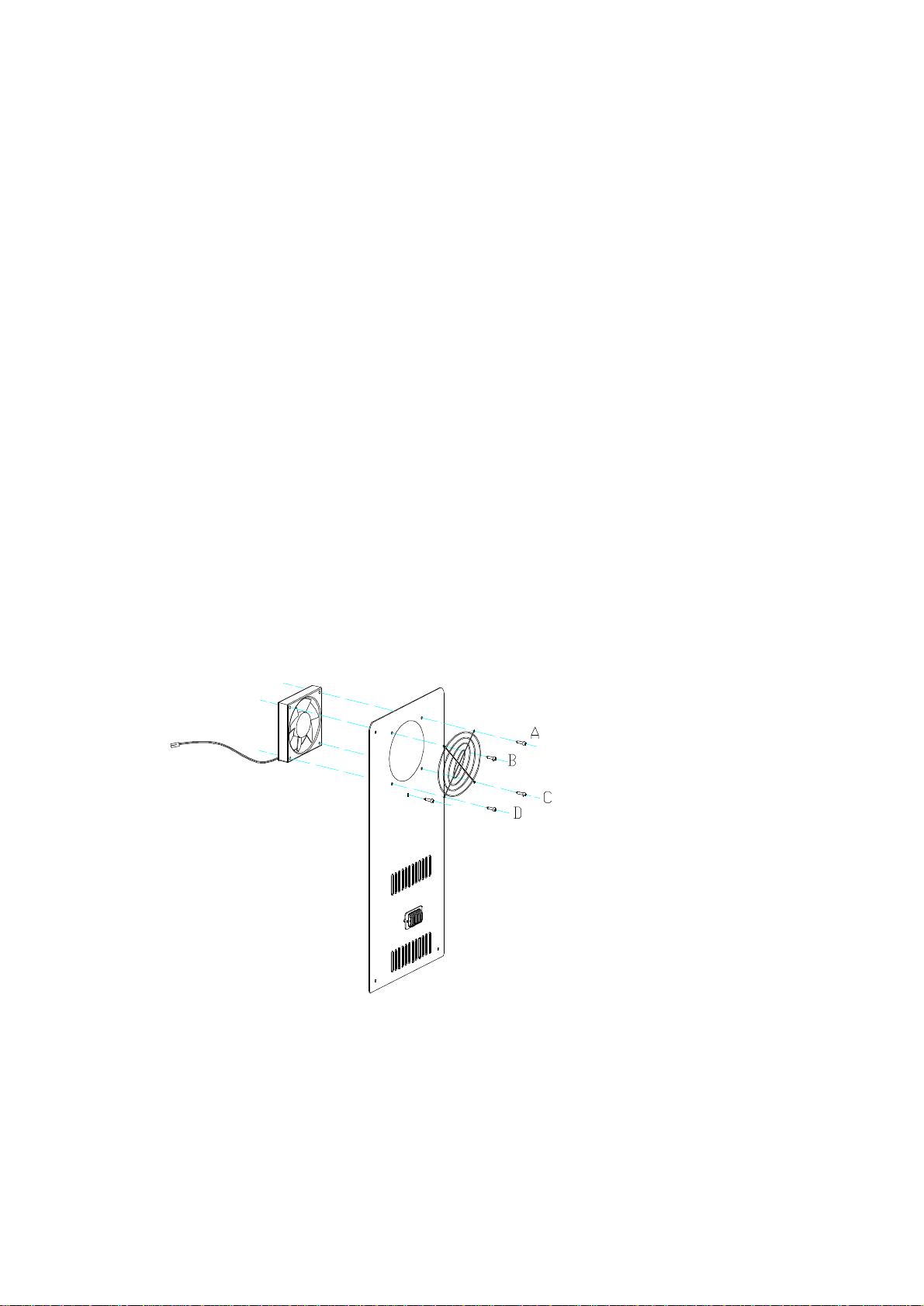
○HowtoreplacetheLEDlight .. (→14)
▲Thecontrolsystemfault
○Howtodiagnosethefaults
Itshouldtakeapproximate3hourstoreachthelowestsettingtemperatureof5℃foranemptyunitinboth
zone(assumingambienttemperatureof32 degreescentigradeandcontinuousoperation). If not, checkthecompressor,
cooling fans, controller, and sensors. If all theseareworkingnormally, thereisprobablya coolingsystemfault.
○Howtomaintainthefaults
1. Check the compressor:
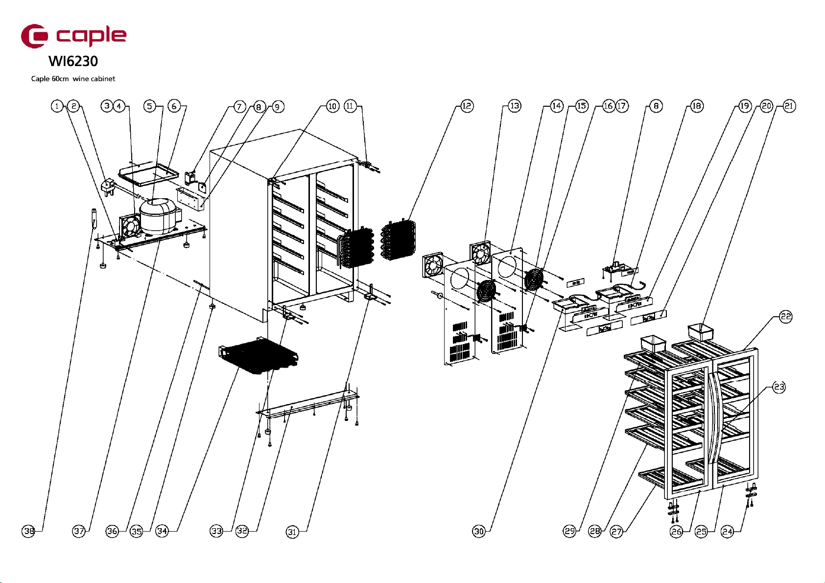
Theprocess ofcompress removed:removetheelectricalboxofcompressor→disconnecttheconnectorstothe
compressor→separatethepipejoints→removethecompressor
Theprocess ofevaporatorremoved:removetheshelves→removetheairductboard→separatethepipejoints
→removetheevaporator
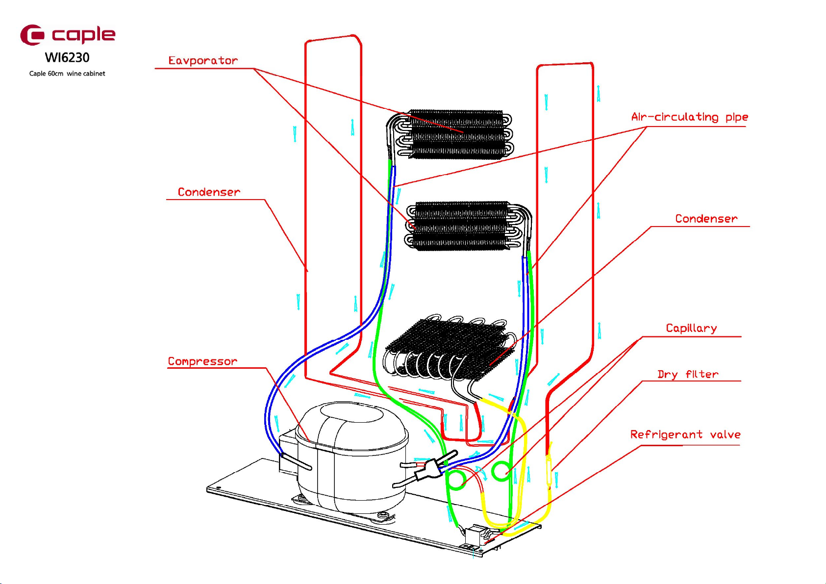
If neitherzonescannotrefrigerate,checkthecurrentofthecompressorwithaclampAmperemeter,and the
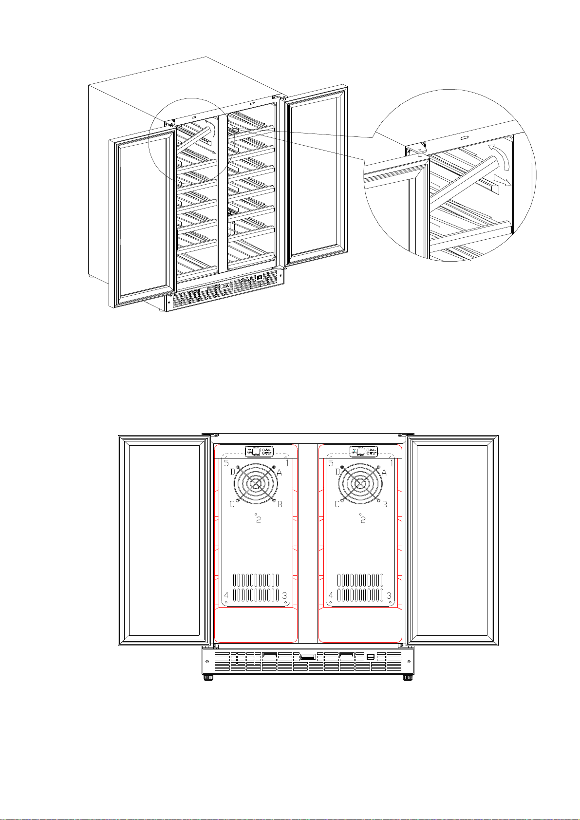
currentshouldbewithin0.8to2A.If thecurrentnotinthisrange,turnoffandcutofftheexhaust(Fig.4 ,see
point D) and assistant pipe(Fig.4 ,see point A), electrified the wine cooler and check the current
again, check thedischarge pipe of thecompressor at the sametime, if ithas an clear airpressure,
if the electricity is still too high or has not air pressure, it showsthat the compressoris
failed by itself,and you need to replace the compressor. (Noted:Toavoidthecompressorsuckthe
moist,runthecompressornotlongerthan15 minutesaftertheassistantpipeand dischargepipecutoff.)
2 .Check the cooling systempipe work.
1>.Under theconditionof thecompressorrunning normally,neither zone is not cooling.
and it is possibly that the cooling system pipe leak. The maintain procedure is following.
a. Cut the discharge pipe ofthe compressor.infill 0.8-1Mpa nitrogen via assistant
pipe, and feel the discharge pipe, there should be alittle airflow which means
the capillary is normal, otherwise the capillary is jam.
b .Make sure the capillary is in good condition, join the discharge pipe, infill
0.8-1Mpa nitrogen via the assistantpipe, check all the joints with soap water
if any leak from any of them. Check the back side joints around the compressor
first (Fig.4),if it without any leak check front side joints(Fig.3 ).Before
checking front side joints you needto remove the airduct board(Fig.1 &Fig.2).
c. If there isn’tany leakage can be found,it means two possible:1.the internal
leakage,2.theevaporatoror other part leakage.Internalleak can’tberepaired,
if the part (suchevaporator, condenser)leakage, replace it please.
d. Confirming thecooling system is in good condition, you refill again.
3
2>. Under the compressor is running normally,if only one zone no cooling, the fault
should happen on the part in this zone.(two zones have the same structure, so the
maintain method for them aresame).
a. Check the valve byhearing the sound.turnoffthe winecooler and exchange the
connectors ofthe valve thenpower on, listencarefully you canhear thesnip-snap
sound fromvalve,otherwise thevalveispower offor broken orthePCBfault.
Confirming the PCB is normal, replace the valve. (→8) (Fig.9)
b. If the valve is running normally, it maybe the capillaryjam, please clean it
with nitrogen, you can overhaul it referto above.
c. Replacethe fault spearparts.Confirmingthecoolingsystem isnotjammed, refill
the refrigerant.
3 .Refill
1>. Usingthevacuumpumpformavacuuminthesystem,viathejointofthelow-pressurepipe
(Fig.4,see point A),thehigh-pressurepipelineisontheprocess pipeofthefilter。Applythevacuum
pumpforapproximately20 minutes.Until thevacuumislowerthan100Pa. Thensoldertheprocess
pipeofthefilterKeepthethesystemvacuum.
2>. FillCooling systemwithrefrigerantviatheprocess pipe (Fig.4,see point A).Therefrigerant
and quantityPleaserefertotheinstructionatbacklabelofwinecellar.Thensolderthecompressor
process pipeafterthesystemischargedwithrefrigerant.
4 .Test
Replaceall thecomponentsaftertheproceduresaboveand turntheuniton.Toverifytheeffectiveness
oftherepair,monitortheunit,thecompressorshouldautomaticallystopwhenbothzone1.5℃lower
thansettingtemperaturesand startwheneitherzone2.5℃higherthan setting temperature within
approx3hours(assuminganambienttemperatureof32℃and theunitisempty).
○Howtoremovetheair-ductboards
1>.Pull theshelvestothebottom,circumvolveany sideoftherightand left,and letthesetteroftheshelvego
outofthechannel, and thendrawouttheshelves. (Fig.1)
4
2>.UseaSetofcross-screwdriverstoremovetheair-ductboardscrews(Note:1~5aretheair-ductboard
screws.A~Darethefanscrews,neednottoremove),and removetheair-ductboard.Beattentiontounplug
theconnectionwirewhenremovingtheair-ductboard.Youcanmoveslowlyasideuntil youcanseethefans
wire, andunplugthefanconnector,and thentakeoutthewholeair-ductboard. ;(Fig.2)
3>.Thepictureafterremovingtheairductboard. (Fig.3)
Fig. 1
Fig. 2
5
○Diagramshowingthefrontsidesolderedjoints(Fig.3)
A:CapillarysolderedjointB:Evaporatorsolderedjoint
○Diagramshowingthebacksidesolderedjoints(Fig.4)
A:CompressorassistantpipesolderedjointedB:Anti-dewpipesolderedjoint
C:RightzonesuctionpipesolderedjointD:Dischargepipesolderedjoint
E:LeftzonesuctionpipesolderedjointF:Condensersolderedjoint
G:FiltersolderedjointH:RightzonecapillarysolderedjointI:
ConnecterpipejointJ:Valvesolderedjoint
K:LeftzonecapillarysolderedjointL:Condensersolderedjoint
Fig. 3
Fig. 4
6
▲Noiseproblem
○Compressornoise
1>. Theworking ofmotorand pistonmotionwillcausenoisewhencompressorworking.Soifnoiseissteady
and notexceeds42dB,it’snormal.If noiseisnotsteadyorveryhigh,it’scompressorfault and itshould
bemaintainedorreplaced.
2>.Ifcompressor’sshockabsorptionrubberishardening ordamaged,orfixingscrewofcompressoristoo
tightorloose,itwillcausenoise.Thesettlementistochangenewshockabsorption rubberoradjust
fixing screws.
○Fannoise
1>.Therunningofthefanmotorwillcausenoisebecausethevanecircumvolveinhighspeedandtheairflow.
Normalfanmotorand airflowshouldnotexceed32 dB.
2>.If thenoiseisextremelybig, theremaybethefan’sfault, thereason isfollowing:
a. Theaxletreeofthefanbroken
b. Thebadbalancebecausethefansabrasion
3>.Thefancanbereplacewithanothersamemodel’sfan, theprocedureisfollowing:
a. Howtoreplacetheevaporatorfan.
Theprocess ofevaporatorfan removed:Removetheshelves→removetheairductboard→disconnecttheconnectors
→removethefancoverremovethefan.
1>.Removetheshelves. (→3)(Fig.1)
2> .Removetheairductboard. See (→3)(Fig.2)
3>.Removescrews(A,B,C,D),thenreplacetheevaporatorfanSee (Fig.2&Fig.5)
b. Howtoreplacethecondenserfan:
1>.Removethescrews(3,4),takeaparttheelectricalbox(A);(Fig.6)
2>.Pull offtheofthefanconnectoronthepowerPCB. (Fig.13)
3>.Leanbackthecabinet450,orputiton theworkbench,and usea Setofcross-screwdrivertowrest
off thetwoscrews(1,2)ofcompressorbottompenal,andremovethecondenserfantoreplacewithanewone.
(Fig.6&Fig.6.1)
Fig. 5