manuals.online logo
Brands
  1. Home
  2. •
  3. Brands
  4. •
  5. Caraudio-Systems
  6. •
  7. Car Video System
  8. •
  9. Caraudio-Systems TF-U500 User manual

Caraudio-Systems TF-U500 User manual

Version 10.03.2020 TF-U500
TV-Free
Universal video-in-motion Interface
TF-U500
Non p and p version for high speed CAN
Legal Information
By law, watching moving pictures while driving is prohibited, the driver must not be
distracted. We do not accept any liability for material damage or personal injury resulting,
directly or indirectly, from installation or operation of this product. This product should only
be used while standing or to display fixed menus or rear-view-camera video when the
vehicle is moving, for example the MP3 menu for DVD upgrades.
Changes/updates of the vehicle’s software can cause malfunctions of the interface. We
offer free software-updates for our interfaces for one year after purchase. To receive a free
update, the interface must be sent in at own cost. Labor cost for and other expenses
involved with the software-updates will not be refunded.
Version 10.03.2020 TF-U500
Page1"
Contents
1. Prior to installation
1.1. Delivery contents
1.2. Pin-assignments
1.3. Dip switch functions of the TV-500
2. Installation
3. Specifications
4. Technical support
1. Prior to installation
Read the manual prior to installation. Technical knowledge is necessary for installation. The
place of installation must be free of moisture and away from heat sources.
1.1. Delivery contents
With USB update-port for software-updates by consumer!
CAN-box TV-500
HW_____ SW_____
Harness
TV-UNI
Take down the SW-version and HW-version of the interface-boxes, and store this
manual for support purposes!
Version 10.03.2020 TF-U500
Page2"
1.2. Pin-assignments
Pin-assignment harness TV-UNI
Cable colour
Pin-No.
Assignment
● Yellow
Pin 4
CAN-HIGH – connection to the head-unit
● Blue
Pin 3
CAN-LOW – connection to the head-unit
●● Yellow/Black
Pin 8
CAN-HIGH – connection to the vehicle
●● Blue/Black
Pin 7
CAN-LOW – connection to the vehicle
● Red
Pin 1
+12V permanent
● Black
Pin 5
Ground
● Green
Pin 6
Activation of the video-in-motion function
(+12V = TV-free activated)
● White
Pin 2
Trigger output (+12V DC 500mA)
1.3. Dip switch functions of the TV-500
Dip 1 – activation TV-free
Dip 2 – no function (in some vehicles for rear-view camera)
Dip 3 – no function
Dip 4 – no function
Dip 5 – CAN-bus termination resistor on the vehicle side
Dip 6 – CAN-bus termination resistor on the head-unit side
Pin-assignment male 8pin connector of TV-500
Version 10.03.2020 TF-U500
Page3"
2. Installation
Switch off ignition and disconnect the vehicle’s battery! If according to factory rules
disconnecting the battery has to be avoided, it is usually sufficient to put the vehicle in
sleep-mode. In case the sleep-mode does not show success, disconnect the battery with a
resistor lead.
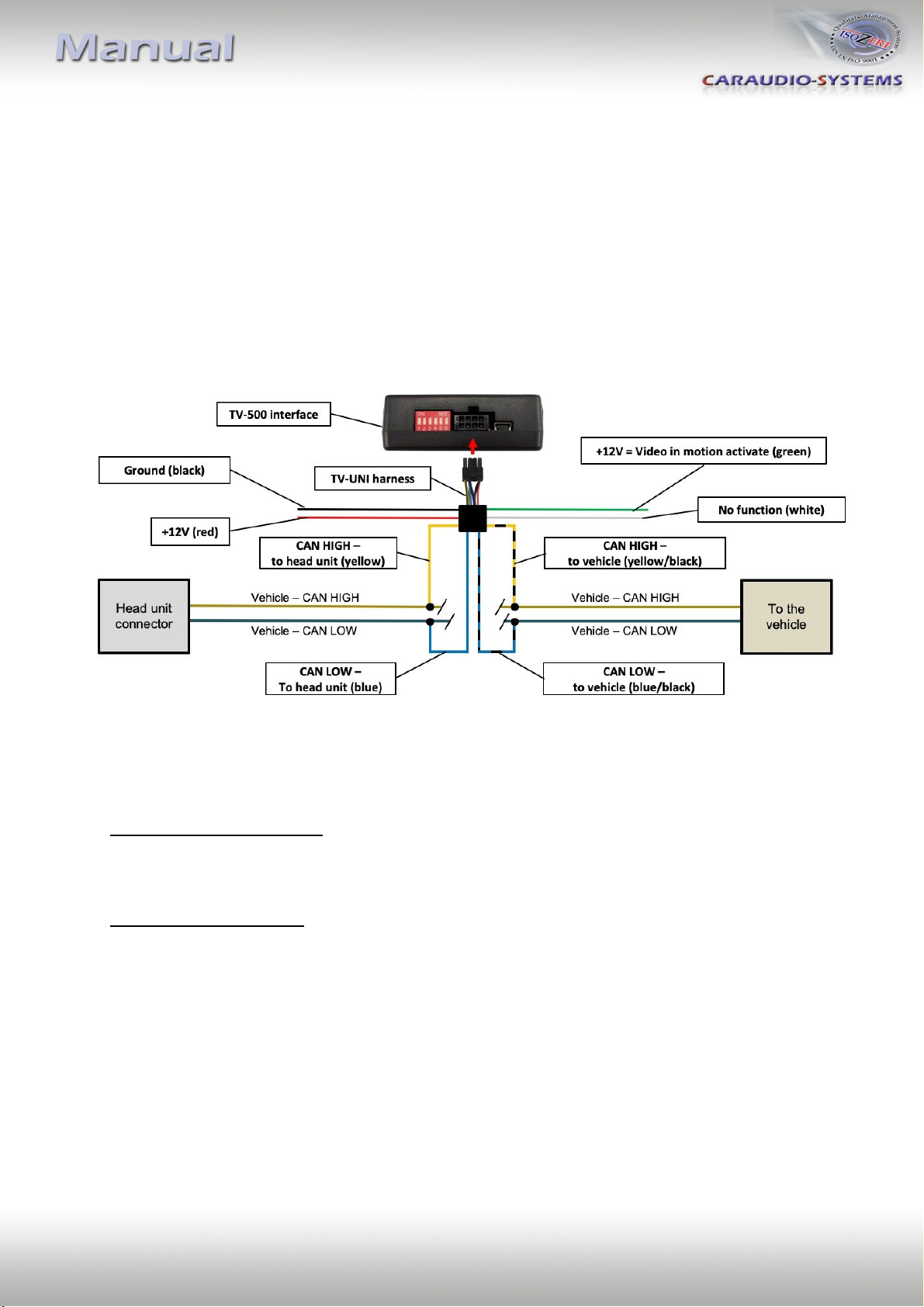
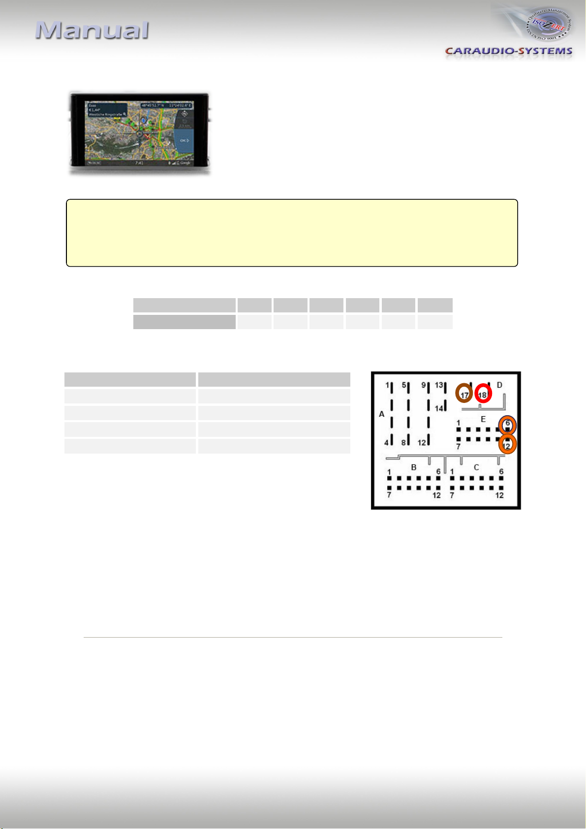
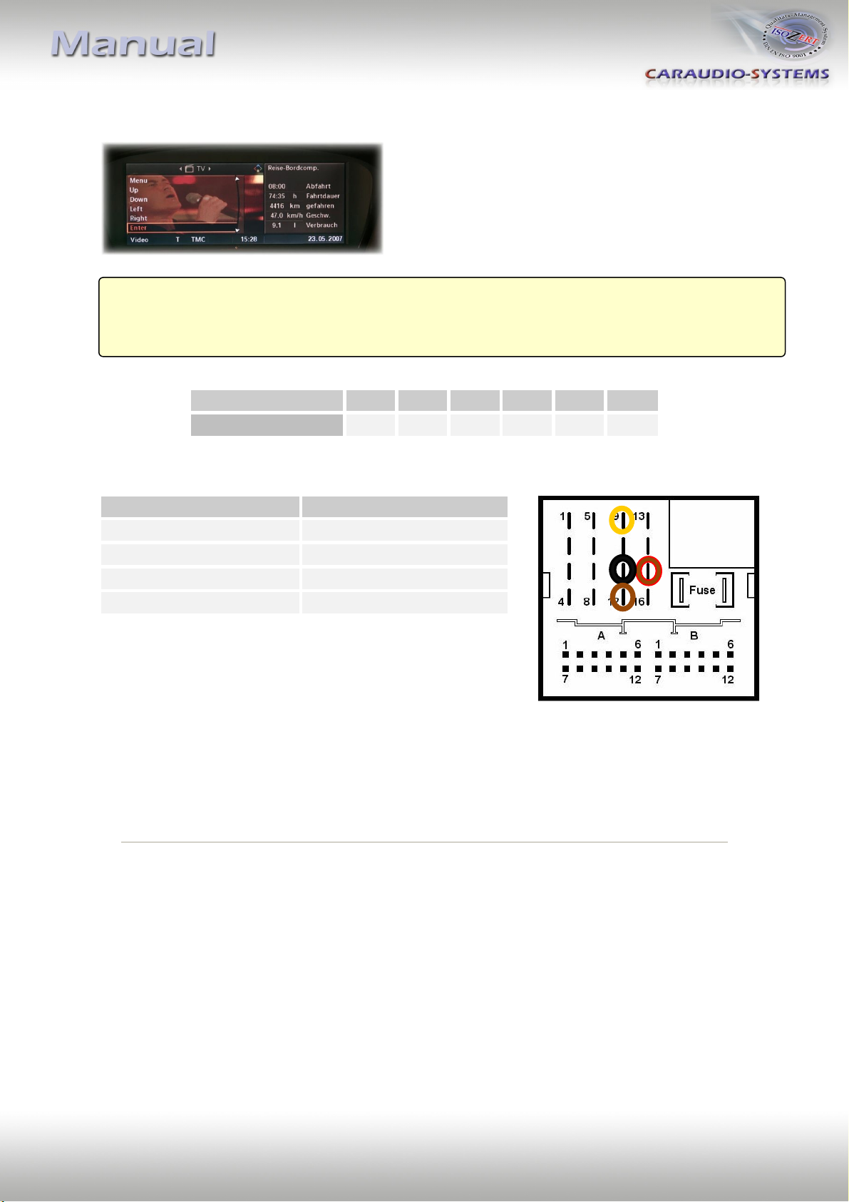
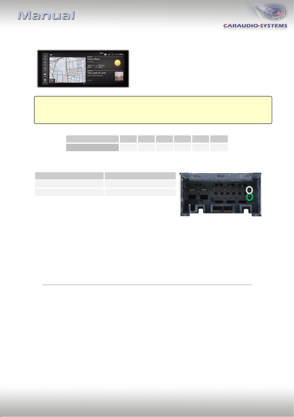
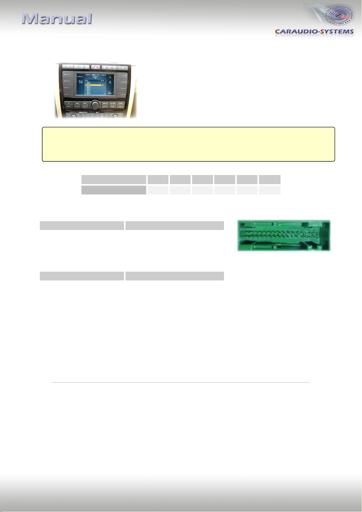
Install the interface at the CAN bus connection of the respective navigation system. Separate
the two CAN BUS cables (CAN-HIGH and CAN-LOW) from the navigation system and connect
them to harness TV-UNI (see picture below).
Connect the red wire to +12V permanent and connect the black wire to ground.
The video-in-motion can be activated and deactivated by Dip 1 or alternatively by the
included loose green cable in connection with a switch (not included in delivery).*
Video-in-motion permanent
With dip1 to ON the video-in-motion function is activated permanently without disturbing
the navigation performance.
Video-in-motion selective
With dip1 to OFF the included green cable is used to activate the video-in-motion function.
Connect a switch to the green cable and connect the green cable to +12V ACC.
● +12V = TV-Free is activated
● 0V = TV-Free is not activated
Note: The loose white cable is not required and must be isolated.
*Exception: On vehicles/navigation systems with Dip 1 must be set to OFF and video-in-
motion activation performs selectively by vehicle button, the activation by green cable
isn’t possible!
Version 10.03.2020 TF-U500
Page4"
Vehicles with Audi Navi Plus RNS-E
Place of installation is at the back side of the navigation unit.
Vehicle/ navigation
Dip 1
Dip 2
Dip 3
Dip 4
Dip 5
Dip 6
Navi Plus RNS-E
OFF
OFF
OFF
OFF
OFF
OFF
Cable colour
Assignment
●● Red/Yellow
+12Volt Permanent 15
● Brown
Ground Pin 12
●● Orange/Green
CAN HIGH Pin 9
●● Orange/Brown
CAN LOW Pin 10
No liability for vehicle wire colors and pin definition!
Possible changes by the vehicle manufacturer. The given
information must be verified by the installer.
Longpress the „>|“ button (about 5 seconds) to
activate/deactivate thevideo-in-motion function. When
ignition is off, the video-in-motion interface will be
automatically disabled.
Long blinking of the navigations backlight = TV Free ON
Short blinking of the navigations backlight = TV Free OFF
Note: While the video-in-motion function is activated, the navigation performance is not
possible!
Compatible vehicles Audi A3, A4, TT (8J)
Attention! Audi A6 with Navi Plus RNS-E have analog speed signal.
Version 10.03.2020 TF-U500
Page5"
Vehicles with Audi Navigation plus with MMI touch
Place of installation is at the back side of the navigation unit
Vehicle/navigation
Dip 1
Dip 2
Dip 3
Dip 4
Dip 5
Dip 6
MMI - MIB
ON
OFF
OFF
OFF
ON
ON
Cable colour
Assignment
● Red
+12V permanent Pin 18
● Brown
Ground Pin 17
●● Orange/Violet
CAN HIGH Pin 6
●● Orange/Brown
CAN LOW Pin 12
No liability for vehicle wire colors and pin definition!
Possible changes by the vehicle manufacturer. The given
information must be verified by the installer.
The video-in-motion function is activated permanently without disturbing the navigation
performance.
Compatible vehicles Audi
Navigation Navigation plus with MMI touch 7”
Version 10.03.2020 TF-U500
Page6"
Vehicles with Audi Navigation plus with MMI touch response
Place of installation is at the back side of the navigation unit
Vehicle/navigation
Dip 1
Dip 2
Dip 3
Dip 4
Dip 5
Dip 6
MMI - MIB
ON
OFF
OFF
OFF
ON
ON
Cable colour
Assignment
● Red
+12V permanent Pin 18
● Brown
Ground Pin 17
●● Orange/Violet
CAN HIGH Pin 6
●● Orange/Brown
CAN LOW Pin 12
No liability for vehicle wire colors and pin definition!
Possible changes by the vehicle manufacturer. The given
information must be verified by the installer.
The video-in-motion function is activated permanently without disturbing the navigation
performance.
Compatible vehicles Audi
Navigation MMI Navigation plus with MMI touch response 10,1”
Version 10.03.2020 TF-U500
Page7"
Vehicles with BMW NBT
Place of installation is at the back side of the
navigation unit.
Vehicle/ navigation
Dip 1
Dip 2
Dip 3
Dip 4
Dip 5
Dip 6
Professional NBT
ON
OFF
OFF
OFF
ON
ON
No liability for vehicle wire colors and pin definition!
Possible changes by the vehicle manufacturer. The given
information must be verified by the installer.
The video-in-motion function is activated permanently without disturbing the navigation
performance.
Cable colour
Assignment
●● Brown/Red
+12V permanent 15
● Brown
Ground Pin 12
● Black
CAN HIGH Pin 11
● Yellow
CAN LOW Pin 9
Compatible vehicles BMW 1series (F20/21), 3series (F30/31/32/33)
Navigation Navigation system Professional NBT with 8.8” monitor
Version 10.03.2020 TF-U500
Page8"
Vehicles with BMW MGU
Place of installation is at the back side of the
navigation unit.
Vehicle/ navigation
Dip 1
Dip 2
Dip 3
Dip 4
Dip 5
Dip 6
Professional MGU
ON
OFF
OFF
OFF
ON
ON
No liability for vehicle wire colors and pin definition!
Possible changes by the vehicle manufacturer. The given
information must be verified by the installer.
The video-in-motion function is activated permanently without disturbing the navigation
performance.
Cable colour
Assignment
● White
CAN HIGH Pin 9
● Green
CAN LOW Pin 16
Compatible vehicles BMW X5 (G05)
Navigation Navigation system Professional MGU
Version 10.03.2020 TF-U500
Page9"
Vehicles with ZAB
Place of installation is at the back side of the
navigation unit.
Vehicle/ navigation
Dip 1
Dip 2
Dip 3
Dip 4
Dip 5
Dip 6
All vehicles
ON
OFF
OFF
OFF
OFF
OFF
32-pin connector
8-pin power harness
No liability for vehicle wire colors and pin definition! Possible changes by the vehicle
manufacturer. The given information must be verified by the installer.
The video-in-motion function is activated permanently without disturbing the navigation
performance.
Cable colour
Assignment
●● Orange/Green
CAN HIGH Pin 16
●● Orange/Brown
CAN LOW Pin 32
Cable colour
Assignment
● Red
+12V Permanent Pin 7
● Brown
Ground Pin 8
Compatible vehicles Bentley Continental Coupe GT, VW Phaeton till about 03/2010
Navigation ZAB
Version 10.03.2020 TF-U500
Page10"
Vehicles with MYGIG
Place of installation is at the back side of the
navigation unit.
Vehicle/ navigation
Dip 1
Dip 2
Dip 3
Dip 4
Dip 5
Dip 6
All vehicles
ON
OFF
OFF
OFF
OFF
OFF
No liability for vehicle wire colors and pin definition! Possible changes by the vehicle
manufacturer. The given information must be verified by the installer.
The video-in-motion function is activated permanently without disturbing the navigation
performance.
Cable colour
Assignment
○● White/Orange
CAN-HIGH - Pin 13
○ White
CAN-LOW - Pin 2
● Red
+12V Permanent - Pin 1
●● Black/Green
Ground - Pin 12
Compatible vehicles Chrysler, Dodge and Jeep
Navigation MYGIG RER/REW/REN/REP/RHW
Version 10.03.2020 TF-U500
Page11"
Chrysler, Dodge, Jeep and Fiat Freemount with Uconnnect
Place of installation is at the back side of the
navigation unit.
Vehicle/ navigation
Dip 1
Dip 2
Dip 3
Dip 4
Dip 5
Dip 6
All vehicles
ON
OFF
OFF
OFF
OFF
OFF
Vehicles with 22pin connector on rear of head-unit
Vehicles with 52pin connector on rear of head-unit
No liability for vehicle wire colors and pin definition! Possible changes by the vehicle
manufacturer. The given information must be verified by the installer.
The video-in-motion function is activated permanently without disturbing the navigation
performance.
Pin No.
Assignment
Pin 7
CAN-HIGH
Pin 18
CAN-LOW
Pin 12
+12V Permanent
Pin 1
Ground
Pin No.
Assignment
Pin 2
CAN-HIGH
Pin 52
CAN-LOW
Pin 44
+12V Permanent
Pin 43
Ground
Compatible vehicles Chrysler, Dodge, Jeep, Fiat Freemount
Navigation Uconnect with 8.4” monitor with 22pin or 52pin connector on rear of
head-unit
Version 10.03.2020 TF-U500
Page12"
Vehicles with RT3-N3 CAN and RT4
Place of installation is at the back side of the
navigation unit.
Vehicle/ navigation
Dip 1
Dip 2
Dip 3
Dip 4
Dip 5
Dip 6
All vehicles
OFF
OFF
OFF
OFF
OFF
OFF
No liability for vehicle wire colors and pin definition!
Possible changes by the vehicle manufacturer. The given
information must be verified by the installer.
Longpress the “SRC”-button on the steering wheel (about 3 seconds) to activate/deactivate
the video-in-motion function. When ignition is off, the video-in-motion interface will be
automatically disabled.
Note: While the video-in-motion function is activated, the navigation performance is not
possible!
Cable colour
Assignment
● White
CAN HIGH Pin 10
● Grey
CAN LOW Pin 13
Compatible vehicles Citroen, Peugeot
Navigation RT3-N3 CAN, RT4
Version 10.03.2020 TF-U500
Page13"
Vehicles with NG4 NaviDrive and NG4 WipCom
Place of installation is at the back side of the
navigation unit.
Vehicle/ navigation
Dip 1
Dip 2
Dip 3
Dip 4
Dip 5
Dip 6
All vehicles
ON
OFF
OFF
OFF
OFF
OFF
No liability for vehicle wire colors and pin definition!
Possible changes by the vehicle manufacturer. The given
information must be verified by the installer.
The video-in-motion function is activated permanently without disturbing the navigation
performance.
Note: On some vehicles the navigation performance is affected and as long as the video-in-
motion function is activated the navigation will not be working! In this case you have to
connect the green cable as described in chapter “Exception: Vehicles with RT3-N3 CAN and
RT 4 without Source-button” and set Dip 1 to OFF.
Cable colour
Assignment
● White
CAN HIGH Pin 10
● Grey
CAN LOW Pin 13
Compatible vehicles Citroen, Peugeot
Navigation NG4 NaviDrive (Citroen), NG4 WipCom/WipNav (Peugeot)
Version 10.03.2020 TF-U500
Page14"
Ferrari California with MYGIG
Place of installation is at the back side of the
navigation unit.
Vehicle/ navigation
Dip 1
Dip 2
Dip 3
Dip 4
Dip 5
Dip 6
All vehicles
ON
OFF
OFF
OFF
OFF
OFF
No liability for vehicle wire colors and pin definition! Possible changes by the vehicle
manufacturer. The given information must be verified by the installer.
The video-in-motion function is activated permanently without disturbing the navigation
performance.
Cable colour
Assignment
○● White/Orange
CAN-HIGH - Pin 13
○ White
CAN-LOW - Pin 2
● Red
+12V Permanent - Pin 1
●● Black/Green
Ground - Pin 12
Compatible vehicles Ferrari California
Navigation MYGIG
Version 10.03.2020 TF-U500
Page15"
Ford Edge with MYGIG
Place of installation is at the back side of the
navigation unit.
Vehicle/ navigation
Dip 1
Dip 2
Dip 3
Dip 4
Dip 5
Dip 6
All vehicles
ON
OFF
OFF
OFF
OFF
OFF
Connector A
Connector B
No liability for vehicle wire colors and pin definition!
Possible changes by the vehicle manufacturer. The given
information must be verified by the installer.
The video-in-motion function is activated permanently without disturbing the navigation
performance.
Cable colour
Assignment
●● Grau/Orange
CAN-HIGH
●● Violett/Orange
CAN-LOW
Cable colour
Assignment
o● White/Red
+12V Permanent
●● Black/Blue
Ground
Compatible vehicles Ford Edge, Edge 2011
Navigation MYGIG
Stecker A
Stecker B
Connector A
Connector B
Version 10.03.2020 TF-U500
Page16"
Honda with HondaLink Next Generation Systems
Place of installation is at the back side of the
navigation unit.
Vehicle / navigation
Dip 1
Dip 2
Dip 3
Dip 4
Dip 5
Dip 6
All vehicles
ON
OFF
OFF
OFF
OFF
OFF
No liability for vehicle wire colors and pin definition!
Possible changes by the vehicle manufacturer. The given
information must be verified by the installer.
The video-in-motion function is activated permanently without disturbing the navigation
performance.
20pin connector
Assignment
Pin 13
CAN-HIGH
Pin 3
CAN-LOW
Compatible vehicles Civic, Fit (from model 2015)
Navigation HondaLink Next Generation Systems
1
20
Version 10.03.2020 TF-U500
Page17"
Jaguar XF with Touch-screen navigation version 2
Place of installation is at the back side of the
radio module.
Vehicle/ navigation
Dip 1
Dip 2
Dip 3
Dip 4
Dip 5
Dip 6
All vehicles
ON
OFF
OFF
OFF
OFF
ON
Attention: CAN-LOW and CAN-HIGH could be reversed at older
vehicles (e.g. Grey/Orange = CAN-LOW)!
No liability for vehicle wire colors and pin definition!
Possible changes by the vehicle manufacturer. The given
information must be verified by the installer.
The video-in-motion function is activated permanently without disturbing the navigation
performance.
Cable colour
Assignment
●● Yellow/Red
+12V Permanent
● Black
Ground
●● Grey/Orange
CAN-HIGH
●● Purple/Orange
CAN-LOW
Compatible vehicles Jaguar XF
Navigation Touch-screen navigation version 2
Version 10.03.2020 TF-U500
Page18"
Jaguar XJ and XF with Touch-screen navigation version 3
Place of installation is at the back side of the
monitor.
Vehicle/ navigation
Dip 1
Dip 2
Dip 3
Dip 4
Dip 5
Dip 6
All vehicles
ON
OFF
OFF
OFF
OFF
ON
No liability for vehicle wire colors and pin definition!
Possible changes by the vehicle manufacturer. The given
information must be verified by the installer.
The video-in-motion function is activated permanently without disturbing the navigation
performance.
Cable colour
Assignment
●● Grey/Red (Pin 8)
+12V Dauerplus
● Black (Pin 5)
Masse
●● Grey/Orange (Pin 2)
CAN-HIGH
●● Purple/Orange (Pin 1)
CAN-LOW
Compatible vehicles Jaguar XF X250 (from model 2012), XJ X351 (from model 2011)
Navigation Touch-screen navigation version 3
Version 10.03.2020 TF-U500
Page19"
Jaguar with INCONTROL TOUCH PRO
Place of installation is at the back side of the
navigation unit (trunk, left side).
Vehicle/ navigation
Dip 1
Dip 2
Dip 3
Dip 4
Dip 5
Dip 6
All vehicles
ON
OFF
OFF
OFF
ON
ON
Note: Dip switch functions of the TV-500
Dip 1 – activation TV-free
Dip 2 – no function
Dip 3 – no function
Dip 4 – no function
Dip 5 – CAN-bus termination resistor on the vehicle side
Dip 6 – CAN-bus termination resistor on the head-unit side
Pin-assignment
No liability for vehicle wire colors and pin definition! Possible changes by the vehicle
manufacturer. The given information must be verified by the installer.
The video-in-motion function is activated permanently without disturbing the navigation
performance.
Cable colour
Assignment
●● Purple/Green
CAN-HIGH - Pin17
●● Purple/Gray
CAN-LOW - Pin16
● Yellow
+12V Permanent - Pin3
● Black
Ground - Pin1
Compatible vehicles Jaguar F-Pace
Navigation INCONTROL TOUCH PRO (10” monitor)

This manual suits for next models

1

Other Caraudio-Systems Car Video System manuals

Caraudio-Systems CAN-Box TV-500 User manual

Caraudio-Systems

Caraudio-Systems CAN-Box TV-500 User manual

Caraudio-Systems usbLOGiC USB-MFD2-R1 User manual

Caraudio-Systems

Caraudio-Systems usbLOGiC USB-MFD2-R1 User manual

Caraudio-Systems TF-PCM31 User manual

Caraudio-Systems

Caraudio-Systems TF-PCM31 User manual

Caraudio-Systems CI-TF-NTG6 User manual

Caraudio-Systems

Caraudio-Systems CI-TF-NTG6 User manual

Caraudio-Systems RL-UCON22-TF User manual

Caraudio-Systems

Caraudio-Systems RL-UCON22-TF User manual

Caraudio-Systems ZL-MYGIG-V2-R User manual

Caraudio-Systems

Caraudio-Systems ZL-MYGIG-V2-R User manual

Caraudio-Systems TF-UCON52 User manual

Caraudio-Systems

Caraudio-Systems TF-UCON52 User manual

Caraudio-Systems RL-MFD1 User manual

Caraudio-Systems

Caraudio-Systems RL-MFD1 User manual

Caraudio-Systems TF-RTI11 User manual

Caraudio-Systems

Caraudio-Systems TF-RTI11 User manual

Popular Car Video System manuals by other brands

Farenheit Mobile Video System owner's manual

Farenheit

Farenheit Mobile Video System owner's manual

Sony PCS-11 operating instructions

Sony

Sony PCS-11 operating instructions

Ten-Haaft Oyster operating instructions

Ten-Haaft

Ten-Haaft Oyster operating instructions

Sony XVM-R75 operating instructions

Sony

Sony XVM-R75 operating instructions

NavInc NAVplay NP6-RR-3GH manual

NavInc

NavInc NAVplay NP6-RR-3GH manual

Stinger HEIGH10 UN1810E-FD5 installation guide

Stinger

Stinger HEIGH10 UN1810E-FD5 installation guide

Soundstream VIR-7830B owner's manual

Soundstream

Soundstream VIR-7830B owner's manual

Clarion NX807 owner's manual

Clarion

Clarion NX807 owner's manual

JVC KV-M705 instructions

JVC

JVC KV-M705 instructions

Pyle view PLVWR950T instruction manual

Pyle view

Pyle view PLVWR950T instruction manual

AVA Enterprises Universal Headrest user manual

AVA Enterprises

AVA Enterprises Universal Headrest user manual

JVC KW-AV71BT Installation & connection manual

JVC

JVC KW-AV71BT Installation & connection manual

Kia ATBA0HYAN Quick reference guide

Kia

Kia ATBA0HYAN Quick reference guide

NavLinkz r.LiNK RL4-MIB100 manual

NavLinkz

NavLinkz r.LiNK RL4-MIB100 manual

Protex Prosecutor 2000 AVE-8002 Operation manual

Protex

Protex Prosecutor 2000 AVE-8002 Operation manual

Kia Sorento 2011 Features & functions guide

Kia

Kia Sorento 2011 Features & functions guide

Boss Audio Systems Road Show RS70DVDT user manual

Boss Audio Systems

Boss Audio Systems Road Show RS70DVDT user manual

Panasonic CXDV700U - CAR DVD PLAYER operating instructions

Panasonic

Panasonic CXDV700U - CAR DVD PLAYER operating instructions

manuals.online logo
manuals.online logoBrands
  • About & Mission
  • Contact us
  • Privacy Policy
  • Terms and Conditions

Copyright 2025 Manuals.Online. All Rights Reserved.