Carbide 3D HDZ 3.3 User manual

HDZ 3.3 Assembly Guide
Intro
Thank you for purchasing a HDZ. We hope you enjoy your purchase!
● If you have any issues following these instructions please contact suppo[email protected].
● Prior to fitting the HDZ, please ensure you can rotate the ball screw by hand and move the carriage to
the top and bottom of the carriage - if you cannot do this please contact us on
● If you have any issues with your HDZ upon setup such as binding or movement please contact
[email protected] - we request you do not attempt to diagnose or dismantle the HDZ.
● Note to install CM you are required to run Carbide Motion 4.17 onwards. The latest version of Carbide
Motion can be downloaded from the below link.
https://carbide3d.com/carbidemotion/download/
To carry out this modification you need basic mechanical skills and an understanding of how the Shapeoko is
assembled. The installation should take under 2 hours. You will need basic shop tools and a metric set of allen keys
and spanners (the tool kit that came with your Shapeoko should be adequate).
We have created a quick overview video which will give you an indication of the process.
https://youtu.be/ojVpMMRCeVU
Your HDZ comes 95% ready to fit, however a number of parts (listed below) will need to be transferred from your
existing Z/X axis. As of this posting the HDZ comes with replacement guide bearings and spacers. These no longer
need to be removed as stated in the video.
Please use the screws provided. Note the screws used are METRIC, usually M5.
This process is uniform across the Shapeoko 3, 3XL and 3XXL.
Once fitted please ensure GRBL settings have been changed. DO NOT HOME UNTIL THIS HAS BEEN DONE.
Your HDZ should come with green caps pre fitted to the rails - if they have not been fitted you will want to do this
yourself. You might need to use a small dab of rubber based adhesive or CA glue. In most cases, they can be pressed
in using the flat side of a screw driver.


Contents
Each HDZ comes with the following hardware as standard (this is all required to attach it to your Shapeoko). As of
October the only items you need to transfer from your existing X/Z is the homing switches, X/Z motors, spindle.motor
and mount.
● 1 x EZTram Dewalt/Makita/Carbide Compact Router spindle mounting plate
● 2 x M5 18mm screws for the top of EZTram plate
● 2 x M5 10mm screws for the bottom of EZTram plate
● 2 x Eccentric spacer for EZTram
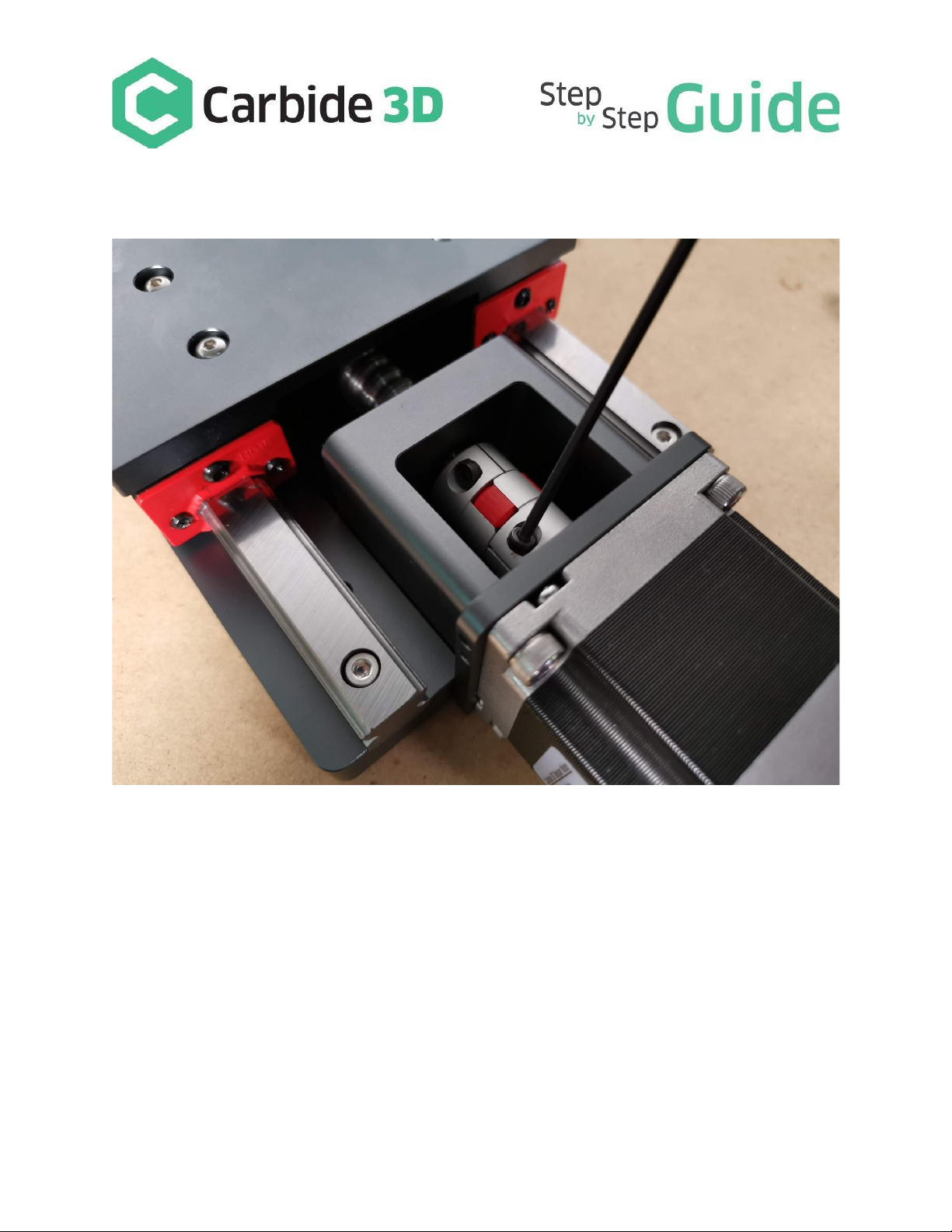
● Shaft coupler
● 4 x 40mm Z motor supports
● 4 x 25mm X motor supports
● 8 x 10mm M5 Screws for motor stand-offs
● 2 x HD Eccentric nuts
● 4 x Replacement V-wheel
● 4 x V-wheel shim
● 4 x M5 x 25mm Screw for V-wheels
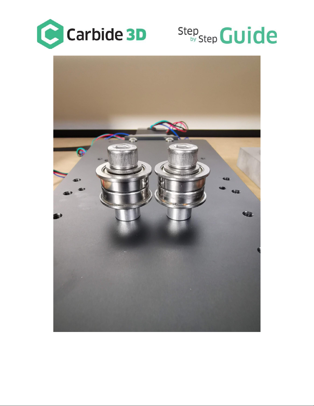
● 2 x M8 30mm X pulley screws
● 2 x M8 Washer
● 2 x M8 Spacer
● 4 x M8 guide bearings
● 4 x Black sledge - this is used if you have to remove a carriage
Removal
Your first step is to remove your existing X/Z carriage from your Shapeoko. To do this;
● Turn off your machine and unplug it.
● Disconnect the router or spindle and remove it from the spindle mount.
● Remove one side of your X axis belt tensioners and place the belt from the X axis to one side.
● Label, then disconnect Z and X motors. Remove your Z and X Homing switches from the Z/X carriage along
with the drag chain bracket.
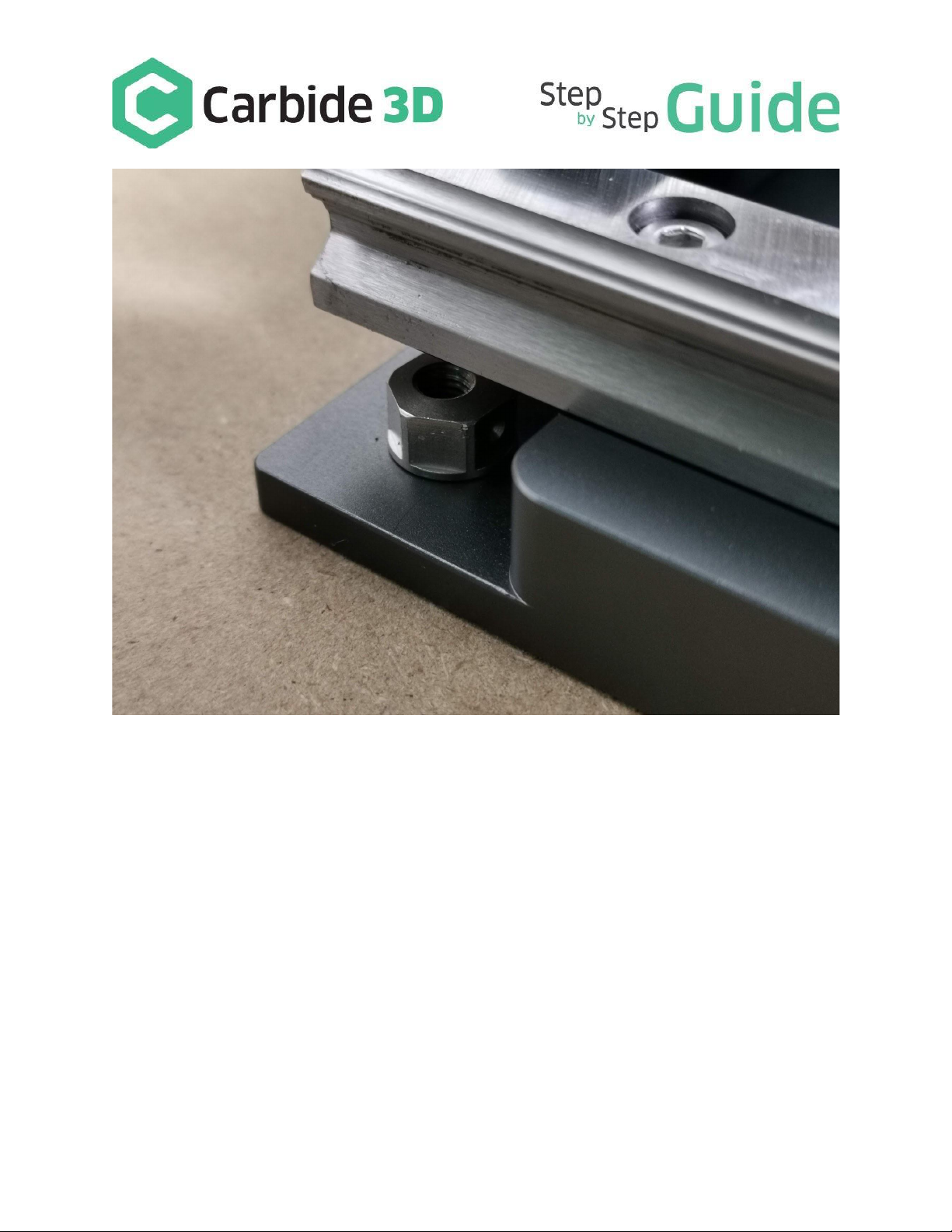
● To remove the axis loosen and remove your lower eccentric nuts and bottom V-wheels from the bottom of the
axis and remove.
● Your Z/X can now be lifted off your machine.
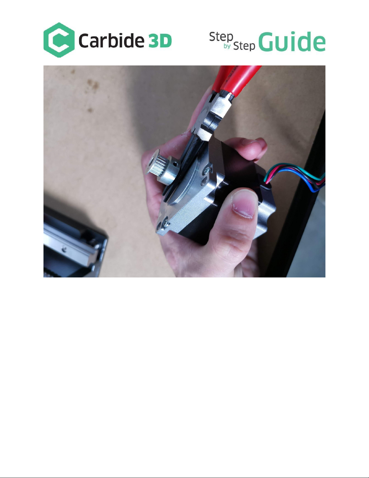
● Remove the X and Z motors from the old axis and disconnect.
The Z motor will have a gear pulley on it. Loosen the two small grub screws. In some cases this will still be hard to slide
off. We recommend using a screwdriver or needle nose pliers or the back of a claw hammer to lever it off. Once the
motors are off, also remove the spindle mount and screws.

Assembly Tip
Upon assembly it’s up to you if you use thread lock we suggest adding it after if any screws become loose. If you decide
to use thread lock use blue – i.e. light/medium grade.
The quickest and easiest way to fit the HDZ is to assemble the majority components to the HDZ prior to fitting the HDZ
to the Shapeoko.
Eccentric Nuts
Fit the two supplied M5 Eccentric threaded nuts and press them into the holes on the bottom of the HDZ. Rotate them
so the dimples face upwards - this is the loose position.

Z Motor and Coupling
● 4 x M5 Screw
● Z motor
● Z Motor Coupling
Placing the new coupler on the ball screw slide it down as far as it goes and tighten the lower side of the coupler.

Slide your motor shaft onto this coupler and position the 4 x 10mm M5 screws. Tighten these in a cross pattern.


Once the motor is fitted, tighten the coupling at the motor side. Note you need to ensure these are tight, failure to do
so will lead to slippage. A small amount of blue thread lock on the motor shaft and ball screw shaft won’t do any harm.
X Pulleys and Supports
● 2 x M8 Bolt

● 2 x M8 Washer
● 2 x M8 Spacer
● 4 x M8 Support Bearing
Fit the two washers to the screws first then the 4 bearings finally finishing with the with the M8 spacers. Once the
screws are assembled fit these screws to your HDZ to the two M8 holes.
Fitted correctly your mounts should look like the below and the screws will not poke through the front of the plate.

Note the Screw head/Washer/flanged Bearings//Spacer combination.

X Motor Supports
● 4 x M5 25mm supports
There are four threaded holes in the center of the carriage just above the M8 bolts. Insert the 4 x 25mm motor supports
into the 4 holes. Please note these are aluminum. Do not over-tighten them.
When the spacers have been fitted, fit your X motor using the 4 x M5 x 10mm screws provided. As a tip, it's easier to
fit the motor at the same time as re-fitting the belt.

Assembly: V-wheels
4 x V-wheels
● 4 x M5 Shim
● 4 x M5 x 25mm screw
The HDZ comes with a spare set of V-wheels, you can use these or your old ones.
Fit the top two V-wheels first using the provided 25mm M5 screws. Ensuring there is a shim between the back plate
and the V-wheel.

When the top V-wheels have been fitted, lift the carriage onto the X axis beam. Then fit the bottom V-wheels in the
same fashion. As you fit them ensure the V-wheel grooves are on the rail.
Once fitted ensure the axis moves freely left/right. To properly seat the axis, tighten the lower M5 screws - as they
tighten they will rotate the eccentrics, applying pressure to the v-wheels. The v-wheels should move freely as you move
the axis. If you need to, hold the screw in place and rotate the eccentric a fraction. Shims - If your V-wheels are not
turning freely check the shims are fitted correctly.

X Motor
● 4 x M5 x 10mm screw
● X Motor
Start by threading your belt, creating a large loop, then fit your X motor using the 4 x M5 screws.


X Belt
As the carriage is on the extrusion and the belt is in place you can re-fit the X belt. It should be taut.

Drag Chain Support
Re-fit the drag chain support using the two M5 screws from your bracket.

X Homing Switch
Use your existing M5 bolts and spacers to fit the X homing switch to the new carriage as before. There are two threaded
M5 holes on the right-hand side of the carriage.

Motors
Re connect your X and Z motors, ensuring each one is correct. Then tidy up your wiring.

Spindle Mount
● Spindle Mount & screws
● 2 x M5 x 18mm screws
● 2 x M5 x 10mm screws
● 2 x M5 non threaded eccentric nut
The EZTram spindle mount is a great feature on the HDZ. It’s easy to fit and makes tramming your spindle a lot easier
utilizing 2 eccentric spacers.
Using your existing spindle mount and screws, fit it to the new EZTram mount, ensuring the recessed holes
accommodate the screw heads, and tighten. Feel free to use some thread lock here.
Other manuals for HDZ 3.3
1
Table of contents
Other Carbide 3D 3D Printer manuals