Carefree FREEDOM WM AWNING User manual

INSTALLATION MANUAL
FREEDOM WM AWNING
MOTORIZED OR MANUAL LATERAL ARM BOX AWNING
RV
TABLE OF CONTENTS
Safety Information................................................................................................................................... 2
Product Overview.......................................................................................................................... 1
Component Checklist.............................................................................................................................. 2
Installation ..................................................................................................................................... 3
Attaching the Mounting Plates ................................................................................................................ 3
Mounting the Awning ...................................................................................................................... 4
Installation Using an Awning Rail........................................................................................................... 5
Bottom Bracket Installation ..................................................................................................................... 6
Manual Crank Handle Storage Clips ...................................................................................................... 6
Switch Installation (motorized awnings only)............................................................................. 7
Optional LED Lighting ................................................................................................................... 8
Switch Installation................................................................................................................................... 8
Pitch Adjustment ........................................................................................................................... 9
Manual Override (motorized versions only)................................................................................ 9
Setting the Motor Limits ............................................................................................................. 10

Adjusting the OUT Limit Switch .................................................................................................... 10
Adjusting the IN Limit Switch ........................................................................................................ 10
052563-001r9 Printed in USA August, 2013
PROPRIETARY STATEMENT
The Freedom Awning is a product of Carefree of Colorado, located in Broomfield, Colorado, USA. The
information contained in or disclosed in this document is considered proprietary to Carefree of Colorado.
Every effort has been made to ensure that the information presented in the document is accurate and
complete. However, Carefree of Colorado assumes no liability for errors or for any damages that result from
the use of this document.
The information contained in this manual pertains to the current configuration of the models listed on the title
page. Earlier model configurations may differ from the information given. Carefree of Colorado reserves the
right to cancel, change, alter or add any parts and assemblies, described in this manual, without prior notice.
Carefree of Colorado agrees to allow the reproduction of this document for use with Carefree of Colorado
products only. Any other reproduction or translation of this document in whole or part is strictly prohibited
without prior written approval from Carefree of Colorado.
SAFETY INFORMATION
WARNING AWARNING INDICATES A POTENTIALLY HAZARDOUS SITUATION WHICH,IF NOT AVOIDED,
COULD RESULT IN DEATH OR SERIOUS INJURY AND/OR MAJOR PROPERTY DAMAGE.
CAUTION A caution indicates a potentially hazardous situation that may cause minor to moderate
personal injury and/or property damage. It may also be used to alert against unsafe practices.
NOTE: A note indicates further information about a product, part, or step.
Tip: A tip provides helpful suggestions.
Safety Notes:
xTo avoid shock hazard and/or accidental system shorting, always disconnect battery or power source
before working on or around the electrical system.
xAlways wear appropriate safety equipment (i.e. goggles).
xAwnings have significant weight. Always use appropriate lifting devices and/or helpers when lifting or
holding heavy objects.
xWhen using fasteners, use care to not over tighten. Soft materials such as fiberglass and aluminum can
be "stripped out" and lose the ability to grip and hold.
052563-001 Installation Manual
052563-201 Owner's Manual
052563-301 Service Manual
Carefree of Colorado 2145 W. 6th Avenue Broomfield, CO 80020 a Scott Fetzer company

Carefree Installation Manual FREEDOM WM
052563-001r9 1
PRODUCT OVERVIEW
The Freedom Awnings are state of the art lateral arm awnings. When retracted, the housing provides
protection against the elements while the streamlined styling blends in with the coach sidewall. The full
tension canopy fabric allows the awning to be partially or fully extended for best shade coverage.
Each unit is equipped with lateral support arms. No vertical arms interfere with coach sidewalls, custom
graphics or equipment that may be mounted on the sidewalls.
Freedom Awning Specifications:
xFully retractable and self-
storing; xAvailable as manual or
motorized;
xThe sealed awning motor operates on standard 12VDC (range 10VDC to 14VDC); xCase and frame are
constructed of high-strength aluminium extrusions protected with a polyester paint finish; xStainless steel
fasteners and hardware.
SPECIFICATIONS
Widths:
centimetres
200
220
244
257
300
350
400
450
500
inches
79
87
96
101
118
138
157
177
197
Extension:
152cm
(60")
180cm
(72")
200cm
(80")
250cm
(98")
LEADING EDGE POSITION ACTUATION AND CONTROL
Power:
Lateral Arm Spring
Minimum Tension Open
Position Control:
Motorized:
Roll Out/In Controlled by Electrical Motor
Manual:
Roll Out/In Controlled by Manual Crank
MOTOR SPECIFICATIONS
Motor Type:
Tubular
Power:
12VDC Minimum: 10VDC Output: 30 Watts
Nominal Current: 2.5Amps Max Current: 14Amps (stall @ min voltage)
Power Source:
Motor and controls are routed and hardwired into the vehicle’s 12V system
Torque
Continuous: 6Nm/4.5 ft-lbs. Tightening: 18Nm/13.2 ft-lbs.
Speed
24 rpm
COLORS AVAILABLE
Case
Satin, White or Black
Fabric:1
Vinyl
Special Note: Dimensions are provided in centimeters. Conversion formulas are provided below;

FREEDOM WM Installation Manual Carefree of Colorado
2 052563-001r9
Centimeters Millimeters
Inches = 2.54 = 25.4
Centimeters = Inches x 2.54 Millimeters = Inches x 25.4
ITEM
DESCRIPTION
QTY
NOTE
1
Awning Assembly
1
1
HARDWARE KITS (application depending on Awning Length, see note 2)
A
B
2
2
Mounting Plate
12cm [4 3/4"]
3
2
3
Mounting Plate
40 cm [15.75"]
-
2
4
Screw, Lag
#14 x 1 1/2"
3
3
5
Carriage Screw
M6-1 x 50mm
6
12
6
Fender Washer
6
12
7
Nut, Nylock
M6
6
12
8
Bolt Cover
6
12
9
Screw, Square Drive Pan Head
#6 x 3/8"
6
8
10
Bottom Bracket
2
11
Screw, Flat Head
#10 x 3/4"
4
12
Crank Handle, "Hook"
Used with Manual Crank Only
1
3
13
Clip, Crank Handle
Used with Manual Crank Only
2
3
14
Switch Kit
Used with Motorized Only
1
4
15
Override Key
3/8"
1
5
Notes: 1. Awning configuration is specified at time of order, including awning length, fabric, color etc. Check
awning assembly against original purchase order.
2. Hardware Kits are based on awning length:
A = 4m or shorter B = 4.5m and 5.0m
3. Crank Handle (item 12) and clip (item 13) used with manual crank version only.
4. Switch kit (Item 14) and manual override key (item 15) used with motorized version only
5. Place the override key (item 15) with RV owner information. Installation manual, if included is for
installer reference.

Carefree Installation Manual FREEDOM WM
052563-001r9 3
INSTALLATION
Two standard methods are available to mount the Freedom awning. The awning may be mounted using a
set of mounting plates that attaches to the vehicle wall (refer to page 3) If using adaptor brackets, follow the
instructions included with bracket kit then proceed with "Mounting the Awning" on page 4. The awning may
also be mounted using an existing awning rail.
Prior to mounting the awning: xReview both mounting methods to determine the best mounting method
for the particular application. The mounting brackets require access to the inside of the mounting surface.
xIf there is an awning rail installed, check that the awning rail runs the full length of the awning. The awning
rail must be extremely straight to accommodatethe awning mount. The rail must be attached to structural
components for stability.
xEnsure that the awning will not interfere with light fixtures, exhaust vents, openings, etc.
ATTACHING THE MOUNTING PLATES
1. Determine the optimum positioning of the awning.
1.1. The centerline of the awning fabric is offset from the centerline of the awning assembly. To align the
center of the fabric, use the backplate of the awning assembly for measurements.
1.2. The bottom of the mounting plates should be 28cm [11"] above any openings or frames to avoid
interference when the awning is installed.
NOTE: Height is based on clearance over a 76cm [30"] door extension. The mounting height will
vary 1.9cm [.75"] for every 5cm [2"] change in extension. For longer extensions, add the calculated
difference. For shorter extensions, subtract the difference.
Dimensions are based on the lowest pitch with no lift from the vertical support legs.
1.3. Measure each end of the awning position from the ground so that the mounted awning is parallel to
the ground.
2. Mark the position with a chalk line.
3. Determine the correct plate pattern then use the plates as a template and drill 8mm [5/16"] holes through
the vehicle wall to match the plates.

FREEDOM WM Installation Manual Carefree of Colorado
4 052563-001r9
CAUTION For proper operation of Awning2.0m 3.25" 8 cm the
awning, the brackets must be placed 2.2m 6.75" 17 cm under the
arm knuckles. If it is 2.44m 5.0" 13 cm necessary to position the
brackets 2.57m 3.25" 8 cm differently than shown in Figure 3, use
3.03.5m m 13.253.25" 33.5 cm" 8 cm the knuckle positions shown.
4.0m 22.5" 57.5 cm
4.5m 4.5" 11.5 cm
5.0m 14.5" 37 cm
4. Attach the plates using the supplied M6-1 x 50mm carriage bolts,
fender washers, nuts and bolt covers.
5. For motorized awnings only:
Edge of
Case
Arm Center Arm
Knuckle Knuckle
Center Knuckle 4.5m & 5m
4.5m 60.5" 153.5 cm
5.0m 70.5" 179 cm
Typical Both Sides WM045
M6-1 x 50mm Carriage Bolt
8mm [5/16”] Hole
Bolt Cover
Nylock Nut
Fender Washer
Mounting Plate WM004
Mounting the Awning
1. Set the awning into the hooks of the mounting plates.
For motorized awnings: Route the motor wires
through the hole drilled previously while lifting the
awning into position.
Tip: If the wire is routed along the back of the
case, use small pieces of tape to hold the wire in
place while lifting the awning.
2. Adjust the position of the awning horizontally as
required.
3. Attach the awning case to the mounting plates
using two (2) self-tapping #6 x 3/8" screws for each
bracket.
#6 x 3/8” Screw
(2 per Bracket) WM005
5.1. The motor wire comes out of the back of the motor end cap. Use the dimensions shown to locate
the hole into the vehicle.
5.2. The hole location can be located in the areas shown to avoid interior framing, cabinets and
electrical components that could be damaged or interfere with the hole location.
5.3. Ensure that the motor wires are accessible after routing.
There is 70" [180cm] of wire furnished with the motor. 3/16" [5mm]
(min.)
If the final routing to the switch location is greater than the
supplied wire from the motor, the installer must
splice additional 18awg wire to the motor wires. Wire
and splices are furnished by the installer. 5/16" [8mm]
Hole thru Wall
5.4. Drill an 5/16" [8mm] hole through the outer vehicle wall. Locate hole in these areas
WM007 This is a preliminary step, the wire and switch installation are completed after the awning is
secured.
Edge of Back Plate
]
5
/8" [16mm

Carefree Installation Manual FREEDOM WM
052563-001r9 5
INSTALLATION USING AN AWNING RAIL
The awning may be mounted using an existing awning rail. Awning rails are not furnished with the awning.
1. Determine the optimum positioning of the awning.
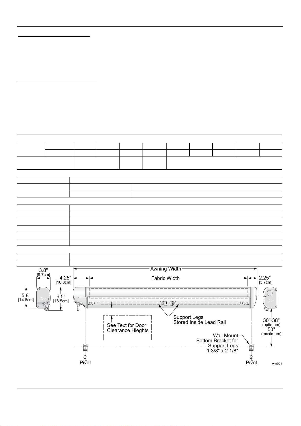
6. When installed, the bottom of the awning case is 13.3cm [5 1/4”] from the centerline of the awning
rail. The rail must be mounted a minimum of 41.3cm [16.25”] above openings to avoid interference.
NOTE: Height dimension is based on clearance over a 76cm [30"] door extension. The
mounting height will vary 1.9cm [.75"] for every 5cm [2"] change in extension. For longer
extensions, add the calculated difference. For shorter extensions, subtract the difference.
7. The centerline of the awning fabric is offset from the centerline of the awning assembly. To align the
center of the fabric, use the backplate of the awning assembly for measurements.
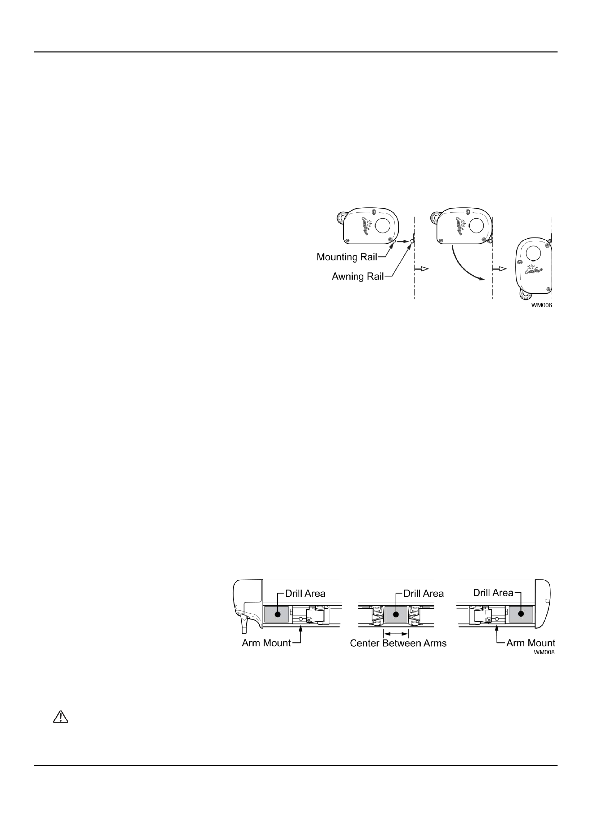
7.1. Lightly spray the inside track of the awning rail
with a silicone lubricant.
7.2. Using a minimum of two people, lift the awning
up and tilt as shown.
7.3. Hook the mounting rail into the awning rail and
roll down.
7.4. Adjust the position of the awning horizontally as required. It may be necessary to lift the awning so
that it will slide in the awning rail.
7.5. For the motorized awning only: xLift the awning upward slightly. On the coach wall, mark the
location of where the motor wires exit the awning case.
xMeasure and drill one 8mm hole through the outer wall at the mark.
NOTES: Adjust the location as required. Measure to avoid any interior framing, cabinets,
electrical components etc. that could be damaged or interfere with the hole location.
Ensure that the motor cables are accessible after routing in the next step.
This is a preliminary step, the wire and switch installation are completed after the awning is
secured.
xRoute the motor wires through the hole and seal with silicone sealant.
10. Rotate the awning down.
11. Open the awning 14"-18" [35 - 45cm] to allow access to the back plate.
NOTE: To open the motorized awning, momentarily connect the motor wires to a 9-14VDC drill
battery or car battery. If the motor runs in the reverse direction, reverse the leads.
12. Drill three (3) 3/16" [4.8mm] holes
through the back of the case into
the mounting surface and into the
structure. Use care to not drill
through the inner wall.
13. In the awning case, ream out the 3/16" [4.8mm] holes to 5/16" [8mm]. Do not allow the drill to extend
into the wall.
CAUTION The screws must be located in the open areas of the awning case as shown. The
arms cannot close completely if the screw heads are underneath.
14. Secure the awning using three (3) #14 x 1 1/2" lag screws.

FREEDOM WM Installation Manual Carefree of Colorado
6 052563-001r9
BOTTOM BRACKET INSTALLATION
The awning is equipped with vertical supports. These supports extend from the leading edge of the awning
to a bracket mounted on the wall or may be used in a carport position on the ground.
1. Determine the location of the brackets:
xClose the awning if open. xMeasure out .5" [1.2cm] from the edge of the lead rail. xAt the marks made
previously, measure down vertically and mark the location of the brackets. The ideal location is 37"-50"
[94-127 cm] below the bottom of the awning.
5/32" [4mm] Pilot Hole
Bottom Bracket
#10 x 3/4"
Flat Head Screws
Pivot Pivot WM009
2. Center the brackets on the marks and using the bracket as a template, drill two (2) 4mm [5/32"] pilot
holes.
3. Attach the brackets with two (2) #10 x 3/4": flat head screws.
MANUAL CRANK HANDLE STORAGE CLIPS
Two clips are provided to store the manual crank handle. These may be mounted horizontally or vertically.
The clips are designed so that one side has a smaller diameter to fit the smaller tube of the handle. The
other side has a larger diameter to fit the larger tube of the handle. The clips can be arranged as shown or
the clips can be oriented so both attach to the larger tube (i.e. if the handle is fully collapsed for storage).
1. Snap the clips on to the crank handle.
2. Position the handle in the desired location and mark the locations of the clips.
3. Remove the clips from the crank handle and mount at the marks made previously. Use the #8 x 1 1/4”
screws provided.
NOTE: The screws will go through the mounting surface approximately 1/2”; if the mounting surface
material is thinner than 1/2” the screws will protrude through the opposite side.

Carefree Installation Manual FREEDOM WM
052563-001r9 7
This completes the installation of the manual awning. For motorized awnings go to "Switch
Installation" on page 7.
SWITCH INSTALLATION (MOTORIZED AWNINGS ONLY)
CAUTION Disconnect the battery and electrical sources before working with the electrical
wiring.
1. Determine the location for the switch.
xThere is approximately 180cm [70"] of wire from the awning motor. If the distance to the switch
exceeds the furnished wire, the installer must furnish 18 awg wire and butt splice to the motor wires.
xLocation should provide the operator a view of the awning during operation.
xThe switch requires a 4.8cm x 7.3cm [1 7/8" x 2 7/8"] area on the mounting surface and a minimum
clearance depth of 3.2cm [1.25"] from the mounting surface.
1. At the switch location, cut a rectangular hole 1.25”(3.2cm) x 1.88” (4.8cm) through the mounting surface.
SK002a
2. Determine the switch orientation:
2.1. The wires of the connector extend from the side of the switch with 3 terminals on the back.
2.2. For wire routing on the right side of the switch, orient the switch with the 3 terminals on the right.
2.3. For wire routing on the left side of the switch, orient the switch with the 3 terminals on the left.
2.4. Push the switch into the faceplate until the tabs on the switch “click” into place behind the faceplate.
Ensure that the switch and faceplate are oriented so that the lettering isup and the wires are oriented
as desired.
2.5. Set switch aside.
3. Route the awning motor wires through the switch hole and attach to the switch connector:
CONNECTOR
WIRE COLOR
LH CONNECTOR ORIENTATION
RH CONNECTOR ORIENTATION
RED→
+12VDC
+12VDC
WHITE→
BLUE (motor wire)
BROWN (motor wire)
BLUE→
BROWN (motor wire)
BLUE (motor wire)
BLACK→
Ground
Ground
4. Run a minimum 14 awg wire from the power distribution panel (auxiliary battery circuit) or equivalent.
The circuit should be protected by a 15-amp fuse.
5. Run a minimum 14 awg wire to system ground.
SK003a
To Ground
To +12VDC
BROWN Motor Wire
BLUE Motor Wire
RED
BLACK
WHITE
BLUE
SK003b
To Ground
To +12VDC
BROWN Motor Wire
BLUE Motor Wire
RED
BLACK
WHITE
BLUE

FREEDOM WM Installation Manual Carefree of Colorado
8 052563-001r9
NOTE: If the wire run is 30 feet or longer, use 12awg wire to prevent voltage drop.
6. Route the two wires through the mounting hole. Butt splice the 12VDC wire to the RED connector wire.
Butt splice the ground wire to the BLACK connector wire.
7. Attach the connector to the switch.
8. Restore power and test the switch operation.
9. If the awning operates opposite to the switch plate markings:
xShut off power; xReverse motor wires connected to the blue and
white connector wires; xRestore power and test.
10. Push the wires, connector and switch into the mounting hole and secure the switch plate. Use two (2)
#6 x 3/4" flat head screws.
OPTIONAL LED LIGHTING
Optional LED lighting may be mounted in the lead rail. The wiring runs along the top of the arm.
For motorized awnings: Route the LED wire harness with the motor cable.
For manual crank awnings: The harness routes through the end of the case. Drill a 3/16" hole into the
vehicle wall as shown on page 4.
CAUTIONS:
The wire should be secured to the wall of the vehicle where it is exposed on the outside of the vehicle.
Use a quality silicone sealant/adhesive.
Do not route the wire over sharp edges or heat sources that can cut or fray the wires or wire insulation.
Damage that is a result of improper routing may void warranty.
SWITCH INSTALLATION
NOTE: Installers may choose to furnish the control switch. The installation requires that the power line
(+12VDC) be attached to a dedicated 2A circuit breaker or a 2A in-line fuse must be installed between the
switch and power source. For easy access, locate the fuse close to the switch.

Carefree Installation Manual FREEDOM WM
052563-001r9 9
1. Determine the location of the switch.
2. At the switch location, cut a 1 1/8" x 1
1/2" hole.
3. Wire the switch as shown below. Wire
terminals at the switch are .187, 18-24
awg female disconnects.
NOTE: Allow adequate slack in the
12VDC power line so that the in-line
fuse (installed in step 4) can be
accessed from behind the switch.
4. Install the in-line fuse:
4.1. Near the switch, cut the red
12VDC power line to the switch. Do
not strip the insulation.
4.2. Insert a wire end into one of
the wire channels until it butts up
against the stop.
4.3. Fold that half of the
connector body over until the
element contacts the wire. Use
pliers to crimp the connector closed.
4.4. Repeat for the second wire
end.
4.5. Slide the fuse into the fuse
port. Ensure that it is firmly seated.
5. Press the in-line fuse, wires and switch
into the mounting hole. Secure the
switch using two (2) #6 x 1/2" screws.
6. Snap the switch bezel over the switch
frame. LED002c
PITCH ADJUSTMENT
The Freedom WM provides minor pitch adjustment for aligning the lead rail with the case. This adjustment
is only for fine-tuning the installation. It is not intended as an operational pitch adjustment.
CAUTION When the pitch of the awning is adjusted, it is important that the lead rail is parallel to
the awning housing.
1. Open the awning to access the adjustment screw located on
the arm case knuckle.
2. Have a second person lift up on the lead rail to relieve the
pressure on the adjustment screw.
3. Using a 5mm allen wrench, turn the adjustment screw Arm
Case Knuckle Pitch Adjustment Screw
clockwise to raise the lead rail; turn the adjustment screw WM013 counterclockwise to lower the lead rail.
Figure 1. Pitch Adjustment.
4. Repeat for the other side as necessary.

FREEDOM WM Installation Manual Carefree of Colorado
10 052563-001r9
MANUAL OVERRIDE (MOTORIZED VERSIONS ONLY)
If power to the vehicle is not available, the awning can be safely retracted
using the manual override located on the idler (right) end of the case.
NOTE: This procedure cannot be used to extend the awning.
1. Remove the plug from the right endcap and save.
2. Insert a 3/8" socket drive extension and handle into the square drive
hole inside the end cap.
3. Turn the handle counterclockwise until the awning is retracted.
4. Replace the plug.
CAUTION After closing the awning with the manual override, the lead rail may move out from the case
1/4" 1/2". This is normal and the awning is secure for travel until power is restored or repairs are completed.
Do not attempt to force the lead rail in with the override, serious damage can occur to the awning.
SETTING THE MOTOR LIMITS
The motor limit switches are preset at the factory for best operation of the awning. It may be necessary to
reset the switches. The “OUT” limit switch is used to stop the motor when the awning is fully extended. The
“IN” limit switch is used to stop the motor when the awning is fully retracted.
The limit switches are located inside the motor endcap.
Figure 2. Motor Limit Switches.
To access the switches, remove the outer motor endcap and plug.
Adjusting the OUT Limit Switch
1. Extend the awning out completely.
2. Confirm that the arms are fully extended. The motor should stop and the fabric should be tight. If the
motor continues to run, the fabric will sag; or, if the motor quits before the arms are extended, it will be
necessary to adjust the “OUT” limit switch.
3. Using a 4mm Allen wrench turn the “OUT” limit switch. CLOCKWISE increases time the motor runs during
extension, COUNTERCLOCKWISE reduces the time the motor runs.
NOTE: It is best to make the adjustments in increments of a single turn. 3 full turns of the screw
equals approximately 2” of fabric extension.
4. Extend and retract the awning several times to confirm that the adjustment is correct.
5. Repeat steps 3 and 4 as required until the awning extends correctly.

Carefree Installation Manual FREEDOM WM
052563-001r9 11
Adjusting the IN Limit Switch
1. Retract the awning in completely.
2. Confirm that the arms are fully retracted. The motor should stop when the awning is fully retracted. If
the motor quits before the arms are fully retracted, it will be necessary to adjust the “IN” limit switch.
3. Using a 4mm Allen wrench turn the “IN” limit switch. Clockwise increase time the motor runs during
retraction, counter clockwise reduces the time the motor runs.
NOTE: It is best to make the adjustments in increments of a single turn. 3 full turns of the screw
equals approximately 2” of fabric extension.
4. Extend and retract the awning several times to confirm that the adjustment is correct.
5. Repeat steps 3 and 4 as required until the awning retracts correctly.
Table of contents
Other Carefree Automobile Accessories manuals

Carefree
Carefree FREEDOM FREESTYLE WM User manual

Carefree
Carefree Awning Stabilizer Pole Kit HD User manual

Carefree
Carefree LATITUDE User manual

Carefree
Carefree FREEDOM FREESTYLE WM User manual

Carefree
Carefree SUMMIT User manual

Carefree
Carefree MARQUEE User manual

Carefree
Carefree DIRECT RESPONSE User manual

Carefree
Carefree ASCENT SS User manual

Carefree
Carefree Freestyle RM User manual

Carefree
Carefree MIRAGE User manual