Carefree SR0023 User manual

052987-002R5 Printed in USA July 2005
CAREFREE
WIND SMART AUTO-RETRACT SYSTEM
RV INSTALLATION &OPERATIONS MANUAL
THIS PUBLICATION COVERS THE FOLLOWING OPTIONAL EQUIPMENT KITS:
SR0023, SR0032 - Wind Smart Upgrade - Eclipse
SR0013 Wind Smart Upgrade – One Touch
SR0014 – Remote Control Upgrade – Wind Smart
TABLE OF CONTENTS
Introduction ...................................................................................................................................2
Product Overview ...................................................................................................................................2
Safety Information...................................................................................................................................2
Safety Notes...................................................................................................................................2
Installation .....................................................................................................................................3
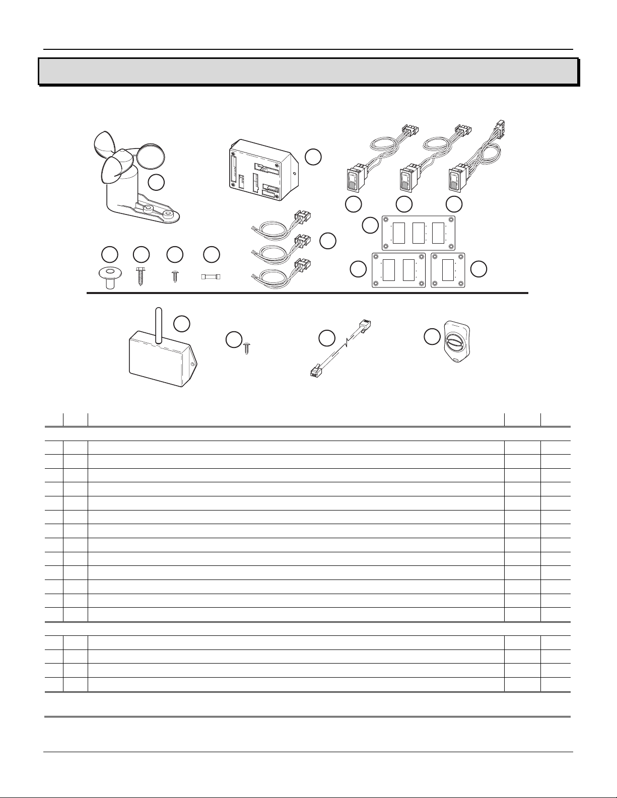
Components Checklist............................................................................................................................3
Prior to Installing the Kit..........................................................................................................................4
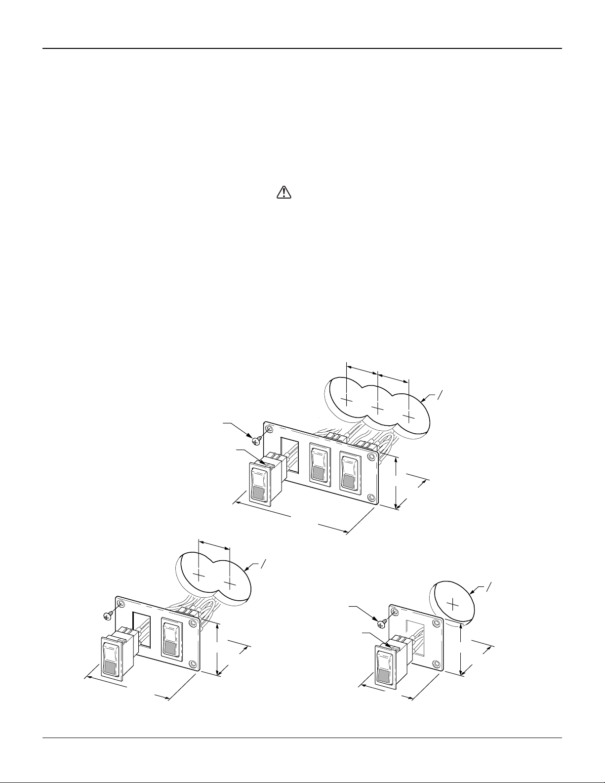
Installing the Switches ............................................................................................................................5
Wiring an Additional Patio Switch...................................................................................................6
Installing the Wind Smart Control Box....................................................................................................6
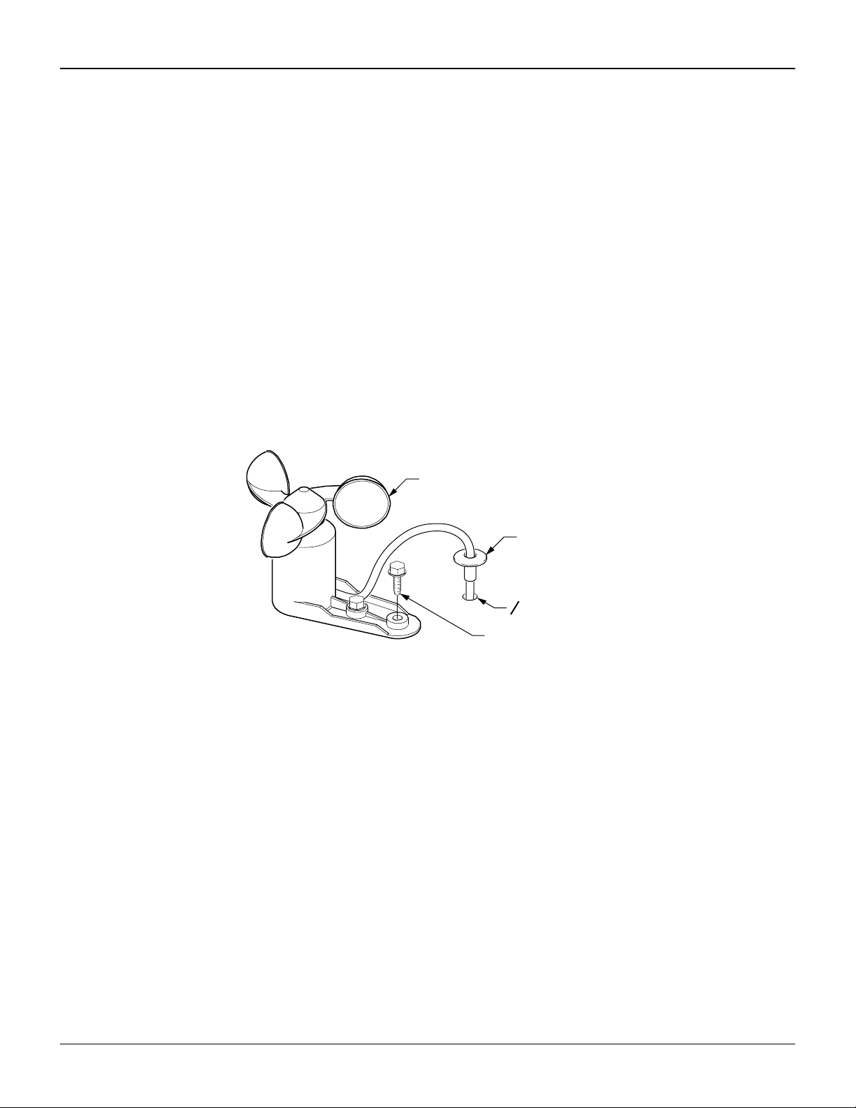
Installing the Anemometer ......................................................................................................................7
Testing the System .......................................................................................................................8
Testing Standard Operation....................................................................................................................8
Testing Wind Smart Operation ...............................................................................................................9
Installing the RR24 RF Remote Receiver ..................................................................................10
Programming the RR24 for the Key FOB .............................................................................................11
Testing the Key FOB ............................................................................................................................11
Diagnostics..................................................................................................................................12
System Schematic ................................................................................................................................16
Operating the Wind Smart System ............................................................................................17
The Basics............................................................................................................................................17
Mode Switch.................................................................................................................................17
Patio Switch..................................................................................................................................17
The Wind Smart Auto-Retract System..................................................................................................17
Sensitivity Switch..........................................................................................................................17
Using the Key FOB Remote Control.....................................................................................................18
Limited Warranty.........................................................................................................................19
Carefree of Colorado 2145 W. 6
th
Avenue Broomfield, CO 80020
aScott Fetzer company 303-469-3324 ♦www.carefreeofcolorado.com

Carefree of Colorado Wind Smart Auto-Retract System
2 052987-002R5
INTRODUCTION
PRODUCT OVERVIEW
The Wind Smart Auto-Retract System may be installed as part of the original motorized awning installation
or as an upgrade to an existing motorized awning installation. In addition, an optional RF wireless remote
may be included at time of installation or added after the installation.
The system offers three unique features not available with a standard awning installation.
1) Auto-Retract – When the awning is retracted, it retracts completely. It is not necessary to hold the
button when closing the awning.
2) Wind Smart – The awning can be set to automatically close when windy conditions occur.
3) Remote Control – The operator can conveniently operate the awning from any location.
SAFETY INFORMATION
WARNING
AWARNING INDICATES A POTENTIALLY HAZARDOUS SITUATION WHICH ,IF NOT AVOIDED,COULD RESULT IN
DEATH OR SERIOUS INJURY AND/OR MAJOR PROPERTY DAMAGE.
CAUTION
ACAUTION INDICATES A POTENTIALLY HAZARDOUS SITUATION THAT MAY CAUSE MINOR TO
MODERATE PERSONAL INJURY AND/OR PROPERTY DAMAGE.IT MAY ALSO BE USED TO ALERT
AGAINST UNSAFE PRACTICES.
NOTE: A note indicates further information about a product, part, or step.
Tip: A tip provides helpful suggestions.
Safety Notes
•Always disconnect battery or power source before working on or around the electrical system.
•Always wear appropriate safety equipment (i.e. goggles).
•Always use appropriate lifting devices and/or helpers when lifting or holding heavy objects.
Table of Contents

Carefree of Colorado Wind Smart Auto-Retract System
3 052987-002R5
INSTALLATION
COMPONENTS CHECKLIST
Carefree of Colorado
PATIO WIND SPEED MODE
AUTO
RETRACT
ON
OFF
POWER
ON
HI
MED
LOW
RETRACT
EXTEND
WIND SPEED
Carefree of Colorado
HI
MED
LOW
Carefree of Colorado
PATIO MODE
AUTO
RETRACT
ON
OFF
POWER
ON
RETRACT
EXTEND
2
1
3 4 5
96
78
12 11 10
14 15 16 17
Wind Smart Kit
Remote Control Kit (ordered seperately)
13
WS001
Figure 1. Component Checklist.
;ITEM DESCRIPTION QTY NOTE
WIND SMART KIT
1 Anemometer 1
2 RP24 Control Unit 1
3 Switch, Patio, Momentary Contact 1
4 Switch, Wind Speed, Latching, w/o Light 1
5 Switch, Mode, Latching, w/ Light 1
6 Switch Plate, 3 Switch 1
7 Switch Plate, Patio/Mode 1
8 Switch Plate, Wind Speed 1
9 Harness, Power, Motor, Anemometer 3
10 Wire Splice, 14-16GA. 6
11 Screw, Phillips Truss Head #6 x 1/2 10
12 Screw, Hex Head #10 x 3/4 2
13 Grommet, Wall 1
REMOTE CONTROL KIT ORDERED SEPARATEL
Y
14 RR24 Receiver, RF 1
15 Screw, Phillips Truss Head #6 x 1/2 2
16 Cable 60” 1
17 Remote Control Key Fob 1 1
NOTES:
1. Additional remote control Key FOBs may be ordered separately.
Table of Contents

Carefree of Colorado Wind Smart Auto-Retract System
4 052987-002R5
PRIOR TO INSTALLING THE KIT
For New Installations – These instructions assume that the awning and arms have been mounted and that the
cable(s) from the arms have been routed through the exterior wall as described in the awning installation
instructions. These instructions replace the switch and wiring directions included with the awning.
For Existing Installations – The installer must locate and remove any existing control boxes and switches (not
including the exterior switch with the Eclipse). Access to the motor cable(s) and the 12VDC/Ground wires is
required.
There are three (3) switch plate configurations available for this installation.
A) Three switch plate (this should be used unless the plate does not fit in the desired location).
B) Two switch plate plus a single switch plate (this option is used when it is necessary to “stack” the
switches because of space limitations)
C) Two switch plate (this is used because of space restrictions). This configuration eliminates the “Wind
Speed Switch”. When the wind speed switch is not used, the system defaults to the “medium” setting.
1. Determine the location of the switches and control box:
1.1 Do not mount the control box and switches near heat producing elements such as LP appliances
or engine exhaust components.
1.2 The mounting surface for the switch plate should be a minimum of 1/2” thick.
1.3 The clearance dimensions for the switch plates are shown in Figure 2 on page 5.
1.4 Mount the control box near the switch panel so that the switch harnesses can be plugged into the
control box without stressing the connections. Clearance dimensions are shown in Figure 3 on
page 6.
2. Determine the location of the anemometer:
2.1 Position the anemometer in a location that is not blocked from the wind. Suitable positions would
be along the roofline or on the roof.
2.2 Approximately 6 foot of cable is furnished with the anemometer. It is the installer’s responsibility
to provide additional cable and splices if the anemometer is mounted a greater distance from the
control box.
2.3 For the Eclipse and One-Touch, the anemometer cannot be mounted on the case of the awning.
3. Determine the location of the optional RF receiver (RR24):
3.1 Do not mount the RR24 unit near heat producing elements such as LP appliances or engine
exhaust components.
3.2 For best reception, do not mount the RR24 near or on a metal surface.
3.3 Mount the unit with the antenna pointing up.
3.4 The clearance dimensions for the RR24 are shown in Figure 6 on page 10.
3.5 The included cable is approximately 60 inches long. Mount the unit close enough to the control
box so that the cord can be connected without stressing the connections.
CAUTION
ALWAYS DISCONNECT THE VEHICLE BATTERY AND ELECTRICAL SOURCES BEFORE WORKING WITH
THE ELECTRICAL WIRING AND COMPONENTS.
When the WindSmart installation is complete, return to the original awning instructions for any final
assembly required.
Table of Contents

Carefree of Colorado Wind Smart Auto-Retract System
5 052987-002R5
INSTALLING THE SWITCHES
(refer to Figure 2)
1. At the switch panel location(s), use a 2 1/4” hole saw and cut one hole for each switch. The center of
each hole is 1 1/2” apart for switches mounted in the same panel.
2. Each switch assembly is labeled. Carefully push the connector and wires through the switch panel
then push the switch into the faceplate until the locking tabs click into place behind the faceplate.
•The momentary switch is the “Patio” switch;
•The latching switch w/o light is the “Wind Speed” switch;
•The latching switch w/ light is the “Mode” switch.
CAUTION
ENSURE THAT THE SWITCH LABELS MATCH THE FACEPLATE LABELS FOR THE SWITCH IDENTIFICATION
AND ORIENTATION!THE SQUARE LENS ON THE SWITCH MUST BE AT THE BOTTOM.
NOTE: If it is necessary to remove the switch from the panel, press and hold the locking tabs
on the switch then carefully work the switch out of the panel. Do not try to force the
switch, it is possible to break the locking tabs.
3. After all switches are mounted into the faceplate(s), carefully push the connectors, wires and switches
into the mounting holes drilled in step 1.
4. Hold the faceplate(s) in position and secure to the mounting surface using four (4) #6 x 1/2 screws.
Tip: Drilling a small pilot hole for the screws will reduce the chance of splitting or stripping out the
hole with the screws.
5 3/4”
2 3/4”
2 3/4”
O 2 1/4”
1 1/2” 1 1/2”
Patio / Sensitivity / Mode Switches
4 1/4”
2 3/4”
2 3/4”
O 2 1/4”
1 1/2”
Patio / Mode Switches 2 3/4”
2 3/4”
2 3/4”
O 2 1/4”
Sensitivity Switch WS002
#6 x 1/2 Screw
(typ.)
#6 x 1/2 Screw
(typ.)
Locking Tab
(ref)
Locking Tab
(ref)
Figure 2. Mounting the Switches.
Table of Contents

Carefree of Colorado Wind Smart Auto-Retract System
6 052987-002R5
Wiring an Additional Patio Switch
This section is for wiring an additional PATIO switch and for Eclipse models with an exterior switch.
(refer to the schematic on page 16)
1. Route the switch wires to the main switch location.
2. Splice the wires in parallel with the main PATIO switch wires. Pin 1 of the additional switch should go
to pin 1 of the main patio switch etc.
INSTALLING THE WIND SMART CONTROL BOX
1. Position the control box and secure using two (2) #6 x 1/2” screws.
NOTE: If the box is mounted on a surface that is less that 1/2” thick, the screws will protrude
through the opposite side of the surface.
2. Attach the switch harness connectors to the box at the positions labeled on the box. Press the
connectors in until the tabs click into place to ensure a solid connection.
3. Run a 12 gauge wire (never use less than 14 gauge) from the power distribution panel (auxiliary
battery circuit) or equivalent.
4. Run a wire to chassis ground. Suitable ground would be the vehicle chassis or conductive structure
connected to the chassis.
5. Connect a two-wire harness to the control box in the position marked +12V/GROUND.
6. Splice the wires from steps 2 and 3 to the harness. Carefully note the labeling on the box so that the
12V power goes to the 12V pin and the ground goes to the pin labeled ground.
7. Connect a two-wire harness to the control box in the position marked MOTOR.
8. Run the motor wire cable from the awning to the control box. Splice the wires to the harness in step
7. The red wire should go to Pin marked “A” and the black goes to the pin marked “B”.
NOTE: During testing, it may be necessary to reverse these wires (red to B, black to A) if the
awning extend and retract functions are reversed.
ANEMOMETER
PATIO SWITCH
WIND SPEED
SWITCH
RR24
(Optional)
MODE SWITCH
AB
MOTOR
FUSE (15 A)
+12V
GROUND
5 1/4” 2”
3 1/8”
15
Figure 3. Mounting the Wind Smart Control Box.
Table of Contents

Carefree of Colorado Wind Smart Auto-Retract System
7 052987-002R5
INSTALLING THE ANEMOMETER
NOTE: Whenever drilling and mounting on the outside wall or roof, be aware of internal cabinet
framing or other structure that may be behind the outer surface. Adjust drill locations as
necessary to prevent unnecessary damage. Interior structure and components could also
interfere with drilling and cable routing.
(refer to Figure 4)
1. Position the anemometer in location and mount using two (2) #10 x 3/4 screws.
•Align the screw holes with a roof support;
•For rubber roofs, do not drill pilot holes for the mounting screws;
•For fiberglass roofs, drill two pilot holes using the anemometer as a template.
•Coat the bottom of the anemometer with silicone sealant. With particular attention around the
mounting holes.
2. Drill a 7/16” hole in the sidewall or roof, close to the anemometer.
3. Slide the cable through the grommet and into the hole drilled in step 2.
4. Coat the underside of the grommet flange with a silicone sealant; then seat the grommet in the hole.
5. Push the wire through the grommet for best fit then seal the wire in the grommet with silicone sealant.
Grommet
O 7/16”
#10 x 3/4 Screw (2)
Anemometer
Figure 4. Mounting the Anemometer.
6. Route the cable to the control box.
7. (refer to Figure 3) Connect the last two-wire harness to the control box in the position marked
ANEMOMETER.
8. Splice the two wires from the anemometer to the harness. The wires are not pin specific.
9. Go to
Testing the System on page 8 before installing the RF remote option.
Table of Contents

Carefree of Colorado Wind Smart Auto-Retract System
8 052987-002R5
TESTING THE SYSTEM
Ensure that the operator can see the awning during the tests or has a helper that can see the awning.
Definitions: Manual – the motor runs only while the switch is pressed.
Automatic – the motor continues to run after the button is released.
Carefree of Colorado
PATIO WIND SPEED MODE
AUTO
RETRACT
ON
OFF
POWER
ON
HI
MED
LOW
RETRACT
EXTEND
WS008a
Figure 5. Control Switches.
TESTING STANDARD OPERATION CAUTION
THE RETRACT FUNCTION IS AUTOMATIC AND WILL CONTINUE UNTIL THE AWNING IS FULLY
RETRACTED.ENSURE THAT DURING TESTING AND OPERATION,NO OBTACLES OR PEOPLE ARE IN
THE WAY OF THE AWNING.
NOTE: For the Eclipse, the extend function is automatic. For One-Touch, the extend function is
manual. For testing the One-Touch, the operator must press and HOLD the extend switch.
1. Turn the MODE switch to the OFF position and restore vehicle power.
2. Press and release the PATIO switch in the EXTEND position. The awning should not move.
3. Press and release the PATIO switch in the RETRACT position. The awning should not move.
4. Turn the Mode switch to the POWER ON position.
5. Press and release the PATIO switch in the EXTEND position. The awning should extend
automatically. Allow the awning to extend for 2-3 seconds then press and release the PATIO switch a
second time to stop the awning.
STOP: If the awning does not move or functions differently than described above, set the Mode
switch to the off position. Go to the Diagnostics section on page 12. Restart the tests after
following the steps in the Troubleshooting section.
6. Press and release the PATIO switch in the RETRACT position. The awning should retract
automatically. Allow the awning to retract for 2-3 seconds then press and release the PATIO switch a
second time to stop the awning.
STOP: If the awning does not move or functions differently than described above, set the Mode
switch to the off position. Go to the Diagnostics section on page 12. Restart the tests after
following the steps in the Troubleshooting section.
7. Press and release the PATIO switch in the RETRACT position. The awning should retract
automatically until it is completely closed. The motor should stop when the awning is fully retracted.
8. Carefully secure the anemometer so that the cups cannot spin during the next tests.
9. Turn the Mode switch to the WIND SMART ON position.
10. Repeat steps 5 through 7.
Table of Contents

Carefree of Colorado Wind Smart Auto-Retract System
9 052987-002R5
TESTING WIND SMART OPERATION
NOTE: These tests will use the WIND SPEED switch.
HI is the least sensitive and responds to winds approximately equal to 12 mph.
MEDIUM responds to winds approximately equal to 8mph.
LOW is the most sensitive and responds to winds approximately equal to 4mph.
1. If not previously done, release the anemometer (step 7 above).
2. Set the MODE switch to WIND SMART ON.
3. Set the
WIND SPEED switch to HI.
4. Extend the awning using the PATIO switch.
5. Spin the anemometer. The awning should retract automatically to the closed position.
NOTE: Do not hit the anemometer to spin. Using compressed air provides a constant pressure
source and, the output can be regulated to test the various sensitivity settings. DO NOT
position the nozzle closer than 10 inches from the cups.
STOP: If the awning does not move or functions differently than described above, set the Mode
switch to the off position. Go to the Diagnostics section on page 12. Restart the tests after
following the steps in the Troubleshooting section.
6. Repeat steps 3 and 4 two (2) more times with the Wind Speed switch set to MED and then to LOW.
7. Repeat steps 2 through 4 with the Mode switch set to OFF and POWER ON. The awning should not move.
Table of Contents

Carefree of Colorado Wind Smart Auto-Retract System
10 052987-002R5
INSTALLING THE RR24 RF REMOTE RECEIVER
1. Determine the location of the optional RF receiver (RR24):
1.1 Do not mount the RR24 unit near heat producing elements such as LP appliances or engine
exhaust components.
1.2 For best reception, do not mount the RR24 near or on a metal surface.
1.3 Mount the unit with the antenna pointing up.
1.4 The clearance dimensions for the RR24 are shown in Figure 6 on page 10
1.5 The included cable is approximately 60 inches long. Mount the unit close enough to the control
box so that the cord can be connected without stressing the connections.
1.6 Allow adequate room below the box to access the connector jack, programming button and
indicator light.
2. Position the control box and secure using two (2) #6 x 1/2” screws.
NOTE: If the box is mounted on a surface that is less that 1/2” thick, the screws will protrude
through the opposite side of the surface.
3. Connect the cable to the RR24.
4. Route the cable to the Wind Smart control box and connect.
3 7/8”
4 3/16”
TO
EYE PORT
on RP24
Program
Mode
Press to Learn
Transmitter
UP
RR24
1”
Program
Button
Indicator
Light
Key FOB
WS005
Figure 6. Mounting the RF Receiver.
Table of Contents

Carefree of Colorado Wind Smart Auto-Retract System
11 052987-002R5
PROGRAMMING THE RR24 FOR THE KEY FOB
1. Power to the Wind Smart control box must be on.
2. Press and release the “Press to Learn Transmitter” button on the bottom of the RR24 box. The
receiver is in program mode when the red light comes on.
3. Press and release the CENTER button on the Key FOB. The red light will go out after the RR24 learns
the Key FOB signal.
4. Repeat steps 2 and 3 for each additional Key FOB.
OPERATIONAL NOTES:
•The RR24 exits the program mode after ten seconds.
•If the light does not come on in step 2, check the continuity of the cord between the boxes and
repair or replace as required. Pin 1 of the 1st connector goes to pin 1 of the 2nd connector etc. If
the light still does not come on, the memory is full and must be cleared.
•If the light does not go out in step 3, the RR24 knows the Key FOB signal or the battery in the
FOB needs to be replaced.
•To clear the RR24 memory, press and hold the program button for 5 seconds.
•The RR24 may be programmed for up to 5 Key FOBs. Additional Key FOBs may be ordered
separately.
TESTING THE KEY FOB
Prior to testing the remote control Key FOB, the Wind Smart system must be fully installed, tested and operational.
If the system has not been tested, go to “Testing the System” on page 8 before continuing this section.
1. Ensure that power is on to the Wind Smart control box.
2. Extend the awning out about half way.
3. Set the MODE switch to “OFF”.
4. Press each button on the Key FOB. The awning should not
move.
5. Set the MODE switch to “POWER ON”.
6. Press and hold the EXTEND button on the Key FOB for 2 to 3
seconds; then release the button. The awning should extend
out until the button is released
7. Press and release the RETRACT button on the Key FOB. The awning should retract automatically.
CAUTION
THE RETRACT FUNCTION IS AUTOMATIC AND WILL CONTINUE UNTIL THE AWNING IS FULLY
RETRACTED.ENSURE THAT DURING TESTING AND OPERATION,NO OBTACLES OR PEOPLE ARE IN
THE WAY OF THE AWNING.
8. While the awning is retracting, press and release the STOP (center) button on the Key FOB. The
awning should stop when the button is pushed.
NOTE: The retract function will also stop if the extend or retract buttons are pushed once.
9. Set the MODE switch to “WIND SMART ON”.
10. Repeat steps 6 through 9.
11. If the Key FOB does not operate as described previously, use diagnostics “D08 Awning Does Not
Move When Key FOB Buttons Are Pushed” on page 15.
Key FOB
MODE
AUTO
RETRACT
ON
OFF
POWER
ON
WS007a
Figure 7. Key FOB Test.
Table of Contents

Carefree of Colorado Wind Smart Auto-Retract System
12 052987-002R5
DIAGNOSTICS
The following procedures are intended to aid the installer and service technician to logically resolve operational
issues with the Wind Smart installation. These procedures do not address conditions that may arise with the basic
awning installation. For awning related concerns, refer to the appropriate awning manual.
Procedures in this section: Page
D01 THE AWNING DOES NOT EXTEND AND/OR RETRACT USING THE PATIO SWITCH......12
D02 THE AWNING OPERATES IN REVERSE OF THE SWITCH PLATE LABEL .....................12
D03 THE AWNING AUTO-EXTENDS WHEN THE RETRACT SWITCH PUSHED .....................12
D04 THE AWNING AUTO-EXTENDS AND MANUALLY RETRACTS .....................................12
D05 AWNING DOES NOT AUTO-RETRACT DURING WINDY CONDITIONS .........................13
D06 TESTING A SWITCH AND HARNESS.........................................................................13
D07 TESTING THE CONTROL BOX.................................................................................14
D08 AWNING DOES NOT MOVE WHEN KEY FOB BUTTONS ARE PUSHED......................15
In the charts below, YES is a positive response to the test; NO is a negative response.
D01 THE AWNING DOES NOT EXTEND AND/OR RETRACT USING THE PATIO SWITCH
The Mode switch must be in the POWER ON or WIND SMART ON positions.
A Confirm Power Supply
YES Go to test B
Is vehicle battery or power source providing 10V to 14V to the
control box. NO Correct as required
YES Switch and harness OK; go to test C
B Confirm Operation of MODE Switch
Use test procedure “D06 Testing a Switch and Harness” NO Repair or replace as recommended
in procedure and retest
YES Switch and harness OK; go to test D
C Confirm Operation of PATIO Switch
Use test procedure “D06 Testing a Switch and Harness” NO Repair or replace as recommended
in procedure and retest
YES Control box OK; refer to awning’s
troubleshooting guide
D Is the control box operating correctly?
Use procedure “D07 Testing the Control Box”
NO Repair as recommended in
procedure and retest
D02 The Awning Operates In Reverse of the Switch Plate Labeling
The Mode switch must be in the POWER ON or WIND SMART ON positions.
YES Switch and Harness OK; go to test B
A Confirm Operation of PATIO Switch
Use test procedure “D06 Testing a Switch and Harness” NO Repair or replace as recommended
in procedure and retest
YES Power and Control Box OK
B Is the control box operating correctly?
Use test procedure “D07 Testing the Control Box” NO Repair as recommended in
procedure and retest
D03 THE AWNING AUTO-EXTENDS WHEN THE RETRACT SWITCH PUSHED
The Mode switch must be in the POWER ON or WIND SMART ON positions.
YES Test OK
A Reverse motor leads at control box and retest
NO Reanalyze condition
D04 The Awning Auto-Extends and Manually Retracts
The Mode switch must be in the POWER ON or WIND SMART ON positions.
YES Test OK
1. Reverse motor leads at control box
2. Check that switch is oriented correctly in plate – correct as
required (refer to DO6-A and DO6-B)
NO Reanalyze condition
Table of Contents

Carefree of Colorado Wind Smart Auto-Retract System
13 052987-002R5
D05 AWNING DOES NOT AUTO-RETRACT DURING WINDY CONDITIONS
NOTE: The mode switch must be set to “Wind Smart ON”
YES Function works using the switch; go
to test B
A Confirm that the retract function works using the PATIO switch
NO Function does not work with switch;
go to procedure D01 on page 12
B Test Anemometer
YES Go to step B2
1 Do the anemometer cups spin freely?
NO Anemometer defective - replace
YES Plug the connector into the control
box;
Go to “Testing The Control Box”
2 Test signal from anemometer:
2.1 Remove anemometer connector from control box;
2.2 Place continuity tester between pins of connector;
2.3 Have a helper slowly turn the anemometer:
Does the circuit open and close? It should open
and close once for every revolution.
NO The circuit stays open or stays
closed; go to step B3
YES Continuity OK; replace anemometer
3 Test the wire continuity between the connector and the
anemometer. NO Repair or Replace wires as required
D06 TESTING ASWITCH AND HARNESS
Disconnect the switch harness connectors from the control box and remove the plate and switches from the
mounting surface.
YES Switch mounted OK; go to test B
A Confirm Switch is mounted in correct position and correctly
oriented. Refer to Figure 5 on page 8. The lens or lens caps
should be on the bottom of the switch as indicated by the
shaded area.
NO Carefully remove the switch, rotate
180 and reinstall in panel.
Reconnect harnesses and retest
YES Switch wired OK; go to test C
B Confirm switch is wired correctly. Use the schematic and
confirm the wires from the switch to the connector are
correctly placed.
NO Rewire the switch according to the
schematic on page 16
C Test the Switch Function (this test requires a continuity tester)
•Do not remove the wires from the back of the switch. From the numbered terminal of the switch, trace the wire to
the connector; place the tester leads on the connector pins. The pins are not marked on the connector.
•Steps 1 through 5 are for the Patio and Wind Speed Switches. Refer to step 6 for the Mode Switch.
YES Circuits are open, go to step 2.
1 Using a continuity tester, place one lead on common (Pin
3 – Patio; pin 5 – Wind Speed). Place the second lead on
pin 1. Put the switch in the center position and measure
the continuity. Move the second lead to pin 7, measure
the continuity.
Circuit should be open
NO Circuit(s) are closed (continuity
exists); switch assy is defective -
replace
YES Circuit closed; go to step 3
2 Place the second lead on pin 1. Press the switch down
(“Extend” for patio, “Lo” for sensitivity). Is circuit closed? NO Circuit open; switch defective-replace
YES Circuit open; go to step 4
3 Leave the leads in position of step 2. Press the switch up
(“Retract” for patio, “Hi” for sensitivity). Is the circuit open? NO Circuit closed, switch defective-replace
YES Circuit open; go to step 5
4 Move the second lead to pin 7. Press the switch down
(“Extend” for patio, “Lo” for sensitivity). Is the circuit open? NO Circuit closed, switch defective-replace
YES Circuit closed; go to step 6
5 Leave the leads in position of step 4. Press the switch up
(“Retract” for patio, “Hi” for sensitivity). Is the circuit closed? NO Circuit open; switch defective-replace
YES Switch tests OK, return to diagnostic
6 For Mode Switch only – Follow steps 1 through 5 using
pins 5, 2 and 8 respectively NO Test failed; switch defective
1
7
5
3
2
8
6
4
910
Mode
1
7
3
Patio
WS009a
Wind Speed
1
7
5
Table of Contents

Carefree of Colorado Wind Smart Auto-Retract System
14 052987-002R5
D07 TESTING THE CONTROL BOX
This test has been developed as a bench test of the control box.
A Test Power
YES Fuse OK; go to step A2
1 Check Fuse
NO Replace fuse. If the fuse continues
to blow, this may be an indication of a
situation with the power lines to the
control box or with the control box If
so, replace fuse and go to step A2
YES Voltage and Polarity is correct; go to test
B
YES Voltage is correct but polarity is
reversed. Reverse wires and retest.
2 Confirm power to the control box:
2.1 Remove connector to control box
2.2 Test voltage across terminals. Value should be
between 10V and 14V. Polarity must match
symbols on control box. NO Voltage is less than 10V. Check
vehicle power sources and correct as
required. If battery is OK, check wire
continuity to power plug and repair as
required
B Test Control Box Function
For these tests:
•Refer to the schematic on page 16:
•Remove all plugs from the control box except for the power connector.
•Place the positive lead of a voltmeter on pin B (motor) and the negative lead of voltmeter on pin A..
YES Voltage OK; go to step B1.41 Measure the “Power On” Setting
1.1 Place a jumper between pins 6 and 8 (this will
simulate “Power On”.
1.2 Place a second jumper between pins 11 and 12
(this will simulate the “Retract Function”
1.3 Does voltage equal –10V to –14V?
NO Control box is defective - replace
YES Voltage OK; go to step B2
1.4 Move the second jumper between pins 12 and 13
this will simulate the “Extend Function”
1.5 Does voltage equal +10V to +14V? NO Control box is defective - replace
YES Voltage OK; go to step B2.4Measure the “Wind Smart On” Setting
2.1 Place a jumper between pins 7 and 8 (this will
simulate “Wind Smart On”.
2.2 Place a second jumper between pins 11 and 12
(this will simulate the “Retract Function”
2.3 Does voltage equal –10V to –14V?
NO Control box is defective - replace
YES Voltage OK; return to diagnostic
2
2.4 Move the second jumper between pins 12 and 13
this will simulate the “Extend Function”
2.5 Does voltage equal +10V to +14V?
NO Control box is defective - replace
Table of Contents

Carefree of Colorado Wind Smart Auto-Retract System
15 052987-002R5
D08 Awning Does Not Move When Key FOB Buttons Are Pushed
Before continuing, ensure that the Wind Smart system is working correctly. Reference the following sections as
needed: “Operating the Wind Smart System” page 17
“Testing the System” page 8
"Diagnostics” page 12
1. Confirm power to Wind Smart control box -- Correct as required
2. Confirm Mode switch is set to “Power On” or
“Wind Smart On”
-- Correct as required
YES Cable is OK. Confirm that cable is
securely plugged in; go to step 4
3. Check the cable between the RR24 and Windsmart
control box. As a continuity check, Pin 1 of connector 1
goes to Pin 1 of connector 2; pin 2 goes to pin 2; pin 3
goes to pin 3 and pin 4 goes to pin 4
NO Repair or Replace as required.
4. Confirm that the RR24 is programmed for the Key FOB -- Refer to “Programming the RR24 for
the Key FOB” on page 11 and retest.
If system does not work; go to step 5
YES 2nd Key FOB works. Replace battery
in 1st Key FOB and retest, if no
response, 1st Key FOB is defective.
5. Program a second Key FOB and test
NO 2nd Key FOB does not work; go to
step 6
YES System works OK. 1st receiver is
defective
6. Replace the RR24 Receiver and test
NO System does not work. Reinstall 1st
receiver; go to step 7
7. Replace Wind Smart control box --
Table of Contents

Carefree of Colorado Wind Smart Auto-Retract System
16 052987-002R5
SYSTEM SCHEMATIC
TO
EYE PORT
on RP24
Program
Mode
Press to Learn
Transmitter
UP
RR24
Key FOB
ANEMOMETER
PATIO SWITCH
WIND SPEED
SWITCH
RR24
(Optional)
MODE SWITCH
A B
MOTOR
FUSE (15 A)
+12V
GROUND
15
1
7
5
3
2
8
6
4
910
Mode Switch
Wind Speed
Switch
910
1
7
5
14 15 16
1
7
3
11 12 13
Patio Switch
RR24 RF
Receiver
1
7
3
Additional
Patio Switch
+12VDC
Ground
Anemometer
5
6
7
8
1
2
BA
M
Awning Motor
HI
LOW
WINDSMART ON
COM
EXT
RET
COM
EXT
RET
COM
+12VDC
POWER ON
GROUND
WS006
BLACK
RED
BLUE
GRAY
BRN
YELLOW
Eclipse
Exterior Switch
GRAY
BROWN
YELLOW
NOTE 3
NOTE 3
NOTES:
1. Early versions of the Eclipse Exterior Switch cable may have different wire colors.
Jacket Color:
Wire Colors:
Previous Color
Gray
Black1
Black2
Yellow/Green
Current Color
Black or White
Brown
Gray
Yellow
Control
Box
OR
RED
BLK
GRN
3. Motor wires for the Eclipse: Red - pin B, Black - pin A for the One-Touch: Red - pin A, Black - pin B
NOTE 4
NOTE 4
4. Wire colors for anemometer are not pin specific.
NOTE 1
NOTE 1
NOTE 1
2. Early versions of the Patio Switch harness may have different wire colors.
Previous Color
Black
Red
Blue
Current Color
Brown
Gray
Yellow
Figure 8. System Schematic.
Table of Contents

Carefree of Colorado Wind Smart Auto-Retract System
17 052987-002R5
OPERATING THE WIND SMART SYSTEM
The Wind Smart controls offer a variety of convenient operating
options for the motorized awning. During the discourse on
controls, the basic 3-switch panel is shown. All switch
configurations operate in the same manner; exceptions and
additions are noted when applicable.
THE BASICS
Mode Switch
This is a 3-position switch.
OFF......................The center position shuts the system down. The awning cannot be extended or retracted in this
mode. It is strongly recommended that the switch be in this position whenever the awning is not
used and during transport. This will prevent the awning from accidentally extending.
POWER ON..........The bottom position activates the switch controls.
WIND SMART ON...The top position activates the switch controls and the
Wind Smart Auto-Retract system.
When the switch is placed in the POWER ON or WIND SMART ON
position, the switch will illuminate to indicate the system is on.
Patio Switch
This is a two position momentary contact switch. This description also
applies to Eclipse models with an exterior switch or any additional
patio switches that may be installed.
EXTEND.............For One-Touch: Press and hold the switch. The
awning extends out until the switch is released.
For Eclipse: Press and release the switch. The
awning automatically extends until it is fully open. To
stop the awning before it is open, press and release
the extend switch a second time; or, switch the MODE
switch to the OFF position.
RETRACT...........Press and release the switch. The awning automatically retracts until it is fully closed. To
stop the awning before it is closed, press and release the retract switch a second time; or,
switch the MODE switch to the OFF position.
To operate: Set the MODE switch to POWER ON or WIND SMART ON.
THE WIND SMART AUTO-RETRACT SYSTEM
The Wind Smart Auto-Retract System is an exciting enhancement to
basic awning operation. When activated, the system will retract the
awning automatically in windy conditions.
Sensitivity Switch
HI.......................Hi is the least sensitive and responds to winds
approximately equal to 12mph.
MED ...................Medium responds to winds approximately equal to
8mph.
LOW ...................Low .is the most sensitive and responds to winds approximately equal to 4mph
NOTE: If the sensitivity switch is not installed, the system defaults to the medium setting.
To operate: Set the MODE switch to WIND SMART ON and set the SENSITIVITY switch to the desired level.
Carefree of Colorado
PATIO WIND SPEED MODE
AUTO
RETRACT
ON
OFF
POWER
ON
HI
MED
LOW
RETRACT
EXTEND
WS008a
Figure 9. Switch Panel.
PATIO MODE
AUTO
RETRACT
ON
OFF
POWER
ON
RETRACT
EXTEND
WS010a
Figure 10. Basic Switch Controls.
efree of Colorado
WIND SPEED MODE
AUTO
RETRACT
ON
OFF
POWER
ON
HI
MED
LOW
WS011a
Figure 11. Wind Smart Switches.
Table of Contents

Carefree of Colorado Wind Smart Auto-Retract System
18 052987-002R5
USING THE KEY FOB REMOTE CONTROL
An optional remote control Key FOB is available with the
Wind Smart system. In simple terms, the Key FOB is a
wireless patio switch and functions in the same manner that
the stationary switch does. The Key FOB provides the
advantage of allowing the operator to conveniently operate
the awning from any location. To use: set the MODE switch
to POWER ON or WIND SMART ON.
EXTEND .............For One-Touch: Press and hold the switch.
The awning extends out until the switch is
released.
For Eclipse: Press and release the switch.
The awning automatically extends until it is
fully closed. To stop the awning before it is
closed, press and release the extend switch
a second time; or, switch the MODE switch
to the OFF position.
RETRACT ............Press and release the button. The awning automatically retracts until it is fully closed.
STOP ................The center button is a stop button during the auto-retract.
NOTE: The retract function will also stop if the extend or retract buttons are pushed once
The Key FOB has a maximum operating range of 50 feet.
NOTE: Actual distance may vary depending on the specific installation and location of the receiver
in the vehicle.
MODE
AUTO
RETRACT
ON
OFF
POWER
ON
Remote Key FOB
WS012
Figure 12. Optional Key FOB.
Table of Contents

Carefree of Colorado Wind Smart Auto-Retract System
19 052987-002R5
LIMITED WARRANTY
Carefree of Colorado (hereafter referred to as Carefree) warrants to the
FIRST retail Purchaser that the WindSmart Auto-Retract System is free of
defects in material and workmanship within the terms and conditions as set
forth below. Carefree’s obligation under this warranty is limited to the repair
or replacement, at Carefree’s option, of any defective component within the
stated warranty period. THIS WARRANTY IS NOT TRANSFERABLE.
1. DURATION
a) 12 months on parts, labor and freight on electronic components.
Warranty duration is not extended by the length of time the product is
not in use or the time which the purchaser is deprived the use of the
product. The duration of coverage is determined by the date of the
original product purchase, not the date of repairs.
2. WHAT IS COVERED UNDER THIS WARRANTY
Defects in the manufacturer’s material and workmanship of product
under normal use, and which occur within the duration of the warranty
period. The following components are covered only as listed:
a) Electronics – Defects.
3. WHAT IS NOT COVERED UNDER THIS WARRANTY
a) Improper installation and/or any damage or failure that results
from improper installation of the product, including fabric damage
caused by improper installation.
b) Normal wear.
c) Conditions that are not related to the material or workmanship of
the product: including any failure that results from an accident,
wind, rain, water pooling, or other acts of God.
d) Purchaser’s abuse, including but not limited to neglect; failure to
operate, use or maintain the product in accordance with the
instructions provided with the product.
e) Any component not sold or manufactured by Carefree.
f) Any failure that results from the use of another manufacturer’s
product with a Carefree product that is not specifically approved
by Carefree.
g) Any incidental, indirect, or consequential loss, damage, or
expense that may result from any defect, failure, or malfunction of
the Carefree product.
h) The removal or alteration of any product component or device. In
the event of such removal or alteration, this warranty is void.
i) Any expense related to delivery or pick-up of product to/from the
service dealer.
4. RESPONSIBILITIES OF THE PURCHASER
IN ORDER FOR THE WARRANTY TO BE HONORED,THE PURCHASER MUST
HAVE PROOF OF PURCHASE:THE ORIGINAL RECEIPT OR THE WARRANTY
CARD ON FILE AT CAREFREE OF COLORADO.FAILURE TO PROVIDE THE
REQUIRED DOCUMENTATION MAY DELAY OR VOID ANY WARRANTY CLAIM.
a) Retain dated proof of purchase for specified product, and provide
it as requested.
b) Inspect the product upon purchase to confirm the condition and
proper operation of the product.
c) Perform “Periodic Maintenance” as specified in Owners Manual.
d) Use reasonable care in maintenance, operation, use and storage
of the product in accordance with the instructions contained in the
owner’s manual.
5. WARRANTY CLAIM PROCEDURE
a) Deliver any product claimed or found defective during warranty
period to a Carefree of Colorado Authorized Service Dealer. Visit
www.carefreeofcolorado.com for the name of nearest Authorized
Service Dealer, or call Carefree at the phone number shown.
b) Customer shall schedule a time with an Authorized Service
Dealer. Repair or replacement will be scheduled and performed
at the Authorized Service Dealer according to normal work flow
and availability of replacement parts.
c) Work must be performed by a Carefree authorized service
center. When warranty work/repair is performed by an
authorized service agent, the agent is responsible for directly
billing Carefree of Colorado for warranted parts and labor.
d) Carefree shall pay the respective servicing dealer or agent for
performing any repairs authorized by Carefree as per the terms
of this warranty. Company will allow for freight and labor charges
- labor is based on Flat Rate Form.
e) All warranty claims shall be paid through the servicing agent.
Carefree does not provide reimbursement for warranty claims
paid for by the customer.
f) The customer shall pay only those costs not covered by
warranty. The customer shall have no out-of-pocket expenses
except as stated.
g) The Original Purchaser is responsible for any expenses related to
delivery or pick up of product to/from the Service Dealer.
h) If the Purchaser does not receive satisfactory results from the
Authorized Service Dealer, the Purchaser should contact the
Carefree of Colorado Customer Care Department within 10 days
after completion of the questionable service.
THIS WARRANTY GIVES THE OWNER SPECIFIC LEGAL RIGHTS.THE LAWS OF
CERTAIN JURISDICTIONS MAY GRANT THE OWNER ADDITIONAL RIGHTS AND
PRIVILEGES.Except as set forth above, Carefree makes no warranty,
whether statutory or otherwise, including without limitation, any warranty of
merchantability or fitness for a particular purpose. Carefree shall have no
liability except to repair, replace or adjust defective products and parts.
Carefree specifically excludes any liability, whether in contract, tort or
otherwise, for personal injury, property damage, economic or consequential
losses. Carefree has not authorized any person or company to alter the
terms of this warranty.
It is Carefree of Colorado’s policy and practice to continuously improve the
company’s products and services. Therefore, Carefree reserves the right to
make changes in design and components, without notice, whenever it is
believed the quality of the product will be improved, but without incurring any
obligation to incorporate such improvements in any product which has been
shipped or in service.
Table of Contents

Carefree of Colorado 2145 W. 6
th
Avenue Broomfield, CO 80020
aScott Fetzer company 303-469-3324 ♦www.carefreeofcolorado.com
Table of Contents
This manual suits for next models
3
Table of contents
Other Carefree Automobile Accessories manuals

Carefree
Carefree AWNING EXTEND’R User manual

Carefree
Carefree Alpine Slideout Cover User manual

Carefree
Carefree POWER SMART VISOR Guide

Carefree
Carefree FREEDOM FREESTYLE WM User manual

Carefree
Carefree Freestyle RM User manual

Carefree
Carefree LATITUDE User manual

Carefree
Carefree Awning Stabilizer Pole Kit HD User manual

Carefree
Carefree Slideout Cover User manual

Carefree
Carefree FREEDOM FREESTYLE WM User manual

Carefree
Carefree MIRAGE User manual