+050004242 - rel. 1.1 - 07.01.2021
CAREL INDUSTRIES HQs
Via dell’Industria, 11 - 35020 Brugine - Padova (Italy)
T
el.
(+39)
0499716611
–
Fax
(+39)
0499716600
–
http://www
.carel.com
–
e-mail:
[email protected]CAREL si riserva la possibilità di apportare modifiche o cambiamenti ai propri prodotti senza alcun preavviso.
CAREL reserves the right to modify the features of its products without prior notice.
Dimensions (mm)
71x29
10
3
74
81
36
58
65,29
28.5
Panel mounting
Pozidriv type
do not tighten
excessively
Front (with 2 screws ø 2,5x12 mm)
Rear (with 2 quick-t side brackets)
Fig. 1
Fig. 2
12
PUSH
Fig. 3
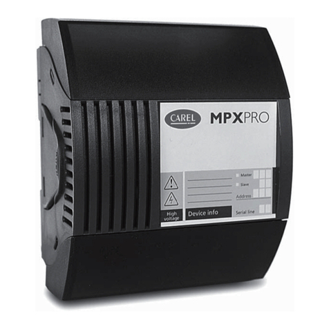
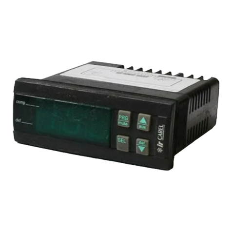
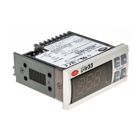
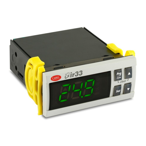
PJS8* is a microprocessor electronic controller with LED display for the
management of refrigerated compressed air dryers. The refrigerated dryers
managed by PJS8* Dryer are equipped with ON/OFF compressors.
Available supply voltages of easy dryer are 230 Vac, 115 Vac or 12 Vac-Vdc
PJS8* is suitable for controlling dryers with independent management of the compressor
(evaporator probe) and the condenser fan (condenser probe) in the 3-relay version PJS8C*.
Condensate drainage is activated by a relay controlled at fixed intervals, depending
on a specific parameter, independently of the activation of the compressor and fan. The
condensate drain function operates continuously when the unit is ON.
On PJS8Y* models equipped with two relays only, the compressor and fan are managed
using the same relay (with a single probe on the evaporator), and the condensate drain
function is managed by its own relay based on the set times (default setting). Alternatively,
the compressor and condenser fan can be managed separately as on the 3-relay model, in
which case the condensate drain function will no longer be managed by PJS8* Dryer.
The condensate drain relay is sized for a valve with a power consumption of 18 W and cosφ
> 0.7
Operation
PJS8* manages compressor operation based on the value read by the evaporation
temperature probe (probe 1, dew point). The controller manages different operating modes
and temperature ranges. At pre-set intervals (parameter dr2), the condensate is drained,
activated by relay 1 on the models where this is available.
Initialization: At power ON or when switching from OFF -> ON using the button or via digital
input, the compressor remains off for the time set by parameter “c0”, the controller then
switches to Normal operation.
Normal operation:This mode is active when the value read by probe 1 (dew point) is greater
than the threshold set for StL. The compressor operates as normal in this mode.
ECO: This mode is active when the temperature read by probe 1 falls below the threshold
set for StL and remains below the threshold for a minimum time, set for tE. The compressor
is off. ECO mode ends when the temperature rises above the threshold set for StH, causing
the compressor to start.
OFF: The controller is still powered on, however all of the functions of the algorithm are
disabled, including the condensate drain function.
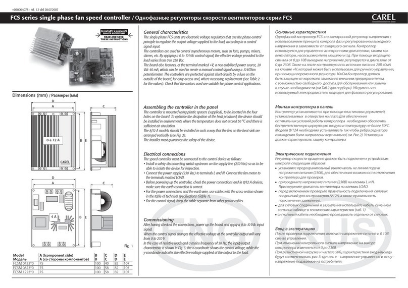
Fan: The condenser fan is activated based on the settings of F4 and F5.When the compressor
is started the first time, the fan will start at F4 + 0.2 degrees to compensate for rapid increases
in temperature. Subsequently, the fan switches on and off at F4 + F5 and F4. By setting F6 =
1, probe 2, the fan and the related alarms are disabled.
Condensate drain: The drain relay is activated at pre-set time intervals. This controls a
valve to drain the condensate. The activation interval and the opening time depend on the
settings of dr1 and dr2. The valve can be activated manually by pressing the DOWN/DRAIN
button.
Alarms
ALARM TYPE CONDITIONS EFFECTS
High dew point Compressor running see alarms
and signals
table
probe 1 value greater than“Adp” for the time “tdp”
Probe 1 dew point probe 1 value exceeds the faulty probe limits
(-50.0/+90.0°C)
High temperature compressor stopped
probe 1 value greater than“dh1”for the time “dtH”
Low temperature with
compressor OFF
compressor stopped
probe 1 value less than“L1” for the time “tL”
Note: this alarm is only monitored after switching from OFF -> ON using the
button, during the compressor OFF time“c0”.
Low temperature with
compressor ON
compressor running
probe 1 value less than“L2” for the time “tL”
Condenser probe 2 probe 2 value exceeds the faulty probe limits
(-50.0/+90.0°C)
Alarms and signals table
Alarm message compressor fan valve buzzer reset
ECO mode ECO OFF Depends on
probe 2 Timed OFF automatic
High dew point Adp OFF Depends on
probe 2 Timed ON manual
Condensate drain drn Independent Depends on
probe 2 Timed OFF automatic
Dew point probe
alarm P1 ON Depends on
probe 2 Timed ON automatic
Condenser probe
alarm P2 ON Depends on
probe 2 Timed ON automatic
High temperature
alarm H1 ON Depends on
probe 2 Timed ON automatic
Low temperature
with compressor OFF L1 OFF Depends on
probe 2 Timed ON automatic
Low temperature
with compressor ON L2 OFF Depends on
probe 2 Timed ON manual
External alarm AI OFF OFF closed ON Automatic
OFF status OFF OFF OFF closed OFF Automatic
Unit parameter error EE OFF OFF OFF OFF Call techni-
cal service
Operating parameter
error EF OFF OFF OFF OFF
Manual
with factory
reset
Probe 1 temperature reading
There are three temperature ranges displayed, defined by the pair of parameters“r5”and
“r6”:
• Temperature between r5 and r6: the display shows the message“On”. Pressing Up+Set
for 2 seconds, the temperature is displayed for 30 seconds.
• Temperature lower than r5 or higher than r6: the display shows the actual value read by
the probe, filtered with a suitable coefficient to avoid sudden changes or instability of
the displayed value.
Logging
The controller can log some variables of interest to the user and make them available on
the user interface.
Par. Description UOM Min. Max. Default Visibility Note
ECd Percentage of ECO mode in
the last /3 hours % 0 100 0 C Read-only
ECY Percentage of ECO mode
since last reset % 0 100 0 C Read-only
ECh No. of hours in ECO mode
since last reset hours 0 32000 * 0 C Read-only
Ch No. of hours with compressor
ON since last reset hours 0 32000 * 0 C Read-only
Mh Total unit hours hours 0 32000 * 0 C Read-only
ndP Number of high dew point
alarms - 0 999 0 C Read-only
nH1 Number of high temperature
alarms - 0 999 0 C Read-only
nL1 Number of low temperature
with compressor OFF alarms - 0 999 0 C Read-only
nL2 Number of low temperature
with compressor ON alarms - 0 999 0 C Read-only
* When the hours exceed 999, the display shows a decimal point, indicating that the value
is to be multiplied by x1000.
Example: 3.3 = 3300 hours; 12.8 = 12800 hours
Electrical connections
Fig. 4
1 2
3
4 5 6
7
9 10 118
L
L N
8(4)A 10(10)A EN60730-1
8A 2FLA 12LRA 12A 10FLA 60LRA UL 873
COND. T.
DI / NTC
D.P.T.
NTC
PROBES
or
SERIAL
CONV
PROG.
KEY
-10T50
250 Vac
230 Vac/
or 115 Vac/
or 12 Vac/Vdc
PJS8C0H**
1 2 3 4 5 6 7
9 10 118
L
L N
8(4)A 10(10)A EN60730-1
8A 2FLA 12LRA 12A 10FLA 60LRA UL 873
DEF. T.
DI / NTC
AMB. T.
NTC
PROBES
or
SERIAL
CONV
PROG.
KEY
-10T50
250 Vac
230 Vac/
or 115 Vac/
PJS8Y0H**
NO POWER
& SIGNAL
CABLES
TOGETHER
READ CAREFULLY IN THE TEXT!
Technical specications
power supply (*) 230 Vac +10 /-15% 50/60 Hz; 115 Vac +10 /-15% 50/60 Hz
12 Vac +10/-15% 50/60 Hz class 2; 12 Vdc +10/-20% class 2
nominal power 3.5 VA
inputs (*) NTC probe 1 or 3 inputs.
Digital input as an alternative to a third probe
relay outputs (*) 2 Hp relay UL: 12 A Res. 10 FLA 60 LRA - 240 Vac
EN60730-1: 10(10) A 250 Vac (**)
8 A relay UL: 8 A Res. 2 FLA 12 LRA - 240 Vac C300,
EN60730-1: 8(4) A NO, 6(4) A NC, 2(2) A CO - 250 Vac
probe type (*) NTC Std CAREL 10 KΩa 25 °C
connections (*) Plug-in terminals for screw blocks or with crimped contact (cable cross-
sect. up to 2.5 mm²). Rated maximum current per terminal 12 A.
assembly (*) using screws from the front panel or with rear brackets
Display 3 digit LED display with sign (-199 to 999) and decimal point; six status
LEDs
operating conditions -10T50 °C - humidity <90% RH non-condensing
storage conditions -20T70 °C - humidity <90% RH non-condensing
range of measurement -50T90 °C (-58T194 °F) - resolution 0.1 °C/°F
front ingress protection panel mounting with gasket: IP65 type 1
Case plastic terminal, 81x36x65 mm
class of protection against electric shock Class II when correctly incorporated
environmental pollution Normal
PTI of insulating material 250 V
period of stress across the insulating
parts Long
heat and fire resistance category category D (UL94 - V0)
surge protection immunity category 1
type of action and disconnection relay contacts 1C
no. of relay automatic switching ope-
rations (*) EN60730-1: 100.000 operations
UL: 30.000 operations (250 Vac)
software class and structure Class A
cleaning use only neutral detergents and water.
maximum cable length serial: 1 km; probes: 30 m; relays: 10 m
WARNING:
do not run power cables less than 3 cm from the bottom of the device or from the probes;
use only copper cables for the connections.
(*) The characteristics indicated differ according to the model.
(**) Minimum T OFF between two motor starts must be greater than 60 s..
IMPORTANT WARNING
The CAREL product is a state-of-the-art product, whose operation is specified in the technical documenta-
tion supplied with the product or can be downloaded, even prior to purchase, from the website www.carel.
com. The customer (manufacturer, developer or installer of the final equipment) accepts all liability and risk
relating to the configuration of the product in order to reach the expected results in relation to the specific
final installation and/or equipment. Failure to complete such operations, which are required/indicated in the
user manual, may cause the final product to malfunction; CAREL accepts no liability in such cases. The custo-
mer must only use the product in the manner described in the documentation relating to the product. The
liability of CAREL in relation to its products is specified in the CAREL general contract conditions, available on
the website www.CAREL.com and/or by specific agreements with customers.
Parameter Table
Simb. Parametro Carel
Type
Carel
Address
Modbus
Type
ModBus® Visibility Min. Max. Def. UoM
PS Password I 20 reg 148 F 0 200 22
/2 Measurement stability I 21 reg 149 C 1 15 4
/3 Number of hours to monitor Ecd I 22 reg 150 C 1 24 8
/4 Selection of the displayed probe I 23 reg 151 C 1 3 1
/5 Selection °C / °F (0 = °C; 1 = °F) D 31 coil 31 C 0 1 0
/6 Disable decimal point D 32 coil 32 C 0 1 0
/C1 Calibration probe 1 A 9 reg 9 C -12,7 -12,7 0,0 °C/°F
/C2 Calibration probe 2 A 10 reg 10 C -12,7 -12,7 0,0 °C/°F
StL Low dew point setpoint A 12 reg 12 C -2 100 0,0 °C/°F
StH Upper dew point setpoint A 13 reg 13 C 0,0 100,0 12,0 °C/°F
L1 Low temperature alarm threshold with
compressor OFF A 14 reg 14 C -50,0 200,0 2,0 °C/°F
L2 Low temperature alarm threshold with
compressor ON A 15 reg 15 C -50,0 200,0 -2,0 °C/°F
r5 Lower display limit A 16 reg 16 C -2,0 r6 3,0 °C/°F
r6 Upper display limit A 17 reg 17 C r5 200,0 7,0 °C/°F
tE ECO mode activation time I 25 reg 153 C 1 199 60 min
tE1 Minimum time of ECO mode I 26 reg 154 C 1 199 5 min
tL Low temperature alarms activation
time I 29 reg 157 C 0 90 2 sec
c0 Start delay of compressor and fan
at power on I 32 reg 160 C 0 200 1 min
c1 Minimum time between consecutive
compressor starts I 33 reg 161 C 0 100 3 min
c2 Compressor minimum off time I 34 reg 162 C 0 100 1 min
c3 Compressor minimum on time I 35 reg 163 C 0 100 0 min
c4 Compressor safety (duty setting) I 36 reg 164 C 0 100 0 min
dr1 Condensate drain time I 38 reg 166 F 1 20 1 sec
dr2 Drain time interval I 39 reg 167 F 3 60 6 min
d/ Probe 2 reading A 1 reg 1 C 0 0 0 °C/°F
dC Time base (reserved) D 37 coil 37 C 0 1 0
Adp High dew point alarm threshold A 24 reg 24 C 1 100,0 17,0 °C/°F
tdp Adp activation delay I 47 reg 175 C 0 60 6 min
h1 High temperature alarm threshold
with compressor ON A 25 reg 25 C -50,0 200,0 50,0 °C/°F
tH h1 activation time I 48 reg 176 C 0 90 30 sec
A4 Digital input configuration I 49 reg 177 C 0 2 0
F0 Fan ON delay I 61 reg 189 C 1 100 3 sec
F4* Fan off temperature A 28 reg 28 C -50 200 40 °C/°F
F5* Fan on differential A 29 reg 29 C 0,1 100 1 °C/°F
F6* Disable fan probe I 62 reg 190 C 0 1 0
H0 Serial address I 65 reg 193 C 0 207 1
H2 Enable keypad I 66 reg 194 C 0 3 1
H4 Disable buzzer D 39 coil 39 C 0 1 0
H5 Key ID code from supervisor I 67 reg 195 C 1 199 199
EZY Select Easy set bank I 68 reg 196 C 0 4 0
(*) parameters not present on models with 2 relays.
Note: the “Easy Set” parameter can be used to select one of the 4 quick configuration sets
stored on the device, each containing a maximum of 25 parameters.
Table of functions activated by button
Button Normal operation Start up
Pressed alone Pressed in combination Pressed
alone
Pressed in
combination
Up-On Off more than 3 s: switch
ON/OFF
Pressed
together,
activate
the
manual
alarm
RESET pro-
cedure
- -
Down-
Drain
more than 3 s:
activate/deactivate
condensate drain
Pressed
together,
display the
logged
variables
for 1 s
display
firmware
version
Pressed
together,
activate
the default
parameter
RESET
procedure
Set - more than 3 s:
access the parameter
setting menu (enter
password‘22’)
- Mute audible alarm
(buzzer)
- Reset logged
variables
for 1 s
RESET
current
EZY set
Access and set type F (frequent) and type C (configuration) parameters)
1. press SET for 3 s (the display will show“PS”);
2. • to access the type F and C parameter menu, enter the password “22”using UP/DOWN;
• to access the F parameter menu only, press SET (without entering the password);
3. scroll the parameter menu using UP/DOWN;
4. to view/set the values of the displayed parameter, press SET, then UP/DOWN and finally
SET again to confirm the changes (thus returning to the parameter menu)
To confirm and save all of the new values and exit the parameter menu, press and hold SET
for 3 s;
To exit the menu without saving the new values (exit by timeout), do not press any button
for at least 60 s.
Supervisor protocol on RS485 network
Automatic recognition of the network protocol: Carel or Modbus®
Accessories
• CAREL IROPZKEY* programming key (for duplicating the parameters)
• CAREL IROPZ48500 RS485 converter (for the RS485 supervisor network)
• CAREL CVSTDUMOR0 USB/RS485 converter for interfacing an RS485 network to a perso-
nal computer via the USB port
• VPM, program downloadable from http://ksa.carel.com. This tool can be used to set-up
the controller from a computer, program the parameters and update the firmware
Safety instructions
complies with the relevant European standards.
Installation precautions:
• the connection cables must guarantee insulation up to 90 °C;
• for 12 Vac versions use class II transformers. To comply with EN 61000-4-4, EN 61000-4-5,
EN 61000-4-11, EN 61000-4-6, EN 60730-1, the transformer must be one of the models
indicated (see the CAREL price list). For the 12 Vac/dc versions, as it is not possible to
guarantee double insulation between the power connectors and the relay outputs, it
is recommended to only use safety extra low voltage loads (nominal effective value up
to 42 V);
• allow a space of at least 10 mm between the case and nearby conductive parts;
• digital and analogue input connections less than 30 m; adopt the appropriate cable
separation measures to comply with the aforementioned regulations.
• Secure the output connection cables so as to avoid contact with safety extra low volta-
ge parts.
NO POWER
& SIGNAL
CABLES
TOGETHER
READ CAREFULLY IN THE TEXT!
WARNING: separate as much as possible the probe and digital
input signal cables from the cables carrying inductive loads and
power cables to avoid possible electromagnetic disturbance.
Never run power cables (including the electrical panel wiring)
and signal cables in the same conduits.
Disposal of the product
The appliance (or the product) must be disposed of separately
in accordance with the local waste disposal legislation in force.
