manuals.online logo
Brands
  1. Home
  2. •
  3. Brands
  4. •
  5. Carrier
  6. •
  7. Air Conditioner
  8. •
  9. Carrier 38HDF018-036 Dimensions and installation guide

Carrier 38HDF018-036 Dimensions and installation guide

Other manuals for 38HDF018-036

1

This manual suits for next models

1

Other Carrier Air Conditioner manuals

Carrier 40MAQ User manual

Carrier

Carrier 40MAQ User manual

Carrier 38TOVG010-703 User manual

Carrier

Carrier 38TOVG010-703 User manual

Carrier GAS FURNACE 58MXA Operating instructions

Carrier

Carrier GAS FURNACE 58MXA Operating instructions

Carrier 40SMC N Series Technical Document

Carrier

Carrier 40SMC N Series Technical Document

Carrier MODULINE 37HS User manual

Carrier

Carrier MODULINE 37HS User manual

Carrier 50HC Series Installation and user guide

Carrier

Carrier 50HC Series Installation and user guide

Carrier 48MPD Dimensions and installation guide

Carrier

Carrier 48MPD Dimensions and installation guide

Carrier 38EN Instructions and recipes

Carrier

Carrier 38EN Instructions and recipes

Carrier WeatherExpert 48N2 User manual

Carrier

Carrier WeatherExpert 48N2 User manual

Carrier LUVH025N User manual

Carrier

Carrier LUVH025N User manual

Carrier CA13NA 018-060 Quick start guide

Carrier

Carrier CA13NA 018-060 Quick start guide

Carrier PREMIER 52P SERIES Quick start guide

Carrier

Carrier PREMIER 52P SERIES Quick start guide

Carrier WMVC Series User manual

Carrier

Carrier WMVC Series User manual

Carrier 40MBQB09D--3 User manual

Carrier

Carrier 40MBQB09D--3 User manual

Carrier 38TDB Instructions and recipes

Carrier

Carrier 38TDB Instructions and recipes

Carrier LUVH080K User manual

Carrier

Carrier LUVH080K User manual

Carrier P5 Series Service manual

Carrier

Carrier P5 Series Service manual

Carrier Comfort 48VLUK Series User manual

Carrier

Carrier Comfort 48VLUK Series User manual

Carrier 50PG08 14 Series User manual

Carrier

Carrier 50PG08 14 Series User manual

Carrier 48GP (N) 024-060 User manual

Carrier

Carrier 48GP (N) 024-060 User manual

Carrier 40WAW007-024 User manual

Carrier

Carrier 40WAW007-024 User manual

Carrier Holiday 51AKB User manual

Carrier

Carrier Holiday 51AKB User manual

Carrier 48ES-A36 Instruction Manual

Carrier

Carrier 48ES-A36 Instruction Manual

Carrier 40GJB User manual

Carrier

Carrier 40GJB User manual

Popular Air Conditioner manuals by other brands

Fujitsu ASYG 09 LLCA installation manual

Fujitsu

Fujitsu ASYG 09 LLCA installation manual

York HVHC 07-12DS Installation & owner's manual

York

York HVHC 07-12DS Installation & owner's manual

intensity IDUFCI60KC-3 installation manual

intensity

intensity IDUFCI60KC-3 installation manual

Frigidaire FAC064K7A2 Factory parts catalog

Frigidaire

Frigidaire FAC064K7A2 Factory parts catalog

Sanyo KS2432 instruction manual

Sanyo

Sanyo KS2432 instruction manual

LG MultiV Series installation manual

LG

LG MultiV Series installation manual

CLIMAVENETA a-CHD U-2T 606+2209 OPERATING AND INSTALLATION Manual

CLIMAVENETA

CLIMAVENETA a-CHD U-2T 606+2209 OPERATING AND INSTALLATION Manual

Midea EWK06CW5 user manual

Midea

Midea EWK06CW5 user manual

Pioneer FAB Series installation manual

Pioneer

Pioneer FAB Series installation manual

SPT WA-1511S user manual

SPT

SPT WA-1511S user manual

Mitsubishi Electric Mr.Slim MSZ-A24NA operating instructions

Mitsubishi Electric

Mitsubishi Electric Mr.Slim MSZ-A24NA operating instructions

Mitsubishi Electric PUHZ-RP50VHA4 Service manual

Mitsubishi Electric

Mitsubishi Electric PUHZ-RP50VHA4 Service manual

Panasonic CS-S18HKQ Service manual

Panasonic

Panasonic CS-S18HKQ Service manual

Panasonic CS-E15NKE3 operating instructions

Panasonic

Panasonic CS-E15NKE3 operating instructions

Gree GWH18TC-K3DNA1B/I Service manual

Gree

Gree GWH18TC-K3DNA1B/I Service manual

Friedrich ZoneAire Compact P08SA owner's manual

Friedrich

Friedrich ZoneAire Compact P08SA owner's manual

Daikin R32 Split Series installation manual

Daikin

Daikin R32 Split Series installation manual

Daikin FFQ09Q2VJU Operation manual

Daikin

Daikin FFQ09Q2VJU Operation manual

manuals.online logo
manuals.online logoBrands
  • About & Mission
  • Contact us
  • Privacy Policy
  • Terms and Conditions

Copyright 2025 Manuals.Online. All Rights Reserved.

38HDF018-036
Duct Free Condensing Units
38HDR018-060
Ducted Condensing Units
Installation, Start-Up and
Service Instructions
CONTENTS
Pa_
SAFETY CONSIDERATIONS ...................... 1
INSTALLATION ................................ I l0
Step 1 -- Complete Pre-lnstallation Checks ...... I
• IfNPACK UNIT
• INSPECT SHIPMLNT
•CONSII)I R SYSTLM REQUIREMI NTS
• MVI'CHINGTHI CONI)INSINGUNIT'I_)AN
INDOOR UNIT
Step 2 -- Rig and Mount Unit ..................... 3
• Me! ;NTINC, ON GROUNI)
•MOIINTINGONROOF
• RIGGING
Step 3-- Complete Refrigerant Piping
Connections ................................... 3
• CHI('KACC!JR,VI'IH<CONTI<GI,
•FII:I'ERH<IEI _.
• MAKEPIPINGS\\EXI'('ONNIMTOI_S
• PROVII)I SAFETY P.LI,Ilff _
Step 4 -- Make Electrical Connections ........... 6
• L'ONTROL ( *II_( [fiT WII<ING
•POWI:I_ WIRING
• CONNECTIONS T() I)UCTFPd I FAN COII, UNITS
START-UP ....................................... 1l
SERVICE ..................................... II 14
MAINTENANCE ................................. 14
TROUBLESHOOTING .......................... 14.15
INSTALLATION
Step 1-- Complete Pre-lnstallation Checks
ITNPACK !INIT (Sue Fig Ii Move the' unit Io lina] 1o_1
[ioll R<'move ufli[ horn _:lr[t_ll, buillg calefil[ rlol 10 d_llllag_'
selvice valves and gdik's
SAFETY CONSIDERATIONS
Ins{!lling and servicing air conditioning equipmenl can I_
]l_lz_lfdotls dtl_ {t) Sys[el31 pl_2ss[Ife _Ii_d _[ec[lica[ _)131polluil[s
Only tmhl_l and qualified service i_rsonnel shoukl insla[] or
service air conditionhlg equipmenl
Ull[r;til_ed i_rsofll_el c_n _rforl_l basic mail_l_llaflce, such
as cleaning and replacing lillers All olher operations should be
perk)filial by train_i service persollll_2] Wll_ll WOJkill_2oil air
condilioning equipment, observe sa_ly p_cautions hi ]ilera
tuJ_, lags. and ]abels atlached Io unil
Fol]<>_ a[] sa_{y codes¸ Wear sa_ly glasses and work
gloves U_ quenching clolh lbr _azing operations¸ Have life
exthlguisher available¸ Re_l Ihese ins_ruc{ions _oroughly_
Consuil k_al building codes and tile Naliona] Elec{rica] Code
/NI_:) I_>l¸s_._cial insta[]alion requh_menls
Beh_rc inslalling o_ servicing syslem, always mm off main
power [o sysl_ll_ There may be i_loJ_ [hall olle digcollll_c[
_wilch Turn offaccessory healer power if applicable L]ec
hica] shock carl catlse seli<)lls _1 solla[ illith y
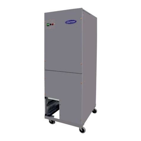
Fig. 1 --38HDF,HDR Unit
INSPECT SHIPMLNT File a claim wilh the shipping
company if shipmcnl is d_lmag_d or incomplete Check uni_
flamep]a[_2 [o ellsufe_ulli[ ii_a[ches job fe_quirelll_2IllS
CONSIDER SYSTEM REQUIREMENTS Consult local
building c<×les and NEC fi_rspecial hlsla][alion requiJ_ments
Allow su_icienl space l_>rairflow clearance, wiring, _ffig
eran_ piping, and servicing unit¸ See Fig 2
I,oc_ll_ tlfli[ so [ha[ colld_211serairflow is tll_l_2sIricRxi<>l__)[h
sides¸ Rear to I_g 2
Unil may be moun{ed on a level pad directly on base legs or
mounled on raised pads al sup_>l_ points See Fig 2 I_>l¸cenler
of gmvily
M_VI'CHING THE CONI)ENSING UNIT TO AN
INDOOR UNIT The 38HI)EHDR unit_ can be match_l _o
a _rresponding ind<×)r uni_ The 38HDI_I18 036 units can be
ma{ched with an in cei]hlg casse_ or high wail indoor unJl
llle 38HI)R unil can be malched with underceiiing and resi
dcntia] l_n coils¸ Re_l ¸ to separate hl(k×)r uni_ ]itemltne Ibr
Manufacturer reserves the right to discontinue, or change at any time, specifications or designs without notice and without incurring obligations.
Book _ 4C_talog NO 02-38HDOOO1 S[ Printed in US A Form 38HD_,SI Pg _ 1-o6 Replace_: 38NDC 3SI
UNIT MODELS CHAG_IG
38HDF 38HDR _IZE A B C D
Unil _ze Unit _ze {Refere_el
t_18 t_18 0 2_11½_ 3_01_/1_ _ 1_2_/1__ 1_ _
/638_21 /938_21 /369_9) /40&4)
924,930 924 O,6 2'71/6 _' 3,_1_/16 _, 1,2_/16 _, 1,4 _
/790_6) /9382) /369_9) /406_4/
3, 1_/1__, 3, 8_1_, 1, 5_1__, y_7/1_"
_6 _6 _0 /944_6) /1131,9) /433_4) /46&3)
_)48_t_6_ 1 6 3_ 7_/_ _ 3_ 8_/_ _ 1_5V_ _ 1_ 6_/_e_
/10971 /1131_9) /433_4) /488_3)
NOT_: D_rre_s_ons s_ow_ In feet _ncbes, D_rne_s_ons Jn/ ) a_e _r_Hrrete_s_
E F G H J K L N P
1117/1_ ¸_ 15_/1_ ¸ 151½ ¸_ 110 ¸_ 11_ 065/_ 0111/_ ¸_ 021_/1_ ¸¸ 06 _
/895_3) /436_6) /43_) /5_9J) /33D_21 /168_3) /288_B) /78) / 182_41
1_17/1_ 1_/1_ 1,_11/_ ¸_ 2_.4_ 1_2_ 0_/_ 0_11_/_" 0_21_/1_" 0_ _
/595_3) /436_6) /887_4) /711_5) /35_6) /171_8) /295_3) 175_ /182_4)
2,_1/2 ¸, 17_/_ ¸, 2,5_/1_ ¸, 2,101/1_ ¸, 1111/1_ ¸, r}81/_ , 137/_ , r}37/1_, r_l/2,
/774_71 /498_5_ /7411 /865_5) /347,71 /206_4) /403_2) /88) /165_4)
2_6_½_ 1_7_ _ 2_ 1_/_ _ 3_V_e _ 1_2_½_ 0_8V2 _ 1_ 6_/__ 0_/_ _ (_ 6_/2_
(774_7) /498_5) /893_4) /1017_g) /35421 /215_9) /479 41 /88) 065_4)
_[_D BAFFLE _CCESSO_
1
-A-
FRO\T Eii
@
M OPERATING WT
UNIT _IZE i_ mm Ib k_
018 % 18¸88 166 753
_)24 _ 18_88 176 79_8
38HDF _/4 19_05 187 84_8
t_18 % 18_88 166 75_8
t_24 % 18_88 176 79_8
38HDR _6 _/4 19_05 250 113_4
948 _ 22_22 278 126_1
_L 4 -
(4O6)
MINIMUM MOUN_NG PAD
DIMEN_ION_
UNIT ,£1ZE S_pport Feet
CHA_I_ _IZE_ t_& _6 1_ 11_ x 3 _6 _ 884_2 x 1066_8
CH A_I_ _IZE_ 1 & 1_6 2_4_" × ,_ 2 _ 609_6 x 1270
NOTES;
1 Required _ea_anoes: W_h ¢o_ faring walt a_ow 6 in m_nim_ m clearance
on coil _q,le and cr,_ end, and 3 feet minimum o_earance on or,r_p_essor
en_ and fan s_e, W]t_ fan fa_g ,_,_L al_o_ 8 _n__r_nlrnu_r c_e_anoe on
fan s_e and o_ end_ _nd 3 feet r _in_mur_ _1ea_noe on oomp_esso_ end
and _o_1_de_ With mu_ 4_t a_#_atio_ arrange u_s so diSOha rge of o_e
does not en_e_inlet ,,f anothe_
2_ _ m erkslo_s In _ a rer_es_ a_e _nrlHimete_
3_ Cente/oI G/aV_y
, FIELD _,OWEI__Ur,pL_¸ CONN
7/8"(22_) W2"TRA0_
(FI_D pROVIDED AND INST_LE D_
Fig. 2--38HDF, HDR Unit Dimensions
Step 2 -- Rig and Mount Unit
MOUNTING ON GI_.OUND M_unl und on a solkL level
(OTI_Wk" ptd Posilioll ufld so \_ll_l oI i(e I_oln 1(iol do_s ilo_
ldl dire_ll_ ohio unil Access_r_ shaking kils cm be used
_hell Llnds fie hi _X_ skKke(J _ee il]slai[ali(lll illshtl_[ioI1s
pm_Med _ilh Ihe a cessoJ_ kd Use fieM pm_ided sno_ sltnd
ol KU IKk _ [l_re plo[ongud subhuezillg le ml_'l ilules ol [1_*I\ _
Silo _\ O_( UIS
It ollddiolls or k_.aJ codes reqtlh e Lllli( bu hs R'l_ed k) a ptd,
6fiekl supplied liedo_\n I×)ll_ shouM I'_= used and Hsl_'nrd
Hlrough slol_ pro\ kk'd in uni_ mounli ng kx'l
MOUNTING ON ROOI Mounl uni[ /)n a level plall_)Hn
OI lllm_ _ tl lels[ 6 ill abo_e Iool suH I_e IsolaR* tIl_i[ ;uld lub
hlg horn ShU lure
RIGGING
Keep Ihe unit updghl and lift unil using a sling Use card
board or p_lding tinder file sling, and sp_ader bars k) pl_venl
sling damage to the unit¸ See Fig 3 See Fig 2 _r cenler of
_avity re_nce Install the unit so thai Ihe _il does nol _ce
ink>pJ_vailing winds¸ Il¸Ibis is nol _>s_ible and constant wields
a_>ve 25 mph are ex_cl_l, use accessory wield baffle¸ See
inslallalion instructions p_)vid_d with the accessory ki_
NOTE: Accesso_ wind baffles should be us_l on all units
with access(_y low ambiel_t I_ll_pera[ul_2 coil ffol
Field _lbrica[ed sllow or ice slailds may be used to raise [lld[
when operation will be _quired during winler monlhs Units
ii_w also Ix'_wall motll_i_xl tlShlg Ihe acc_ssoly wall IllOUll[hlg
ki_
When mo_e Ihan 50 1}of flltercomlecthlg [ubing alld molv
Ihan 30 fi (If verlical lift is used. consult Ihe residenli fl long line
applicalhm inslmctkm gukie. Fo_ long Ihle _pplications. inler
connecting lines ove_ l(X) I_must be installed wilh a liquid line
solenoid A liquid line olenoid may a13o _v installed on some
unils to improve parl I(×ld eHlciency Reier to Ihe ARI (Air
Conditioning & Rehigeralion Insldule) Directory
II eilhe_ _cl_ig_ranl tubing o_ indoo_ coil is exposed Io
Ihe almosphem, the syslem mtlsl be evactHled lollowing go(_i
_efligcralion p_acfices
Run rehigemnl tulx's as direclly as possible, avoiding
unnecessary lu_ns and bends. Suspend _ehigcmnl lubes so they
do IIOI (hlmage illsula{ioll OI1 vapor [tll%" alld do IIOI[r_lllSl_li[
vibralion to strucltm" Also, when passing reMgerant tnlx:s
thmu_ a wall. seal Ihe opening so Ihal vibratkm is nol ImnsmiF
led to sffuctmv Ix'ave some slack in _vhi_erant tubes belween
sff[ic[lll_, alld ollld<×/i tlfli{ Io absorb vibratioll I_eler to separale
ind_ und inslallation instm_ {ions h_ additional inlbnnation
CHECK ACCURATERCONTROI, The correct Accu
Raler (byl_ass lylx') rehigeranl conhol is required h_r syslem
capaclly oplimization An AccuRaler device wilh field
_eplaceable pislon (see Elg 4) ix supplied wdh tile ouMoo_ und
Reler k/ tile AccuRaler metering device table in sepmale
indoor unil inslallation illsllucliOllS It) delermine fl_e cormcl
AccuRaler pislon SiZe requhvd Ibr [l_e condenser/evaix)rator
syslem being installed
Pisk)n slyle as shown in Elg 4 ix shipped wilh Ihe unfl Do
no[ ill[el_ha_lge coll_lN)llell[s beIwee_l the AcctlRaler device
types Matching of ould<x_ unil with indoor und may requhv
hekl rephcemenl of pislon I).epl _ce pislun, if required, _vl/>_v
_x/nnecfing _eldgemnl lines See Hg 4 Pislon _vplacemenl
illSIltlC[kH1S are hlcluded ill the indoo_ lind iilsl{dia[ioll ills{lilt
lions A[ler syslem inslallation is complele, see Ihe Rehigeranl
Chaffing section on page 12 to dleck and/or adlust _vffigelanl
cha_ [x"
FIUFER I)RIER The ldle_ drier mtlsI be _eplaced whenev
er Ihe _<'higeralion system is exposed to Ihe atmosphere See
Fig 4 lot filler drier inslallalion
;OMPRESSOR
CAP W_Ttl ORiFIGE gODy
NOTE: Arrow on AccuR_ter body points in free flow direction _w_y from tho
indoor coil¸
Fig. 3 -- Lifting Unit with Sling
Step 3 -- Complete Refrigerant Piping Con-
nections- Ou_d<×_unils ma_ b_, .)nnecled Io indoor
unds using fieki supplk'd [ubing ol _efiigeranl g_lde and ondi
Ik>n Sr_' "hbles IA and 1B tbr conec{ line sizes I)o nol use
less Ihan 10 I_ol ink'_ onneding lubing
(By OTHERS}
COBLINB
38HDFO18-036
_BYO_HE_
I)O NOT I3IIRY MORE THAN 36 IN OI REFRI( ER
AN[[" PIPE IN THE GROUND Il¸ any see{ion of pipe i_
buried. _l_ere mus_ be a 6 in vertical rise _(>the valve
collnec[iol_s o1_ the oukl(x)l ¸ uidL II ¸ 13lore thall [he
recommend_l lengfl_ ix buded reffi_ant may migrate to
cooler, bud_l section durhlg exlend_l _d(_s of syslem
shuMown This causes refii_ranl slugghlg and could
possibly dama_ Ihe comp_ssor al starl up
_B¥ aTHEgm
38HDR018-060
Fig. 4 -- AccuRater (Bypass Type) Metering
Device Components
Only use _lcloJ} specil]ed liquid lille I]ltt'r (biers with ratt'd
working pl_ssures less than _X) psig
N( TI'E: Do nol install a suction line fillel ¸drier in liquid line¸
MAKE PIPING SWI! _[" C( )NNKCTIONS Remow plastic
caps from liquid and suction service wllves Use _igel_lfll
_ade lubintz Service valves are closed fl_m the _lctory and aE_
le_ly _r br_lzing Aller wrapping _he service valve wilh a we[
clolh, the tubing _l call be brazed to the sel vice valve usin_ ei
Iher silver beariEl_aor non silver bearing brazing mal_dal C_/l_
suit local c_le _quJr_menls I{_fligemflt _ubing arid the indoor
coil a_ now J_ly _ leak les_ing
N(_'E: Unil is shipp_I with R 4i0A _lclory charge indical_I
P_lss nitmtzcn _ olher inerl gas through piping while br_lz
ill_ Io p_velll _ll IllalJ Oil Of copier oxid_
Table 1A --38HDF018-036 Physical Data
UNIT 38HDF 018 024 030 036
NOMINAL CAPACITY (Tons) 1.5 2.0 2.50 3.0
OPERATING WEIGHT (Ib) 166 176 187 250
REFRIGERANT TYPE R=410A
METERING DEVICE AccuRater (Located at Fan Coil)
CHARGE (Ib)* 4.8 5.3 5.0 7.1
OUTDOOR FAN
Rpm/Cfm 840/1720 840/1720 840/1720 850/1720
Diameter (in.) 18 18 18 24
No. Blades 3 3 3 3
Motor (hp) l& l& l& 1/4
OUTDOOR COIL
Face Area (sq ft) 5.82 7.27 7.27 12.1
No. Rows 2 3 3 2
FPI 20 20 20 20
HIGH PRESSURE SWITCH
Cut-In (psig) 420 ± 25 420 ± 25 420 ± 25 420 ± 25
Cutout (psig) 650 ± 10 650 ± 10 650 ± 10 650 ± 10
LOW PRESSURE SWITCH
Cut-In (psig) 45 ± 25 45 ± 25 45 ± 25 45 ± 25
Cutout(psig) 20± 5 20± 5 20± 5 20± 5
REFRIGERANT LINES
Connection Type Sweat
Liquid Line (in,) OD 3/u 3/u 3/u 3/e
Vapor Line (in.) OD % % 3/4 3/4
Max Length (ft) 200 200 200 200
Max Lift (ft) 65 65 65 65
Max Drop (ft) 150 150 150 150
COMPRESSOR
Type Scroll
Model ZP16KSK-PFV ZP21 KSK-PFV ZP25KSE-PFV ZP34K5P-PFV
Oil Charge (POE - oz) 25.0 25.0 25.0 42.0
Accumulator Yes
CONTROLS
Fusible Plug (F) 210
Control Voltage1" 24 vac
System Voltage 208/230 v 208/230 v 208/230 v I208/230460v,Singlev,3 Phaseand3 Phase,
FINISH Gray
LEGEND _Unit shipped with full factory charge. See ARI (Air Conditioning and
FPI -- Fins Per Inch Refrigeration Institute) capacity table for proper charge a_d piston
POE -- Polyol Ester for each fan coiltype.
t24 v al_d a mil_imum of 40 va is provided in the fan coil unit.
Table 1B --38HDR018-060 Physical Data
UNIT 38HDR 018 024 030 036 048 060
NOMINAL CAPACITY (Tons) 1.5 2.0 2.50 3.0 4.0 5.0
OPERATING WEIGHT (Ib) 166 176 250 250 278 306
REFRIGERANT TYPE R-410A
METERING DEVICE AccuRatel (Located at Fan Coil)
CHARGE (Ib)* 6.3 6.5 10.0 8.9 12.0 12.2
OUTDOOR FAN
Rpm/Cfm 840/1720 840/1720 850/3900 850/3900 850/3900 850/3900
Diameter (in.) 18 18 24 18 24 24
No. Blades 3 3 3 3 3 3
Motor (hp) 1/8 1/8 1/4 1/4 1/4 1/4
OUTDOOR COIL
Face Area (sq ft) 5.8 7.3 12.1 12.1 14.1 14.1
No. Rowe 2 3 2 2 3 3
FPI 20 20 20 20 20 20
HIGH PRESSURE SWITCH
Cut-In (psig) 420 ± 25 420 ± 25 420 ± 25 420 ± 25 420 ± 25 420 ± 25
Cutout (psig) 650 ± 10 650 ± 10 650 ± 10 650 ± 10 650 ± 10 650 ± 10
LOW PRESSURE SWITCH
Cut-In (psig) 45 ± 25 45 ± 25 45 ± 25 45 ± 25 45 ± 25 45 ± 25
Cutout(psig) 20± 5 20± 5 20± 5 20± 5 20± 5 20± 5
REFRIGERANT LINES
Connection Type Sweat
Liquid Line (in.) OD 3/8 a/8 a/_ _/_ 3/_ 3&
Vapor Line (in.) OD s/_ s/8 a/4 _/4 7/8 7/8t
Max Length (ft) 200 200 200 200 200 200
Max Lift (ft) 65 65 65 65 65 65
Max Drop (ft) 150 150 150 150 150 150
COMPRESSOR
Type ScloJJ
oo0 i i i i
ZP16KSE=PFV ZP21K5E=PFV ZP25KSE=PFV ZPZ9K5E=PFV ZP42KSE=PFV ZP51KSE=PFV
25.0 25.0 25.0 25.0 42.0 42.0
Oil Charge (POE - oz)
Crankcase Heater (watts) -- -- 40 s 40 40 40
Accumulator
CONTROLS
Fusible Plug (F) 210
Control Voltage** 24 vac
System Voltage 208/230 v 208/230 v 208/230 v 208/230 v, Single and 3 Phase, 460 v, 3 Phase
FINISH Gray
LEGEND
FPI -- Fins Perlneh
POE -- PolyolE_e_
*Unit shipped with full factory cha_ge. See ARI (Air Conditionh_g
and Refrigeration institute) capacity table for p_oper cha_ge and
piston fo_ each fan coil type.
tValve connection size is 7/8 inch. Recommended line size is
11/_ inches.
*'24 v a_d a minimum of 40 va is provided in the fa_ coiJ u_it.
Step 4 -- Make Electrical Connections
lJfli[ _ ibil_o[ mull have' _lfl Unil_ldrftlp[_*_l, ul_brokdll ele_hi
cal g]ound It>minimi!e Ille possibilily ol pelsonal injmy il
an elec(rical lhtdl shouki occm This glound may consisl of
elecIrical wire comlected to tlili[ gJound Iqg in control Coll_
partmenL oJ cofldlli[ appJoved Iur eleclJical grotllld whell
hlslalled in accordance with NEC, and I(_al electrical
codes Failu;v to lollow this warning couki resull in Ihe
hlslaller behlg liable Ik_ltile pel SoElalinJuly ol odlers
B_JDI_ _r_lrl2qil_g service or mailll_[lallce, bg stirs? illd(×)r
unit mare powel swilch is mnlrd OFF and md/×)r blower
has slopl_'d Pailure Io do so may _'sull m elechical shock
or iEliury hum rolalJ ng hm blades
CONTIEOL CIRCUIT WIRIN( COEllml volta_a" is 24 V
(40 va minhnumi See Fig 5 and unit label diagram _>r l_eld
suppbed wiring delails Rou_e conh_)l wire _hrough opening in
tlllil side pallel IO coIIIl_clioI1 ill UllilCOIlllOI IN)X
NO'I]: For wiJe runs up Io 50 ft. use no 18 %VG (American
Wi_ Gage) instdaled wire¸ I_r 50 to 75 I/. use no 16 AWG
instdaled wire¸ I_r over 75 ft. use 14 AWG insulaled wire¸
NOTE: All wiring mus_ condom to NEC and k,cal c<_es
N()TE: Operating unil on improper line volla_ consliltltes
abuse and could affecl Carder warmnly See I_bles 2 and _
Do n_ install unil in a system where volta_ may flucltlal_
al_>ve or below permissible limits¸
_? _[_lbles 2alld 3 _)r recoml_qelld_xi ftlse ';i/us Whell ill_lk
iil_ eleclrical COiln_2CtiOilS, provide cleara_lce al 1lie [lllit I_)r re
I)i_ranl piping connections
N(_'E: The 38HDF units are suppbed wilh a 24 v control
Ii_llls_l_qer The _HI)R tllli_ _se Ihe c<)llll_)l [lallsl_lrmer
suppbed with _he mal_h_l indo_ unil
POWER WIRING [ hlit is _c_>ry wired ff_r voltage shown
oll ii_ll_q_2plale Prt)vide adequate, I_lst_(l disc()llllecl swilch
within sight _om unit. readily accessible, bul out of reach ol:
children¸ Provision _J locking the swilch open (offl is advis
able to prevent power _om being _unled on while unil is being
servic_l Disconnect swilch, fil_s, and field wiring Enusl
C<_lply wilh Ihe NI_ and local c<_le requirements¸ Use c<>pl_:_r
wire ollly I_tw_?_l the discollll_?cl swilch tiled tlllil Use
Illiilil_q [Iill (_0 C wire _r the _eld _ )'¢,er COilil_CliOll
Roule _>wer wires through _he opening in unil side l×lncl
alld collllec_ ill the tlllil colltrol box as ',howII oil the2 t111itI_ll%'_l
diagram and Fig 6 and 7 Unit mus_ be gl_)unded
CI)NNE(_I'IONS TO DUCTFRI_ FAN COIL UNITS
The 38HDR units are designed _ easy match up to 40QA
ducl _ee _ln coils¸ This unit provides 24 v power ff_r the out
door [lllil _om the _l_l coil¸ Collnec[ Ih_ Y aild C I_r_nillal,, ol ¸
Ihe hldoor ullit I_! 1he Y a_d C lelmhlals
38HDF UNITS 38HDR UNITS
CO_4HON{C)
24V_C (R} R_B _
SbPPLY
F_LO _OP_'LIEO
_'_TAT Wlrl_
_00_ UNZT
LOW VOLTAGE C0NNECT10NS
NOTE: For more information see schematic inside uNt.
£[_LO _PPL lEO
INDO_ UNIT
LOW VOLTAGE CONNECTIONS
Fig. 5 -- Typical Control Circuit Connections
Table2-- 38HDF Electrical Data
38HDF
UNIT SIZE
018
024
030
036
V-PH-Hz
208/230-1-60
208/230-1-60
208/230-1-60
208/230-1-60
208/230-3-60
460-3-60
VOLTAGE RANGE* COMPRESSOR OUTDOOR FAN MOTOR MIN CKT
Min Max RLA LRA FLA NEC Hp kW Out AMPS
187 253 10.0 48.0 0.80 0.125 0.09 13.3
187 253 14.3 58.3 0.80 0.125 0.09 18.7
187 253 15.7 73.0 0.80 0.125 0.09 20.4
187 253 20.0 112.0 1.45 0.25 0.19 26.5
187 253 14.7 88.0 1.45 0.25 0.19 19.8
414 506 6.6 44.0 0.80 0.25 0.19 9.1
FUSE/HACR
BKRAMPS
20
3O
35
45
3O
15
LEGEND
FLA -- Full Load Amps
HACR -- Heating, Air Conditioning, Refrigeration
LRA -- Locked Roto_ Amps
NEC -- National Electrical Code
RLA -- Rated Load Amps (Compressor)
*Permissible limits of the voltage _ange at which unit will operate
satisfactorily.
NOTES:
1. Control circuit is 24 v on all units and requires an external powe_
source.
2. All motois and co r[/pr _/ssor s contain intelnal oveiIoad plotection.
3. In compliance with NEC (U.S.A. Standard) _equi_ements for muF
timotor and _mbination load equipment (refer to NEC Articles
430 and 440), the ove_ou_rent p_otective device for the unit shall
be fuse or HACR breaker.
4. Moto_ RLA values are established in accordance with UL (Under-
writers' Laboratories) Standard 465 (U.S.A. Standard).
5. 38HDF, HDR018-030 units are only available in single-phase
voltage.
6. Unbalanced 3-Phase Supply Voltage
Never operate a motor where aphase _mbalance in suppiy vet,-
age is greater than 2% Use the following formuJa to determine
the percentage of voltage imbalance:
= 1O0 x max voltage deviation from average voltage
average voltage
EXAMPLE: Supply voltage is 460-%60.
A B C AB-452v
BC = 464 v
AC =455v
Average Voltage = 452 + 464 + 455
3
1371
Determine maximum deviation from average voltage:
(AB) 457 - 452 = 5 v
(BO) 464 - 457 = 7 v
(AC) 457 - 455 = 2 v
Maximum deviation is 7 v.
getermil_e percentage of voltage imbalance:
7
% Voltage Imbalai_ce _ 100x 457
1.53%
This amount of phase imbalance is satisfactory as it is below the
maximum aiJowabJe of 2%.
I latMe,PyOfRhTAeNsTu:pCly/talcttYCUpll°c_eli_l_leol;_c_eiHIy c/°rmePt_lt_Y/i_/r/n_*di" I
- 457
Table 3- 38HDR Electrical Data
38HDR
UNIT SIZE
018
024
030
036
048
060
VOLTAGE RANGE* COMPRESSOR OUTDOOR FAN MOTOR MIN CKT
V-PH-Hz Min Max RLA LRA FLA NEC Hp kW Out AMPS
208/230=1 =60 187 253 10.0 48.0 0.80 0.125 0.09 13.3
208/230=1 =60 187 253 14.3 58.3 0.80 0.125 0.09 18.7
208/230=1 =60 187 253 15.7 64.0 1.45 0.25 0.19 21.1
208/230=1 =60 187 253 15.7 77.0 1.45 0.25 0.19 21.1
208/230=3-60 187 253 10.4 88.0 1.45 0.25 0.19 14.5
460=3-60 414 506 6.3 38.0 0.80 0.25 0.19 8.7
208/230=1 =60 187 253 24.3 117.0 1.45 0.25 0.19 31.8
208/230=3-60 187 253 15.6 83.1 1.45 0.25 0.19 21.0
460=3-60 414 506 6.9 41.0 0.80 0.25 0.19 9.4
208/230=1 =60 187 253 29.4 134.0 1.45 0.25 0.19 38.2
208/230=3-60 187 253 17.8 110.0 1.45 0.25 0.19 23.7
460=3-60 414 506 8.6 52.0 0.80 0.25 0.19 11.6
FUSE/HACR
BKRAMPS
2O
3O
35
35
2O
15
55
35
15
65
4O
2O
LEGEND
FLA -- FullLoad Amps
HACR -- Heating, Air Conditioning, Refrigeration
LRA -- Looked Roto_ Amps
NEe -- National Electrical Code
RLA -- Rated Load Amps (Complessor)
*Permissible limits of the voltage _ange at which unit will operate
satisfaoto_ily.
NOTES:
1. Control circuit is 24 v on all units and requires an exter hal powe_
8ouloe.
2. All motols and _mpressors contain internal oveiIoad ploteetion.
3. In compliance with NEC (U.S.A. Standard) _equi_ements for muF
timotor and combination load equipment (refer to NEe Articles
430 and 440), the ove_ou_rent p_otective device for the unit shall
be fuse or HACR breaker.
4. Moto_ RLA values are established in accordance with UL (Under-
writers' Laboratories) Stand_d 465 (U.S.A. Standard).
5. 38HDF, HDR018=030 units are only available in single=phase
voltage.
6. Unbalanced 3-Phase Supply Voltage
Never operate a motor where a phase imbatance in supphl vo_t-
o
age is greater than 2 _ Use the following formula to determine
the percentage of voltage imbalance:
= 100 x r_/ax voltage deviation flora average voltage
average voltage
EXAMPLE: Supply voltage is 460=3=60.
A 8 C AB=452V
_ BC =464v
AC = 455 v
Avelage Voltage = 452 ÷ 464 + 455
3
1371
Determine maximum deviation from average voltage:
(AB) 457 - 452 = 5 v
(BC) 464 - 457 = 7 v
(AC) 457 455=2v
Maximum deviation is 7 v.
Determine percentage of voltage imbalance:
7
%Voltagelmbalance= lOOx 457
= 1.53%
This amount of phase imbalance is satEsfactory as it is below the
maximum allowable of 2%
IIMPORTANT:ContactyourlocaleIectricutilJtycompanyimmedi- I
ately ifthe supply voltage phase imbalance ismo_e than 2%.
= 457
T_AN
LEGEND
C -- Contactor, Compressor _ Terminal (Marked)
CAP -- Capacitor
CCHT -- Crankcase Heater Them_ostat 0 Terminal (Unmarked)
OH -- Crankcase Heater
COMP-- Compressor Motor _ TermEnaIBiock
EQUIP-- Equipment
GND -- Ground • SplEce
HPS -- High-Pressure Switch
LPS -- Low-Pressure Switch -- Factory Wiring
OFIVl -- Outdoor-Fan Motor .... FEe_dControIWiring
OL -- Overload I R I FEe_d Power WErEng
TB -- Terminal Board
TRAN -- Transformer ----- OptEonalor Acce&sory WEre
SplEce (FEeld)
CONTROL COMPONENT ARRANGEMENT
I_ I *i_
i
JUNCTION
BOX
_]&u _m0L _]Rm_ N_E.mCL_52
UNIT COMPONENTS
38H DF OPERATION SEQUENCE
CALL FOR COOLING:
1. Control voltage from fJa_lsformer to tilermostat (24 v).
2. At thermostat 24 v is switched to "G" and "Y."
3. 24 v from thermostat "G" energEzes fan relay at indoor fan coil unit and indoor-fan motor runs.
4. 24 v f_om themlostat "Y" eller gizes tile contactor coil alld tile compressor and outdoor-fall motor will both
run.
6. If the inter hal protection of the corr#ressor or LPS or HPS open, the 24 v to contactor coil will be inter-
rupted. Tile compressor and outdoor-fan motor will stop.
NOTES:
1. Compressor and fan motors are thermally protected.
2. Wire in ace old alice with National Electlical Code (NEC) alld local codes. Replace
any original wires with 90 _ C wire or Eisequivalent.
3. Use minimum 60 ° C wire for field power wiring.
4. T_a_lsfom_er has internal 4.5A tilermal fuse on tile primary side.
5. Transformer factory wired for 230 v. For 208 v move black wire to 208 volt tap on
t ransfom/er.
6. Crallkcase heater alld themlostat used oil selected models only.
Fig. 6 --38HDF018-036 Typical Wiring Schematic
LEGEND
C -- Contactor, Compressor SplEce (Field)
CAP -- Cap_citor
CCHT -- Crankcase Heater Q Terminal(Marked)
Thermostat
OH -- Crankcase Heater 0 Terminal (Unmarked)
CLO -- Compre_or Locko_
COIVlP -- Compressor Motor I_ Terminal BJock
Cm -- Current TranslorFrler
EQUIP -- Equipment • Splice
GND -- Ground
HPS -- Hkjh-Pre&sure Switch -- Factory Wiring
LPS -- Low-Pressure Switch .... Field Cent]el Wiring
OFIVl -- Outdoor=Fan Motor _. _FieJd Power Wiring
OL -- Overload
TB -- Terminal Board
CONTROL COMPONENT ARRANGEHENT
"1 I!DcL0
JUNCTTON UNTT COHPONENT5
BOX
pUUG_E:_
_e_Oc_r_u Wlnen_N.EC Ct_S_2
38HDR OPERATION SEQUENCE
CALL FOR COOLING:
1. Cent] el voltage _om transformer to tilermostat (24 v).
2. At thermostat 24 v is switched to "G" and "Y."
3. 24 v from thermostat "G" energizes fan re_ayat indoor fan coil and indoor-fan motor runs.
4. 24 v from thermostat "Y" e_le_gizes tile logic in tile CLO, and tile contactor coil both at tile outdoor unit.
Compressor and outdoor=fan motor run.
6. If the internal protector of the compressor, HPS, or LPS open, the 24 v to the contactor coil will be inter-
i_Jpted, tile compressor and outdoor- fan motor will stop, and the CLO will keep tile circuit ope_l unf_l reset
by stopping and restarting the 24 v power at the thermostat.
NOTES:
1. Compressor and fall motors are tiler mally protected.
2. Wire in accordance wiih National Electlical Code (NEC) and local codes. Replace
any original wires with 90' C wire or its equ _alent.
3. The CLO locks out the COMP to prevetlt short cycling oil COMP overloads and
safety devices. Before replacing CLO check these devices.
4. If indoor section has a transformer with a grounded secondary, connect the
grounded side to "C" oil the low voltage board.
5. Use minimum 60' C wire for field power widng.
6. Crankcase heater and thermostat used on selected models onl,4
Fig. 7-- 38HDR018-060 Typical Wiring Schematic