manuals.online logo
Brands
  1. Home
  2. •
  3. Brands
  4. •
  5. Carrier
  6. •
  7. Air Conditioner
  8. •
  9. Carrier CRTWOPOS010A00 User manual

Carrier CRTWOPOS010A00 User manual

CRTWOPOS010A00
CRTWOPOS011A00
Installation Instructions
SMALL ROOFTOP PRODUCTS
GAS/ELECTRIC HEAT AND HEAT PUMP UNITS
2 to 12---1/2 TONS (50/60 Hz) ACCESSORY
ADJUSTABLE TWO POSITION OUTDOOR AIR DAMPER
Read these instructions completely before attempting to install the
accessory outdoor air damper.
SAFETY CONSIDERATIONS
Installation and servicing of air--conditioning equipment can be
hazardous due to system pressure and electrical components. Only
trained and qualified service personnel should install, repair, or
service air--conditioning equipment.
Untrained personnel can perform basic maintenance functions of
cleaning coils and filters and replacing filters. All other operations
should be performed by trained service personnel. When working
on air--conditioning equipment, observe precautions in the
literature, tags and labels attached to the unit, and other safety
precautions that may apply.
Follow all safety codes. Wear safety glasses and work gloves. Use
quenching cloth for unbrazing operations. Have fire extinguishers
available for all brazing operations.
Recognize safety information. This is the safety--alert symbol .
When you see this symbol on the unit and in instructions or
manuals, be alert to the potential for personal injury.
Understand the signal words DANGER, WARNING, and
CAUTION. These words are used with the safety--alert symbol.
DANGER identifies the most serious hazards which will result in
severe personal injury or death. WARNING signifies a hazard
which could result in personal injury or death. CAUTION is used
to identify unsafe practices which may result in minor personal
injury or product and property damage. NOTE is used to highlight
suggestions which will result in enhanced installation, reliability, or
operation.
GENERAL
These 2 position outdoor air packages can be used in either a
vertical or horizontal airflow configuration. The damper assembly
travel can be adjusted to allow from 25% to 100% outdoor air for
the applicable rooftop unit.
PACKAGE USAGE AND CONTENTS
UNIT SIZE PART NU MBER PACKAGE CONTENTS
2to6Tons CRTWOPOS010A00
2 --- H o o d s i d e
1 --- H o o d t o p
1 --- Hood divider
1 --- A l u m i n u m f i l t e r
1 --- B o t t o m p a n e l
1 --- Damper assembly
1 --- Hardware bag
7 --- 1 / 2 t o 1 2 --- 1 / 2
Ton s CRTWOPOS011A00
2 --- H o o d s i d e
1 --- H o o d t o p
1 --- Hood divider
1 --- A l u m i n u m f i l t e r
1 --- B o t t o m p a n e l
1 --- Damper assembly
1 --- Hardware bag
INSTALLATION
To install the outdoor damper, perform the following:
IMPORTANT: Follow all applicable local and national electrical
codes when installing this accessory.
ELECTRICAL SHOCK HAZARD
Failure to follow this warning could result in personal
injury or death.
Before installing accessory, disconnect power supply and
install lockout tag.
!WARNING
1. Turn off unit power supply and install lockout tag. For gas
units, turn off the gas supply.
2. Determine quantity of ventilation air required for building.
Record amount of air for use in Step 10.
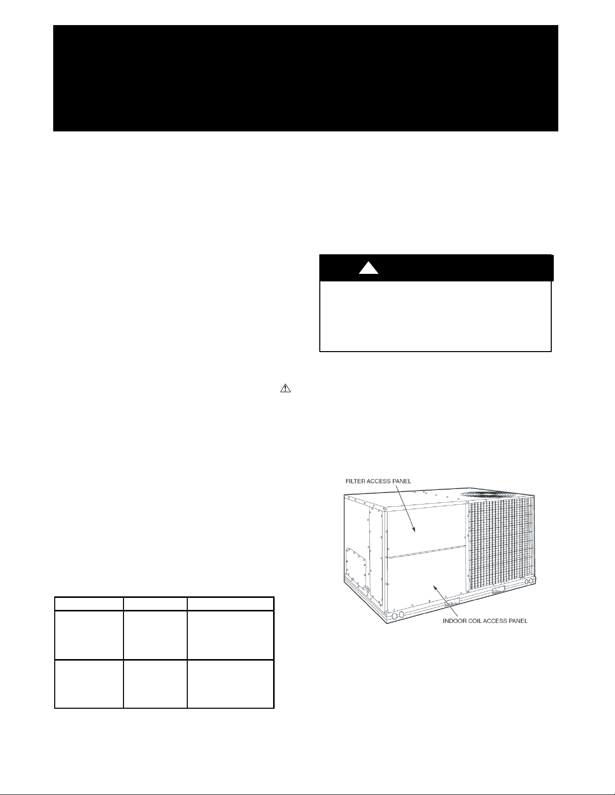
3. Remove filter access panel by raising panel and swinging
panel outward. Panel is now disengaged from track and can
be removed. No tools are required to remove filter access
panel. Remove the outdoor--air opening/indoor coil access
panel. (See Fig. 1.)
C07340
Fig. 1 -- Rooftop Unit Panels
(2--6 ton unit shown)
4. Assemble outside--air hood top, sides and divider as shown
in Fig. 2. Do not install hood at this time.
5. Install galvanized, insulated bottom panel per Fig. 3, with
the slot at the top of the panel. The lip of the slot should fit
behind the corner post as shown. Screw in place.
2
C07341
Fig. 2 -- Damper Hood Panels
C07342
Fig. 3 -- Damper and Hood Panel Installation
6. Adjust the actuator limiter to limit the maximum open
position of the damper to the amount of desired ventilation
air from step 2. The adjustment is made by setting the set
screw on the end of the actuator to the desired position.
Tighten screw firmly to hold in place. (See Fig. 5--7.)
Adjustments can be made after the assembly is installed, by
removing rooftop unit’s horizontal return panel and
accessing the actuator.
7. Lift damper assembly and set in place over the top of the
bottom panel, per Fig. 3. Secure the damper assembly in
place with provided screws.
8. Remove the jumper plug shipped attached to the
economizer harness in the HVAC unit. DO NOT
DISCARD. Connect the plug from the damper actuator
assembly to the economizer plug in the HVAC unit. Set the
jumper plug aside in case it is determined at a later date that
the two position damper is no longer required, at which
time the jumper plug can be reinstalled.
C07343
Fig. 4 -- Filter Installation
C07344
Fig. 5 -- Actuator Limit Screw
9. Install the assembled outside--air hood onto the HVAC unit,
covering the damper assembly. Screw in place.
10. Install the provided aluminum filter into the hood. Lock in
place with top filter clips. (See Fig. 4.)
11. Replace the top filter access panel.
12. Remove lockout tag and restore base unit to operation.
3
0
0.1
0.2
0.3
0.4
0.5
0.6
0.7
0.8
0 500 1,000 1,500 2,000 2,500 3,000
Outdoor Airflow (CFM)
0.4 0.5 0.6 0.7 0.8 0.9
C07363
Fig. 6 -- Actuator Limit Screw Setting (2--6 Ton Units)
CRTWOPOS010A00
0.0
0.1
0.2
0.3
0.4
0.5
0.6
0.7
0.8
0 1,000 2,000 3,000 4,000 5,000 6,000
Airflow (CFM)
0.4 0.5 0.6 0.7 0.8 0.9
C07364
Fig. 7 -- Actuator Limit Screw Setting (7.5--12.5 Ton Units)
CRTWOPOS011A00
4
SEQUENCE OF OPERATION
Cooling
When the room thermostat calls for cooling, the compressor
contactor no. 1 is energized to start compressor no. 1 and
outdoor--fan motor(s). The indoor--fan motor is energized and the
two--position damper moves to its field--adjusted position. On a
further call for cooling, compressor contactor no. 2 is energized
starting compressor no. 2 (7--1/2 to 12--1/2 ton units only). When
the indoor--fan motor is de--energized, the two position damper
moves to the fully closed position.
Heating
When the room thermostat calls for heating, the heating controls
are energized as described in the base unit installation, start--up and
service instructions. The indoor--fan motor is energized and the
two--position damper moves to the set position. When the
indoor--fan motor is de--energized, the two--position damper moves
to the fully closed position.
Ventilation (Continuous Fan)
The two--position damper remains at set position as long as the
indoor fan is energized. When the indoor fan is cycled off, the
two--position damper moves to the fully closed position.
Low Temperature Lockout (Optional)
If desired, a temperature lockout switch can be field installed to
over ride the damper signal and keep it closed if the outside air
temperature falls below a specified air temperature. The
recommended method is to use an outside air lockout switch or
thermostat to make/break the red wire on the damper actuator
harness.
NOTE: In the event of a power failure or if the disconnect to the
unit is shut off, the damper will close due to the internal spring in
the actuator.
SERVICE
Once each heating or cooling season or as conditions require,
perform the following:
1. Inspect the two--position damper blade to ensure it is clean
and moves freely.
2. Visually verify that the damper opens upon a call for
cooling or heating and shuts when the unit is cycled off.
3. Inspect the actuator limit screw on the damper actuator.
Verify it is still in the desired position, and that it has not
slipped. Adjust as required.
WIRING DIAGRAM
RTU
PL-6
C07345
Fig. 8 -- CRTWOPOS010A00 and CRTWOPOS011A00 Wiring
Copyright 2007 CAC / BDP D7310 W. Morris St. DIndianapolis, IN 46231 Printed in U.S.A. Edition Date: 11/07
Manufacturer reserves the right to change, at any time, specifications and designs without notice and without obligations.
Catalog No:IIK---CRTWOPOS01 ---01
Replaces: 48_50--- 63SI and 48_50--- 64SI

This manual suits for next models

1

Other Carrier Air Conditioner manuals

Carrier Bryant Legacy 114S User manual

Carrier

Carrier Bryant Legacy 114S User manual

Carrier 38HD018 Dimensions and installation guide

Carrier

Carrier 38HD018 Dimensions and installation guide

Carrier 38CKE Manual

Carrier

Carrier 38CKE Manual

Carrier TOSHIBA MMD-UP0241HP-UL User manual

Carrier

Carrier TOSHIBA MMD-UP0241HP-UL User manual

Carrier Transport Air Conditioning Reference guide

Carrier

Carrier Transport Air Conditioning Reference guide

Carrier 48HC D17 Series Installation and user guide

Carrier

Carrier 48HC D17 Series Installation and user guide

Carrier 48SD User manual

Carrier

Carrier 48SD User manual

Carrier 38TH..DL Operation manual

Carrier

Carrier 38TH..DL Operation manual

Carrier G Series Cooling User manual

Carrier

Carrier G Series Cooling User manual

Carrier 53G100HF User manual

Carrier

Carrier 53G100HF User manual

Carrier 40GVC User manual

Carrier

Carrier 40GVC User manual

Carrier 40QSM009DS User manual

Carrier

Carrier 40QSM009DS User manual

Carrier KC Series User manual

Carrier

Carrier KC Series User manual

Carrier 73SC005A1C User manual

Carrier

Carrier 73SC005A1C User manual

Carrier 50GJ006 Dimensions and installation guide

Carrier

Carrier 50GJ006 Dimensions and installation guide

Carrier 53KHRT 12-18-24 Crystal User manual

Carrier

Carrier 53KHRT 12-18-24 Crystal User manual

Carrier AIRSTREAM 42BHE Operation manual

Carrier

Carrier AIRSTREAM 42BHE Operation manual

Carrier 40MAQ User manual

Carrier

Carrier 40MAQ User manual

Carrier 42KZL012NS User manual

Carrier

Carrier 42KZL012NS User manual

Carrier 24ABC6 Quick start guide

Carrier

Carrier 24ABC6 Quick start guide

Carrier 48TF004-007 Dimensions and installation guide

Carrier

Carrier 48TF004-007 Dimensions and installation guide

Carrier 40MAQ User manual

Carrier

Carrier 40MAQ User manual

Carrier 40MBFQ243 User manual

Carrier

Carrier 40MBFQ243 User manual

Carrier WeatherMaster 50HC14 User manual

Carrier

Carrier WeatherMaster 50HC14 User manual

Popular Air Conditioner manuals by other brands

Toshiba RAS-10JKCVP Series owner's manual

Toshiba

Toshiba RAS-10JKCVP Series owner's manual

McQuay CC10CW/MCC010CW installation manual

McQuay

McQuay CC10CW/MCC010CW installation manual

Panasonic CS-UW9GKE Service manual

Panasonic

Panasonic CS-UW9GKE Service manual

Jocel JCA002105 instruction manual

Jocel

Jocel JCA002105 instruction manual

Lennox MPA018S4M-*P installation instructions

Lennox

Lennox MPA018S4M-*P installation instructions

LG SW362H8 NRP0 owner's manual

LG

LG SW362H8 NRP0 owner's manual

camry CR 7929 user manual

camry

camry CR 7929 user manual

Brandson Equipment 305041 user manual

Brandson Equipment

Brandson Equipment 305041 user manual

Daikin FXMQ-P7 Technical data

Daikin

Daikin FXMQ-P7 Technical data

Waeco Coolair CA850S installation manual

Waeco

Waeco Coolair CA850S installation manual

Vertiv Liebert XDP user manual

Vertiv

Vertiv Liebert XDP user manual

Hyundai H-AR5-09H-UI025/I instruction manual

Hyundai

Hyundai H-AR5-09H-UI025/I instruction manual

Sanyo KS2432A instruction manual

Sanyo

Sanyo KS2432A instruction manual

Klarstein Metrobreeze New York 7K user manual

Klarstein

Klarstein Metrobreeze New York 7K user manual

Mitsubishi Electric PUZ-HA NHA4 Series installation manual

Mitsubishi Electric

Mitsubishi Electric PUZ-HA NHA4 Series installation manual

LG AK-Q2408C00 owner's manual

LG

LG AK-Q2408C00 owner's manual

LG Art Cool LMAN127HVT Information

LG

LG Art Cool LMAN127HVT Information

Truma Aventa compact operating instructions

Truma

Truma Aventa compact operating instructions

manuals.online logo
manuals.online logoBrands
  • About & Mission
  • Contact us
  • Privacy Policy
  • Terms and Conditions

Copyright 2025 Manuals.Online. All Rights Reserved.