7
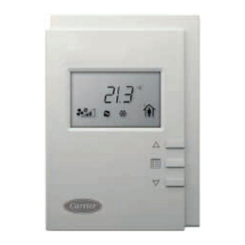
Install the sensor as follows (see Fig. 8):
1. Locate the two Allen type screws at the bottom of the
sensor.
2. Turn the two screws clockwise to release the cover from
the sensor wall mounting plate.
3. Lift the cover from the bottom and then release it from
the top fasteners.
4. Feed the wires from the electrical box through the open-
ing in the center of the sensor mounting plate.
5. Using two no. 6-32 x 1 mounting screws (provided with
the sensor), secure the sensor to the electrical box.
NOTE: Sensor may also be mounted directly on the wall
using 2 plastic anchors and 2 sheet metal screws
(field-supplied).
6. Use 20 gage wire to connect the sensor to the controller.
The wire is suitable for distances of up to 500 ft. Use a
three-conductor shielded cable for the sensor and set
point adjustment connections. The standard CCN com-
munication cable may be used. If the set point adjustment
(slidebar) is not required, then an unshielded, 18 or
20 gage, two-conductor, twisted pair cable may be used.
The CCN network service jack requires a separate,
shielded CCN communication cable. Always use sepa-
rate cables for CCN communication and sensor wir-
ing. (Refer to Fig. 9 and 10 for wire terminations.)
7. Replace the cover by inserting the cover at the top of
the mounting plate first, then swing the cover down
over the lower portion. Rotate the two Allen head
screws counterclockwise until the cover is secured to
the mounting plate and locked in position.
8. For more sensor information, see Table 1 for ther-
mistor resistance vs temperature values.
NOTE: Clean sensor with damp cloth only. Do not use
solvents.
Wiring the Space Temperature Sensor — To wire the sensor,
perform the following (see Fig. 9 and 10):
1. Identify which cable is for the sensor wiring.
2. Strip back the jacket from the cables for at least 3-inches.
Strip 1/4-in. of insulation from each conductor. Cut the
shield and drain wire from the sensor end of the cable.
3. Connect the sensor cable as follows:
a. Remove the factory-installed wire between the ter-
minals labelled SPT and the return air sensor.
b. Connect one wire from the cable (RED) to the SPT
terminal on the controller. Connect the other end of
the wire to the left terminal on the SEN terminal
block of the sensor.
c. Connect another wire from the cable (BLACK) to
the GND terminal on the controller. Connect the
other end of the wire to the remaining open
terminal on the SEN terminal block (COM on
33ZCT57SPT).
d. Connect the remaining wire (WHITE/CLR) to the
T56 terminal on the controller. Connect the other
end of the wire to the SET terminal on the sensor.
e. In the control box, install a no. 10 ring type crimp
lug on the shield drain wire. Install this lug under
the mounting screw of the fan coil controller.
f. On 33ZCT55SPT or 33ZCT56SPT thermostats
install a jumper between the two center terminals
(right SEN and left SET). See Fig. 9.
g. On 33ZCT57SPT thermostats, a separate 3-
conductor, shielded cable is used to connect the fan
speed wiring. Connect the SPD terminal on the
thermostat to the SPEED terminal on the fan coil
controller. Use the white/clr wire. Connect the
COM terminal on the thermostat to the GND ter-
minal on the fan coil controller. Use the black wire.
Connect the 10V terminal on the thermostat to the
+10V terminal on the fan coil controller. Use the
red wire.
In the control box, install a no. 10 ring type crimp
lug on the fan speed wiring shield drain wire.
Install this lug under the mounting screw of the fan
coil controller.
Wiring the CCN Network Communication Service Jack —
See Fig. 9 and 10. To wire the service jack, perform the
following:
1. Strip back the jacket from the CCN communication
cable(s) for at least 3 inches. Strip 1/4-in. of insulation
from each conductor. Remove the shield and separate the
drain wire from the cable. Twist together all the shield
drain wires and fasten them together using an closed end
crimp lug or a wire nut. Tape off any exposed bare wire to
prevent shorting.
2. Connect the CCN + signal wire(s) (RED) to Terminal 5.
3. Connect the CCN – signal wire(s) (BLACK) to
Terminal 2.
4. Connect the CCN GND signal wire(s) (WHITE/CLR) to
Terminal 4.
Before wiring the CCN connection, refer to the Connect the
CCN Communication Bus section on page 13, for communica-
tion bus wiring and cable selection. The cable selected must be
identical to the CCN communication bus wire used for the
entire network.
The other end of the communication bus cable must be con-
nected to the remainder of the CCN communication bus. If the
cable is installed as a T-tap into the bus, the cable length cannot
exceed 50 ft. No more than 10 T-taps are allowed per bus. Wire
the CCN service jack of the sensor in a daisy chain arrange-
ment with other equipment. Refer to the Connect to the CCN
Communication Bus section, page 13, for more details. See
Fig. 11.
Table 1 —Thermistor Resistance vs Temperature Values for Space Temperature Sensor, Return-Air
Temperature Sensor, and Supply-Air Temperature Sensor
TEMP (C) TEMP (F) RESISTANCE (Ohms) TEMP (C) TEMP (F) RESISTANCE (Ohms)
–40 –40 335,651 20 68 12,494
–35 –31 242,195 25 77 10,000
–30 –22 176,683 30 86 8,056
–25 –13 130,243 35 95 6,530
–20 –4 96,974 40 104 5,325
–15 5 72,895 45 113 4,367
–10 14 55,298 50 122 3,601
–5 23 42,315 55 131 2,985
0 32 32,651 60 140 2,487
5 41 25,395 65 149 2,082
10 50 19,903 70 158 1,752
15 59 15,714
