Cartft FLEETPC-4-F User manual

UserManual
0
FleetPC-4-F
In-Vehicle Computing
User Manual
V0.1

UserManual 1

UserManual
2
CARTFT.COM
UserManual
Copyright
©2022byCARTFT.COMAllRightsReserved.
Nopartofthispublicationmaybereproduced,transcribed,storedinaretrievalsystem,translatedinto
anylanguage,ortransmittedinanyformorbyanymeanssuchaselectronic,mechanical, magnetic,
optical, chemical, photocopy, manual, or otherwise, without priorwrittenpermissionfrom
CARTFT.COM
Other brands and product names used herein are for identification purposes only and may be
trademarksoftheirrespectiveowners.
Disclaimer
CARTFT.COM shall not be liable for any incidental or consequential damages resulting from the
performanceoruseofthisproduct.
CARTFT.COMmakesnorepresentationorwarrantyregardingthecontentofthismanual.Information
in this manual had been carefully checked for accuracy; however,noguaranteeisgiventothe
correctnessofthecontents.Forcontinuingproductimprovement,CARTFT.COMreservestherightto
revisethemanualormakechangestothespecificationsofthisproductatanytimewithoutnoticeand
obligationtoanypersonorentityregardingsuchchange.Theinformationcontainedinthismanualis
providedforgeneralusebycustomers.
DeclarationofConformity
TheCEsymbolonyourproductindicatesthatitcomplieswiththeUnionEuropean
(EU) directives. A Certificate of Compliance is available by contacting Technical
Support.ThisproducthaspassedtheCEtestforenvironmentalspecificationswhen
shielded cables are used for external wiring. We recommend the use of shielded
cables.
This product has been tested and found to comply with the limits for a Class B
device,accordingtoPart15oftheFCCRules.Theselimitsare designed toprovide
reasonableprotectionagainstharmfulinterferenceinaresidentialinstallation.This
equipment generates, uses, and can radiate radio frequency energy and, if not
installed and used by the manufacturer’s instructions, may cause harmful
interferencetoradiocommunications.
UserManual 3
Trademarks
CARTFT.COMisaregisteredtrademarkofCARTFT.COM
All the trademarks, registrations, and brands mentioned herein are used for identification purposes
onlyandmaybetrademarksandregisteredtrademarksoftheirrespectiveowners.
SafetyInformation
ReadthefollowingprecautionsbeforesettingupaCARTFT.COMProduct.
Electricalsafety
Topreventelectricalshockhazards,disconnectthepowercablefromtheelectricaloutlet
beforerelocatingthesystem.
Whenaddingorremovingdevicestoorfromthesystem,ensurethatthepowercablesfor
thedevicesareunpluggedbeforethesignalcablesareconnected.Ifpossible,disconnectall
powercablesfromtheexistingsystembeforeaddingadevice.
Beforeconnectingorremovingsignalcablesfromthemotherboard,ensurethatallpower
cablesareunplugged.
Seek professional assistance before using an adapter or extension cord. These devices
couldinterruptthegroundingcircuit.
Ensurethatyourpowersupplyissettothecorrectvoltageinyourarea.Ifyouarenotsure
aboutthevoltageoftheelectricaloutletyouareusing,contactyourlocalpowercompany.
Ifthepowersupplyisbroken,donotfixitbyyourself.Contactaqualifiedservicetechnician
oryourretailer.
Operationsafety
Before installing the motherboard and adding devices, carefully read all the manuals that
camewiththepackage.
Beforeusingtheproduct,ensureallcablesarecorrectlyconnectedandthepowercables
arenotdamaged.Ifyoudetectanydamage,contactyourdealerimmediately.
Keeppaperclips,screws,andstaplesawayfromconnectors,slots,sockets,andcircuitryto
avoidshortcircuits.
Avoid dust, humidity, and temperature extremes. Please do not place the product in any
areawhereitmaybecomewet.
Placetheproductonastablesurface.
Ifyouencountertechnicalproblemswiththeproduct,contactaqualifiedservicetechnician
oryourretailer.

UserManual
4
Environmentalsafety
Usethisproductinenvironmentswithambienttemperaturesbetween‐30˚Cand60˚C.
Donotleavethisproductinanenvironmentwherethestoragetemperaturemaybebelow
‐30°C or above 85°C. To prevent damages, the product must be used in a controlled
environment.
CAUTION
Incorrectlyreplacingthebatterymaydamagethiscomputer.Replaceonlywith
the same or equivalent as recommended by CARTFT.COM Dispose ofused
batteryaccordingtothemanufacturer'sinstructions.
TechnicalSupport
Pleasedonothesitatetocallore‐mailourcustomerservicewhenyoucannotfix
theproblems.
–
TEL:+4971213878264
FAX:+4971213878265
E‐mail:[email protected]
Website:www.CarTFT.com

UserManual 5
TABLEOFCONTENTS
1.0 PRODUCTINTRODUCTION.............................................................................................11
1.1 OVERVIEW.........................................................................................................................11
1.2 KEYFeatureS......................................................................................................................11
1.3 Specification.......................................................................................................................12
1.4 PackageContents..............................................................................................................15
1.5 OrderingInformation.........................................................................................................15
1.6 OptionalAccessory............................................................................................................16
2.0 SYSTEMI/O...................................................................................................................19
2.1 FrontPANELInformation...................................................................................................19
2.1.1 PowerButton...................................................................................................19
2.1.2 LEDIndicators..................................................................................................19
2.1.3 SIMCARDS.......................................................................................................20
2.1.4 USBConnectors...............................................................................................20
2.1.5 HDMI................................................................................................................21
2.1.6 SERIALPORT(OptionalformodelFLEETPC‐4‐F‐2S)..............................................21
2.1.7 DIO...................................................................................................................22
2.2 REARPANELInformation...................................................................................................2 2
2.2.1 AudioJacks.......................................................................................................22
2.2.2 DvI....................................................................................................................2 3
2.2.3 LAN...................................................................................................................23

UserManual 6
2.2.4 DCInputTerminalBlock..................................................................................24
2.3 Illustration........................................................................................................26
2.3.1 System..............................................................................................................26
2.3.2 MainBoard......................................................................................................28
2.4 I/OConnectorDefinition.................................................................................29
2.4.1 AudioConnector..............................................................................................29
2.4.2 LANConnector.................................................................................................29
2.4.3 USB3.0_1/2Connector...................................................................................29
2.4.4 USB2.0_1/2Connector...................................................................................29
2.4.5 COM1/2Connector(OptionalformodelFLEETPC‐4‐F‐2S)..................................30
2.4.6 SIMConnector.................................................................................................30
2.4.7 DIOConnector.................................................................................................30
2.4.8 DCPowerConnector........................................................................................31
2.4.9 HDMIConnector..............................................................................................31
2.4.10 DVI‐DConnector..............................................................................................31
2.5 BoardConnectorDefinition...............................................................................................3 2
2.5.1 NGFF1SLOT(PCI‐E&USB2.0).........................................................................32
2.5.2 NGFF2SLOT(USB3.0&USB2.0).....................................................................33
2.5.3 NGFF3Slot(SATA)............................................................................................34
2.5.4 MiniCard1(PCIe/SATA/USB2.0)......................................................................35
2.5.5 UPSJSTconnector(PCI‐Ex4/SATAx1)..............................................................36
2.5.6 MCUJSTconnector..........................................................................................36

UserManual 7
2.5.7 BATConnector.................................................................................................36
2.5.8 DIOJSTconnector............................................................................................37
2.5.9 COMJSTConnector(RS‐232/422/485)(OptionalformodelFLEETPC‐4‐F‐2S).....37
2.5.10 RemoteBTNconnector(OPTIONAL)...............................................................37
3.0 SYSTEMSETUP..............................................................................................................40
3.1 OpeningtheChassis...........................................................................................................40
3.2 InstallingMemory..............................................................................................................42
3.3 InstallingMiniPCIeExpansionCard(PCIe/SATA/USB2.0).................................................43
3.3 InstallingM.2PCIeSSD....................................................................................................438
3.3 InstallingBAT‐3000‐PBackupBattery(Optional)............................................................439
4.0 SYSTEMRESOURCE.....................................................................................................400
4.1 DIOControlRegister........................................................................................................504
4.2 IgnitionPowerManagementQuickGuide......................................................................515
5.0 BIOSSETTING..............................................................................................................566
5.1 EnterTheBIOS.................................................................................................................566
5.2 Main.................................................................................................................................588
5.3 Advanced.........................................................................................................................598
5.3.1 CPUConfiguration.........................................................................................598
5.3.2 ACPISettings..................................................................................................609
5.3.3 SuperI/O..........................................................................................................51
5.3.4 CMSConfiguration.........................................................................................643
5.4 Chipset.............................................................................................................................654

UserManual 8
5.4.1 PCH‐IOExpressConfiguration........................................................................654
5.4.2 SATA...............................................................................................................665
5.4.3 GraphicsConfiguration..................................................................................699
5.4.4 SystemAgent(SA)Configuration...................................................................722
5.5 Boot..................................................................................................................................734
5.6 Save&Exit.........................................................................................................................64

UserManual
9
Chapter 1
Product Introduction

UserManual 10

UserManual
11
1.0 PRODUCT INTRODUCTION
1.1 OVERVIEW
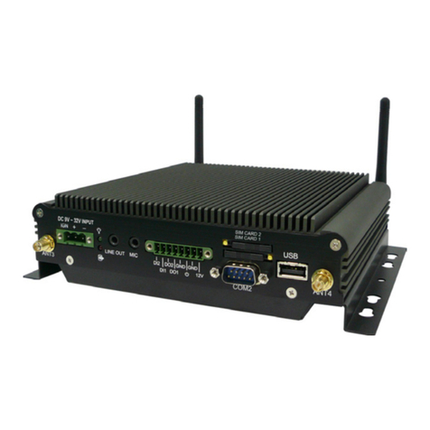
FLEETPC‐4‐Fisanultra‐compactsizefanlessIn‐VehicleComputerwith5Gconnectivity.It
utilizesIntelATOMBraswellN3060Dual‐CoreCPUupto2.48GHz.FLEETPC‐4‐Ffeaturesan
ultra‐compact design measuring 150 x 135 x55.3 mm, easily fittinginto restricted spaces.
Thesystemcanselect5G,LTE,GPS,andWi‐Fi/BTbyM.2modulesasrobustconnectivity.In
addition, it is building‐in DVI‐D, HDMI, audio line out, and microphone in, which is the
perfect solution for fleet management, in‐vehicle digital signage, and mobile DVR.
Furthermore, it features Smarter Vehicle Power Ignition and wireless remote control in
variousvehicles.FLEETPC‐4‐Fcaneffectivelysupportcarsinextremeweatherandoperating
conditions,such as Snowplow,Trucks,Buses,Taxis,andForklifts.CombiningIntelBraswell
N3060CPU,5G,LTE,Wi‐Fi,Bluetoothwirelessconnectivity,andultra‐compactenclosure,
CarTFT.com'FLEETPC‐4‐FisacompactyetversatileIn‐vehiclecomputerthatcanfuelvarious
transportationsystems.
1.2 KEYFEATURES
IntelN3060CoreCPUupto2.48GHz
Wirelesssupport5G/LTE/GPS,Wi‐Fi+Bluetooth(byoptionalM.2modules)
9V~60VDCPowerInput
Smartervehiclepowerignitionforvariousvehicleapplications
Ultra‐compactdesign150x135x55.3mm

UserManual 12
Batterybackup(Optional)
1.3 SPECIFICATION
System
CPU IntelN3060Dual‐CoreCPUupto2.48GHz
Chipset N/A
Memory 1xDDR3L‐1600SO‐DIMMupto8GB
Graphic IntelHDGraphics
LanChipset 1xInteli210ATGigabitEthernet
Watchdog 1~255LevelReset
TPM 2.0
I/O
USBPort 2x3.2Gen1x1
2xUSB2.0
LAN 1xRJ45PortsforGbE
VideoPort 1xHDMI
1xDVI‐D*UseonlywithSingleLinkDVICables
DIOPort
2xAnalogInput(9~60V)
4xDI(5V~60V)
4xDO(5V/100mA/port)
Audio 1xMic‐in,1xLine‐out
ExpansionBus
1xM.23042/3052BKeyforLTE/5Gmodule
1xM.22230A‐EKeyforWi‐Fi+Bluetooth
1xminiPCIeslotsupport(USB+PCIebusormSATA)
Antenna 7xPre‐cutSMAholesforAntennaConnectors
SIMCardSocket 2xSIMCardSocketsSupportedOnboard
SerialPort 2xRS232/422/485(OptionalformodelFLEETPC‐4‐F‐2S)
Storage

UserManual 13
Type
1xM.22280MkeysupportSATABus
*Additional heat sink is required. Please contact a sales representative for more
informationonasuitablemodel.
OperatingSystem
Windows Windows10
Linux Ubuntu16.04
Environment
OperatingTemp. ‐30~60ºC,ambientw/0.6m/sairflow
StorageTemp. ‐30~85ºC
RelativeHumidity 10%RH~90%RH(non‐condensing)
Vibration(withSSD) IEC60068‐2‐64,random,2.5G@5~500Hz,1hr/axis
MIL‐STD‐810G,Method514.6,ProcedureI,Cat.4,Operating
Shock Operating:MIL‐STD‐810G,Method516.6,ProcedureI,
Trucksandsemi‐trailers=15G(11ms)withM.2SSD
Certifications CE,FCCClassA,E13,ECER118
Patent No.M447854Build‐inBattery(Taiwan)
Power
PowerInput 9~60VDCPowerInput
PowerManagement VehiclePowerIgnitionforVarietyVehicle
PowerOffControl PoweroffDelayTimeSettingbyBIOSandSoftware
PowerOffControl PoweroffDelayTimeSettingbySoftwareandBIOS
Battery(UPS)
InternalBatteryKitfor10MinsOperating(Optional)
*UPSbackuptimevariesdependingonactualoverallsystempowerconsumption.
PatentNo.M447854‐Build‐inBattery
Mechanical
Construction AluminumAlloy
Mounting Wall‐mountandVESAmount
Weight 1100g
Dimension 150(L)x135(W)x55.3(H)mm

UserManual 14

UserManual 15
1.4 PACKAGECONTENTS
Yourproductpackageshouldincludetheitemslistedbelow.Ifanyoftheitemsbelowismissing,
contactthedistributorordealerfromwhomyoupurchasedtheproduct.
Item Description Function Q’ty
326910039661 CABLINGMC101‐508‐03GF90D TerminalblockforDCpowerinput
connector 1
351102050110 ScrewITypeM2*5LISO ForfasteningminiPCIemodules 2
372800000900 M.2DataStorageHeatsinkType_3 HeatsinkforDRAMandM.2Modem 1
265066022010 ThermalPAD66x22x1.75Tmm Thermalpadforstickingon(372800000900)
heatsinkforDRAM 1
265016037010 ThermalPAD16x37x1.0Tmm Thermalpadforstickingonthesideof
(372800000900)heatsink 1
351103060810 ROUNDHANDSCREWW/SPRING_P3x6L Forfastening(372800000900),heatsink 1
351125100110 ScrewITypeM2.5x10L Forfastening(372800000900),heatsink 2
351125050110 ScrewITypeM2.5x5L ForfasteningM.2modules 3
370831310200 FLEETPC‐4‐Fmountbracket Forwallmountbracket 2
351451060210 ScrewFType#6‐32*6LNi Forfasteningwallmountbracket 4
1.5 ORDERINGINFORMATION
ModelName Description
FLEETPC‐4‐F Intel®CeleronN3060BraswellCPUwith9~60VDCInputIn‐VehicleComputer
FLEETPC‐4‐F‐2S Intel®CeleronN3060BraswellCPUwith9~60VDCInputand2xCOMIn‐VehicleComputer

UserManual 16
1.6 OPTIONALACCESSORY
CARTFT.COMprovidesoptionalaccessoriesasfollows.Pleasegetintouchwithyourdealerorusifyou
needany.
Item OrderNo. Description
DRAM 515002107610 2GBDDR3LWTInnoDiskM3S0‐2GMJCDPC
DRAM 515004107202 4GBDDR3LWTInnoDiskM3S0‐4GMSCDPC
DRAM 515008107610 8GBDDR3LWTInnoDiskM3S0‐8GMSDDPC
DRAM 510500210711 2GBDDR3LWTApacer75.A83E2.G030B
DRAM 510500810710 8GBDDR3LWTApacer75.C93E2.G040B
M.2SSD 525006400020 64GB,‐40~85°C,withDRAMIM2S3338‐064GP
M.2SSD 525012800020 128GB‐40~85°C,withDRAMIM2S3338‐128GP
M.2SSD 525025600020 256GB‐40~85°C,withDRAMIM2S3338‐256GP
M.2SSD 525051200020 512GB‐40~85°C,withDRAMIM2S3338‐512GP
M.2SSD 525100000020 1TB‐40~85°C,withDRAMIM2S3338‐1TP
5G 570010042001 5GSIM8202GM.2Card‐SIMCom
5GAntenna 342630000000 Antenna5GNRSub6SMAMale
PigtailforModem 341620212001 21cmM.2pigtailcableSMAF‐F
LTE 587906140010 LTE4GCat6SIM7906EM.2Cardkit
CANBUS 580011022000 EMUC‐B202‐W1‐D81JKit
GPS 610810080000 VDB‐810kit
GPS 610810080001 VDB‐810Gkit
GPS 618100080000 VDB‐810DRkit
Wi‐Fi+BT 580261090010 WNFQ‐261ACNI(BT)kit
Batterybackup 580016011001 BAT‐3000‐Pkit
*PleasecheckwithCARTFT.COM’salesrepresentativesfortheavailability.

UserManual
17
Chapter 2
I/O and Connectors

UserManual 18

UserManual
19
2.0 SYSTEMI/O
2.1 FRONTPANELINFORMATION
2.1.1 POWERBUTTON
REDLight:Standby
BLUELight:PowerOn
2.1.2 LEDINDICATORS
ACC
Flash:Detection
Continue:IgnitionReady
SystemStatus
ON:Systemon
OFF:Systemoff
HDD
Flash:OneofStorageRead/Write
UPS
ON:UPSenables
This manual suits for next models
1
Table of contents
Other Cartft Automobile Accessories manuals

Cartft
Cartft FLEETPC-8-I7BPOE User manual

Cartft
Cartft FleetPC-4-B User manual

Cartft
Cartft FleetPC-5-B User manual

Cartft
Cartft FleetPC-2 User manual

Cartft
Cartft FleetPC-5-B User manual

Cartft
Cartft FLEETPC-ARM-300 User manual

Cartft
Cartft FleetPC-11 Series User manual

Cartft
Cartft FleetPC-2 User manual

Cartft
Cartft CALU-MC User manual

Cartft
Cartft FLEETPC-ARM-300 User manual