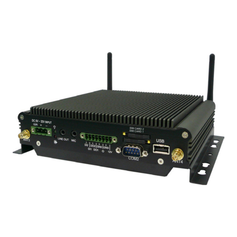
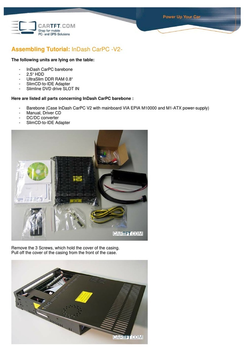
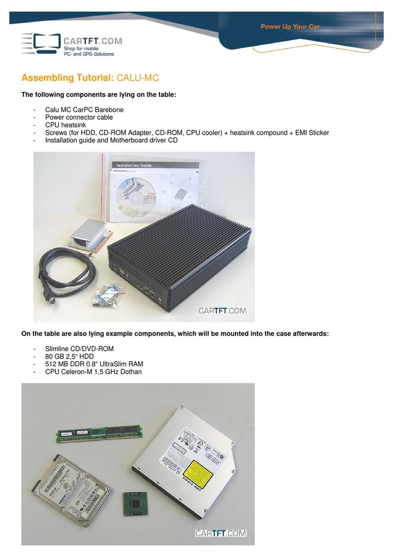
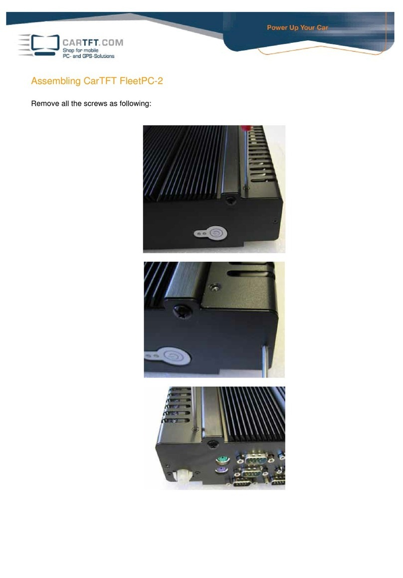
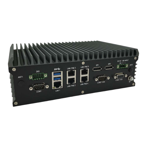
Cartft FLEETPC-8-I7BPOE User manual

FLEETPC-8-I7B-
POE
In-Vehicle Computing
User's Manual
Version 1.2
Document Name FLEETPC-8-I7B-POE User Manual Document No. UM2013361010
Version 1.2 Date Jun. 30, 2015
Reversion History :
Reversion
From To Date Notes Author(s)
1.0 Dec 30, 2014 Initial Document Issued Stanley Chou
1.0 1.1 Feb. 26, 2015 Update Connector and BIOS Stanley Chou
1.1 1.2 Jun. 30, 2015 Replace Mechanical Drawing Stanley Chou

User’s Manual Page i
CarTFT.come.K.
UserManual
Copyright
©2009byCarTFT.come.K..AllRightsReserved.
Nopartofthispublicationmaybereproduced,transcribed,storedinaretrievalsystem,
translatedintoanylanguage,ortransmittedinanyformorbyanymeanssuchas
electronic,mechanical,magnetic,optical,chemical,photocopy,manual,orotherwise,
withoutpriorwrittenpermissionfromCarTFT.come.K..
Otherbrandsandproductnamesusedhereinareforidentificationpurposesonlyand
maybetrademarksoftheirrespectiveowners.
Disclaimer
CarTFT.come.K..shallnotbeliableforanyincidentalorconsequentialdamages
resultingfromtheperformanceoruseofthisproduct.
CarTFT.come.K..makesnorepresentationorwarrantyregardingthecontentofthis
manual.Informationinthismanualhadbeencarefullycheckedforaccuracy;however,
noguaranteeisgivenastothecorrectnessofthecontents.Forcontinuingproduct
improvement,CarTFT.come.K..reservestherighttorevisethemanualormakechanges
tothespecificationsofthisproductatanytimewithoutnoticeandobligationtoany
personorentityregardingsuchchange.Theinformationcontainedinthismanualis
providedforgeneralusebycustomers.
ThisdevicecompliestoPart15oftheFCCRules.Operationissubjecttothefollowing
twoconditions:
1. Thisdevicemaynotcauseharmfulinterference.
2. Thisdevicemustwithstandanybackgroundinterferenceincludingthosethatmay
causeundesiredoperation.

User’s Manual Page ii
SafetyInformation
ReadthefollowingprecautionsbeforesettingupaCARTFT.COME.K.Product.
Electricalsafety
Topreventelectricalshockhazard,disconnectthepower
cablefromtheelectricaloutletbeforerelocatingthesystem.
Whenaddingorremovingdevicestoorfromthesystem,
ensurethatthepowercablesforthedevicesareunpluggedbeforethesignal
cablesareconnected.Ifpossible,disconnectallpowercablesfromtheexisting
systembeforeyouaddadevice.
Beforeconnectingorremovingsignalcablesfromthe
motherboard,ensurethatallpowercablesareunplugged.
Seekprofessionalassistancebeforeusinganadapteror
extensioncord.Thesedevicescouldinterruptthegroundingcircuit.
Makesurethatyourpowersupplyissettothecorrect
voltageinyourarea.Ifyouarenotsureaboutthevoltageoftheelectricaloutlet
youareusing,contactyourlocalpowercompany.
Ifthepowersupplyisbroken,donottrytofixitby
yourself.Contactaqualifiedservicetechnicianoryourretailer.
Operationsafety
Beforeinstallingthemotherboardandaddingdeviceson
it,carefullyreadallthemanualsthatcamewiththepackage.
Beforeusingtheproduct,makesureallcablesare
correctlyconnectedandthepowercablesarenotdamaged.Ifyoudetectany
damage,contactyourdealerimmediately.
Toavoidshortcircuits,keeppaperclips,screws,and
staplesawayfromconnectors,slots,socketsandcircuitry.
Avoiddust,humidity,andtemperatureextremes.Donot
placetheproductinanyareawhereitmaybecomewet.
Placetheproductonastablesurface.
Ifyouencountertechnicalproblemswiththeproduct,
contactaqualifiedservicetechnicianoryourretailer.

User’s Manual Page iii
CAUTION
Incorrectlyreplacingthebatterymaydamagethiscomputer.Replaceonlywiththe
sameoritsequivalentasrecommendedbyCarTFT.come.K..Disposeusedbattery
accordingtothemanufacturer'sinstructions.
TechnicalSupport
Pleasedonothesitatetocallore‐mailourcustomerservicewhenyoustillcannotfix
theproblems.
Website:www.cartft.com

User’s Manual Page iv
TABLEOFCONTENTS
Page #
1.0Introduction ............................................................................................................................... 1-1
1.1ModelSpecification.............................................................................................................. 1-1
1.2FLEETPC‐8‐I7B‐POEIllustration(MB,System) .............................................................. 1-3
1.3Architecture .......................................................................................................................... 1-5
1.4PrincipalcomponentSpecification................................................................................... 1-5
2.0INTERNALCONNECTOR ............................................................................................................ 2-1
2.1VGAConnector(VGA1) ........................................................................................................ 2-1
2.2USBConnector(USB2)......................................................................................................... 2-2
2.3USBConnector(USB1)......................................................................................................... 2-3
2.4GPIOConnector(GPIO1)..................................................................................................... 2-4
2.5LEDConnector(LED1)......................................................................................................... 2-5
2.6LEDConnector(LED2)......................................................................................................... 2-6
2.7LEDConnector(LED3)......................................................................................................... 2-7
2.8LEDConnector(LED4)......................................................................................................... 2-8
2.9COMConnector(COM2) ...................................................................................................... 2-8
2.10COMConnector(COM3) ...................................................................................................... 2-9
2.11COMConnector(COM4) .................................................................................................... 2-10
2.12AUDIOConnector ............................................................................................................... 2-12
2.13SATAConnector(SATA1).................................................................................................. 2-13
2.14SATAConnector(SATA2).................................................................................................. 2-14
2.15MiniPCI‐EConnector(MINICARD1) ............................................................................... 2-15
2.16MiniPCI‐EConnector(MINICARD2) ............................................................................... 2-17
2.17MiniPCI‐EConnector(MINICARD3) ............................................................................... 2-19
2.18MiniPCI‐EConnector(MINICARD4) ............................................................................... 2-21
2.19PowerInputConnector ..................................................................................................... 2-23
2.20UPSPowerConnector........................................................................................................ 2-24
2.21LANConnector(LAN1) ...................................................................................................... 2-25
2.22LANConnector(LAN2) ...................................................................................................... 2-26
2.23LANConnector(LAN3) ...................................................................................................... 2-27
2.24LANConnector(LAN4) ...................................................................................................... 2-28

User’s Manual Page v
3.0ExternalConnectorSpecification............................................................................................ 3-1
3.1M12ConnectingtotheNetwork........................................................................................ 3-1
3.2USBConnector(USB3)......................................................................................................... 3-2
3.3USBConnector(USB4)......................................................................................................... 3-3
3.4DVI‐IConnector .................................................................................................................... 3-4
3.5DPConnector......................................................................................................................... 3-5
3.6COMConnector(COM1) ...................................................................................................... 3-6
3.7MICINConnector.................................................................................................................. 3-7
3.8LINEOUTConnector ............................................................................................................ 3-8
3.9PowerOutConnector .......................................................................................................... 3-9
3.10CANBUSPinAssignment .................................................................................................. 3-10
4.0SystemInstallation ................................................................................................................... 4-1
4.1SystemIntroduction ............................................................................................................ 4-1
4.2OpeningChassis.................................................................................................................... 4-2
4.3InstallingMemory ................................................................................................................ 4-4
4.4InstallingMINIPCIeExpansionCard(PCIe1,3G/LTEModuleonly)......................... 4-6
4.5InstallingMINIPCIeExpansionCard(PCIe2,GPSModuleonly)................................ 4-8
4.6InstallingMINIPCIeExpansionCard(PCIe3) .............................................................. 4-10
4.7InstallingmSATAFlashCard(PCIe4,mSATAonly) .................................................... 4-12
4.8InstallingInternalAntennaCable................................................................................... 4-13
4.9InstallingSIMCard ............................................................................................................. 4-18
4.10InstallingHDD..................................................................................................................... 4-20
4.11InstallingBatteryModule ................................................................................................. 4-22
5.0SystemResource ........................................................................................................................ 5-1
5.1IgnitionPowerManagementQuickGuide....................................................................... 5-1
5.2GPIO&DelayTimeSetting ................................................................................................. 5-3
5.2.1GPIOandIgnitionControlRegister................................................................................................. 5-3
5.2.2WDTSetting...................................................................................................................................... 5-6
6.0BIOS ............................................................................................................................................. 6-1
6.1EnterTheBIOS...................................................................................................................... 6-1
6.2Main ........................................................................................................................................ 6-3
6.3Advanced................................................................................................................................6-4
6.4Chipset.................................................................................................................................. 6-10
6.5Boot ....................................................................................................................................... 6-13
6.6Security ................................................................................................................................6-15
User’s Manual Page vi
6.7Exit ........................................................................................................................................ 6-16
7.0PackingList ................................................................................................................................7-1
7.1PackingList ........................................................................................................................... 7-1

1.0 Introduction
User’s Manual
1.0
INTRODUCTION

1.0 Introduction
User’s Manual Page 1-1
1.0 INTRODUCTION
1.1ModelSpecification
System
CPU
IntelGen4Corei7‐4650U1.7GHzupto3.3GHz
IntelGen4Corei5‐4300U1.9GHzupto2.9GHz
IntelGen4Corei3‐4010U1.7GHz
Memory2xDDR3L1600MHzSO‐DIMMupto16GB
ChipsetQM87
LANChipsetIntelI210‐ATGb/sEthernetControllersOnboard
SupportPXEandWOL
AudioRealtekALC662HDCodeconboard
WatchdogWatchdogTimerSupport,Offer1–255Step
PowerRequirement
PowerInput9V‐36VDCPowerinput
PowerProtectionAutomaticsRecoveryShortCircuitProtection
PowerManagementVehiclePowerIgnitionforVarietyVehicle
PowerOffControlPoweroffDelayTimeSettingbySoftware,Defaultis5Mins
BatteryInternalBatteryKitfor10MinsOperating(Optional)
Storage
Type2x2.5”DriveBayforSATATypeHDD/SSD,SupportRAID0,1
1xMini‐PCIeDOM

1.0 Introduction
User’s Manual Page 1-2
Graphics
Graphics
Intel®HDGraphics5000
DirectXVideoAcceleration(DXVA)forAcceleratingVideo
Processing‐FullAVC/VC1/MPEG2HWDecode
SupportsDirectX11/10.1/10/9andOpenGL4.0
ResolutionUpto4096x2304
Qualification
CertificationsCE,FCCClassA,EMarkCompliance,EN50155,EN50121
I/O
SerialPort4xRS‐232(2withRS‐485(AutoDirectionControl))
USBPort2xUSB3.0Ports,2xUSB2.0Ports
LAN4xM12PortsforGbEPOE(15.4Wperport)
VideoPort
1xDVI‐DConnectoronRearI/O
1xDPPortConnectoronRearI/O
(SupportDualIndependentDisplay)
DIOPort4Inand4Out
Audio1xLine‐outand1xMic‐in(Line‐inOptional)
SIMCardSocket1xSIMCardSocketSupportedOnboardwitheject
Environment
OperatingTemp.‐40ºC~70ºC(DefaultCPU17Watt)
StorageTemp.‐40~80ºC
RelativeHumidity0%RH–95%RH
Vibration(random)2.5g@5~500HzwithSSD
VibrationOperatingMIL‐STD‐810F,Method514.5,Category20,GroundVehicle‐Highway
TruckStorageMIL‐STD‐810F,Method514.5,Category24,IntegrityTest
ShockOperating:MIL‐STD‐810F,Method516.5,ProcedureI,
Trucksandsemi‐trailers=40G(11ms)withSSD
CrashHazardMIL‐STD‐810F,Method516.5,ProcedureV,
Groundequipment=100
Mechanical
ConstructionAluminumalloy
MountingSupportsbothofwall‐mount/VESA‐mount
Weight1.780kg(bare‐bone)
Dimensions250x150x55mm

1.0 Introduction
User’s Manual Page 1-3
1.2 FLEETPC‐8‐I7B‐POEIllustration(MB,System)
MainBoard

1.0 Introduction
User’s Manual Page 1-4
System

1.0 Introduction
User’s Manual Page 1-5
1.3Architecture
1.4PrincipalcomponentSpecification
CPU
Chip Description
Intel 1. Power consumption:
CPU Core Frequency Cache TDP Tj
i7-4650U 1.7 GHz 4MB 15 W 105°C
i5-4300U 1.9 GHz 3MB
15 W 105°C
i3-4010U 1.7 GHz 3MB
15 W 105°C
2980U 1.6 GHZ 2MB
15 W 105°C

2.0 Internal Connector Specification
User’s Manual
2.0
INTERNALCONNECTOR
SPECIFICATION

2.0 Internal Connector Specification
User’s Manual Page 2-1
2.0 INTERNALCONNECTOR
2.1VGAConnector(VGA1)
Connector size 2 X 8 = 16 Pin
Connector type JST-2.0mm-M-180
Connector location VGA1
Connector pin
definition
Pin Signal Pin Signal
1 RED 2 GREEN
3 BLUE 4 NC
5 CER_DET 6 GND
7 GND 8 GND
9 +5V 10 GND
11 NC 12 DAC_SDA
13 HSYNC 14 VSYNC
15 DAC_SCL 16 NC
Connector map

2.0 Internal Connector Specification
User’s Manual Page 2-2
2.2USBConnector(USB2)
Connector size 2 X 4 = 8 Pin
Connector type JST-2.0mm-M-180
Connector location USB2 (Co-layout with DVI-I1)
Connector pin
definition
Pin Signal Pin Signal
1 5VSB 2 5VSB
3 USB_7N 4 NC
5 USB_7P 6 NC
7 GND 8 GND
Connector map

2.0 Internal Connector Specification
User’s Manual Page 2-3
2.3USBConnector(USB1)
Connector size 2 X 4 = 8 Pin
Connector type JST-2.0mm-M-180
Connector location USB1 (Co-layout with MINICARD3)
Connector pin
definition
Pin Signal Pin Signal
1 5VSB 2 5VSB
3 USB_6N 4 NC
5 USB_6P 6 NC
7 GND 8 GND
Connector map

2.0 Internal Connector Specification
User’s Manual Page 2-4
2.4GPIOConnector(GPIO1)
Connector size 2 X 5 = 10 Pin
Connector type JST-2.0mm-M-180
Connector location GPIO1
Connector pin
definition
Pin Signal Pin Signal
1 GPI0 2 GPI1
3 GPI2 4 GPI3
5 GPO0 6 GPO1
7 GPO2 8 GPO3
9 GND 10 +12V
Connector map
Pin Signal
GPIO
1 GPI0
2 GPI1
3 GPI2
4 GPI3
5 GPO0
6 GPO1
7 GPO2
8 GPO3
9 GND

2.0 Internal Connector Specification
User’s Manual Page 2-5
2.5LEDConnector(LED1)
Connector size 2 X 2 = 4 Pin
Connector type LED WITH HOUSING
Connector location LED1
Connector pin
definition
Pin Signal Pin Signal
A1 3.5G_LED_P A2 UPS_LED_P
C1 3.5G_LED_N C2 UPS_LED_N
Connector map

2.0 Internal Connector Specification
User’s Manual Page 2-6
2.6LEDConnector(LED2)
Connector size 2 X 2 = 4 Pin
Connector type LED WITH HOUSING
Connector location LED2
Connector pin
definition
Pin Signal Pin Signal
A1 ACC_LED_P A2 HDD_LED_P
C1 ACC_LED_N C2 HDD_LED _N
Connector map
Table of contents
Other Cartft Automobile Accessories manuals

Cartft
Cartft FleetPC-2 User manual

Cartft
Cartft FLEETPC-ARM-300 User manual

Cartft
Cartft InDash CarPC User manual

Cartft
Cartft FleetPC-11 Series User manual

Cartft
Cartft FleetPC-4-B User manual

Cartft
Cartft FleetPC-5-B User manual

Cartft
Cartft FleetPC-5-B User manual

Cartft
Cartft CALU-MC User manual

Cartft
Cartft FleetPC-8-i7C User manual

Cartft
Cartft FLEETPC-ARM-300 User manual
Popular Automobile Accessories manuals by other brands

Vision X
Vision X LICENSE PLP910 Installation instructions & user manual

Truma
Truma Mover XT operating instructions

Chevrolet
Chevrolet 94729716 manual

ATD Tools
ATD Tools SPI-77300 user manual

PE Racing
PE Racing Pedalbox Assembly Manual & Installation Instructions

Polaris
Polaris RideCommand quick start guide