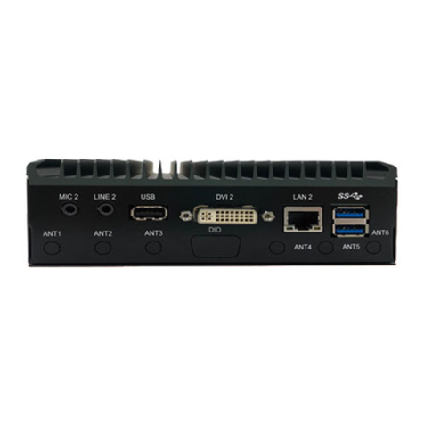
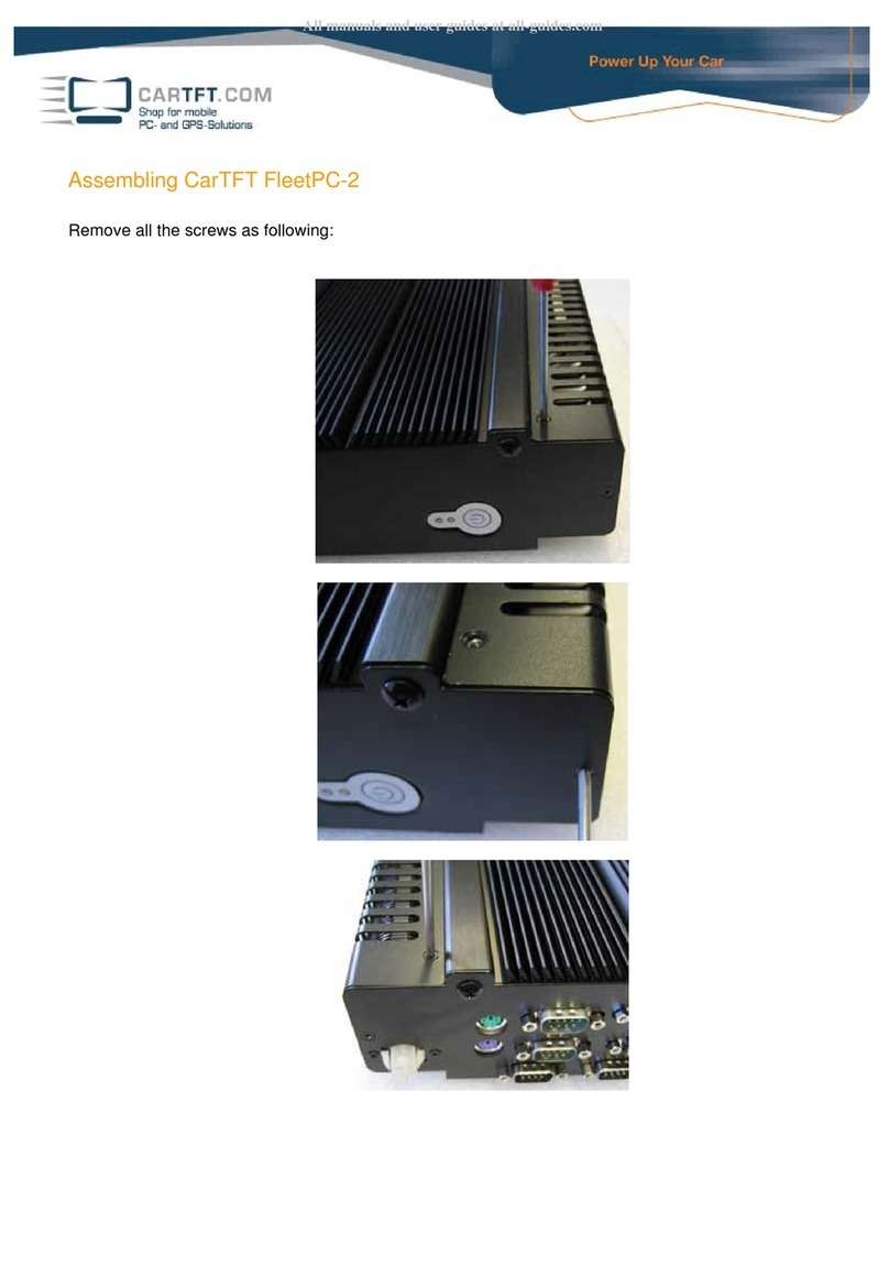
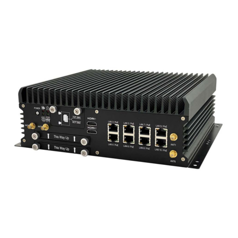
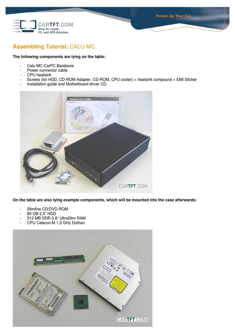
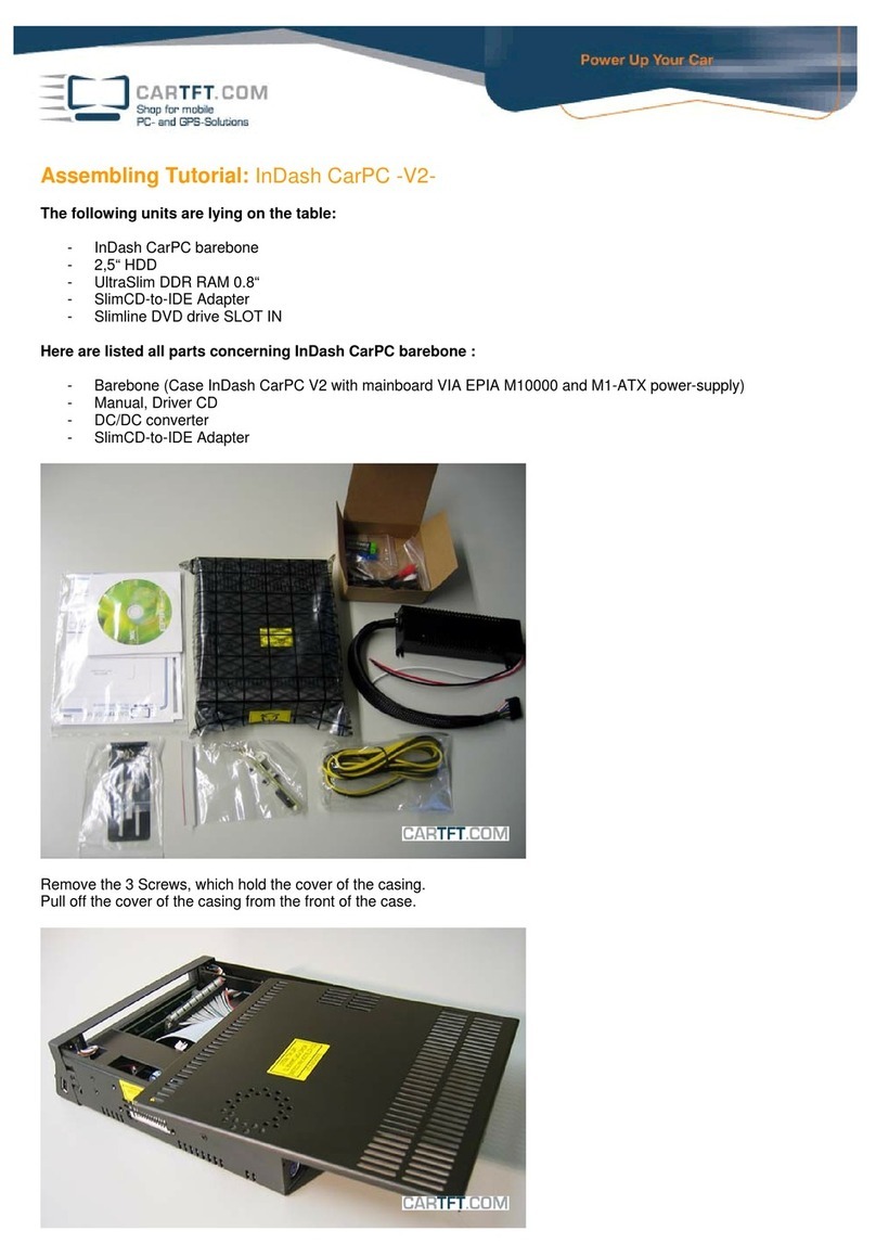
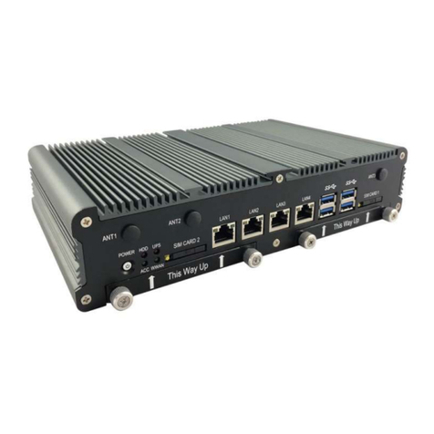
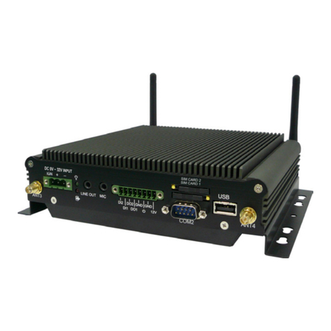
Cartft FleetPC-5-B User manual

FleetPC-5-B
In-Vehicle Computing
User's Manual
Version 1.0
Document Name FleetPC-5-B User Manual Document No. UM2018321010
Version 1.0 Date June 1, 2018
Reversion History :
Reversion Date Notes Author(s)
From To
1.0 1.0 Jane 1 , 2018 Initial document issued Stanley Chou
All manuals and user guides at all-guides.com
all-guides.com

CarTFT.come.K.
UserManual
Copyright
©2009byCarTFT.come.K.AllRightsReserved.
Nopartofthispublicationmaybereproduced,transcribed,storedinaretrievalsystem,
translated into any language, or transmitted in any form or by any means such as
electronic,mechanical,magnetic,optical,chemical,photocopy,manual,orotherwise,
withoutpriorwrittenpermissionfromCarTFT.come.K.
Otherbrandsandproductnamesusedhereinareforidentificationpurposesonlyand
maybetrademarksoftheirrespectiveowners.
Disclaimer
CarTFT.come.K.shallnotbeliableforanyincidentalorconsequentialdamagesresulting
fromtheperformanceoruseofthisproduct.
CarTFT.come.K.makesno representation or warrantyregarding the contentofthis
manual.Informationinthismanualhadbeencarefullycheckedforaccuracy;however,
noguarantee isgiven astothecorrectness ofthecontents. Forcontinuingproduct
improvement,CarTFT.come.K.reservestherighttorevisethemanualormakechanges
tothespecificationsofthisproductatanytimewithoutnoticeandobligationtoany
personorentityregardingsuchchange.Theinformationcontainedinthismanualis
providedforgeneralusebycustomers.
ThisdevicecompliestoPart15oftheFCCRules.Operationissubjecttothefollowing
twoconditions:
1. Thisdevicemaynotcauseharmfulinterference.
2. Thisdevicemustwithstandanybackgroundinterferenceincludingthosethatmay
causeundesiredoperation.
User’s Manual Page 2
All manuals and user guides at all-guides.com

SafetyInformation
ReadthefollowingprecautionsbeforesettingupaCarTFT.comProduct.
Electricalsafety
Topreventelectricalshockhazard,disconnectthepower
cablefromtheelectricaloutletbeforerelocatingthesystem.
Whenaddingorremovingdevicestoorfromthesystem,
ensure that the power cables for the devices are unplugged beforethesignal
cablesareconnected.Ifpossible,disconnectallpowercablesfromtheexisting
systembeforeyouaddadevice.
Beforeconnectingorremovingsignalcablesfromthe
motherboard,ensurethatallpowercablesareunplugged.
Seekprofessionalassistancebeforeusing an adapteror
extensioncord.Thesedevicescouldinterruptthegroundingcircuit.
Makesurethatyourpowersupplyissettothecorrect
voltageinyourarea.Ifyouarenotsureaboutthevoltageoftheelectricaloutlet
youareusing,contactyourlocalpowercompany.
Ifthepowersupplyisbroken,donottrytofixitby
yourself.Contactaqualifiedservicetechnicianoryourretailer.
Operationsafety
Beforeinstallingthemotherboardandaddingdeviceson
it,carefullyreadallthemanualsthatcamewiththepackage.
Beforeusingtheproduct,makesureallcablesare
correctlyconnectedand the powercables are notdamaged. Ifyoudetectany
damage,contactyourdealerimmediately.
Toavoidshortcircuits,keeppaperclips,screws,and
staplesawayfromconnectors,slots,socketsandcircuitry.
Avoiddust,humidity,andtemperatureextremes.Donot
placetheproductinanyareawhereitmaybecomewet.
Placetheproductonastablesurface.
If you encounter technical problems with the product,
contactaqualifiedservicetechnicianoryourretailer.
User’s Manual Page 3
All manuals and user guides at all-guides.com

CAUTION
Incorrectly replacing the battery may damage this computer. Replaceonlywiththe
same or its equivalent as recommended by CarTFT.com e.K. Disposeusedbattery
accordingtothemanufacturer'sinstructions.
TechnicalSupport
Pleasedonothesitatetocallore‐mailourcustomerservicewhenyoustillcannotfix
theproblems.
Tel:+886‐2‐82280101
Fax:+886‐2‐82280100
E‐mail:sales@cartft.com
Website:www.cartft.com
User’s Manual Page 4
All manuals and user guides at all-guides.com

1.0 Introduction
TABLEOFCONTENTS
Page #
1.0Introduction..........................................................................................................................................................8
1.1 Model Specification.........................................................................................................................................8
1.2 VBOX-3210 Illustration (MB, System).........................................................................................................9
1.3 Architecture...................................................................................................................................................13
1.4 Power Consumption.....................................................................................................................................13
2.0Internal Connector Specification.......................................................................................................................15
2.1 Battery Connector (BAT1)...........................................................................................................................15
2.2 COM Port Connector (COM1)....................................................................................................................16
2.3 COM Port Connector (COM2)....................................................................................................................17
2.4 COM Port Connector (COM3)....................................................................................................................18
2.5 COM Port Connector (COM4)....................................................................................................................19
2.6 MCU DOWN Connector..............................................................................................................................20
2.7 DIP Switch Connector..................................................................................................................................21
2.8 SATA Power Connector...............................................................................................................................22
2.9 SATA Connector...........................................................................................................................................23
2.10 USB Connector............................................................................................................................................24
2.11 DEBUG Connector.....................................................................................................................................25
2.12 SPI Connector.............................................................................................................................................26
2.13 UPS Connector............................................................................................................................................27
2.14 VGA Connector...........................................................................................................................................28
2.15 Mini PCI-E Connector (MINICARD1)....................................................................................................29
2.16 Mini PCI-E Connector (MINICARD2)....................................................................................................31
2.17 Mini PCI-E Connector (MINICARD3)....................................................................................................33
2.18 M.2 Connector.............................................................................................................................................35
2.19 CFAST Connector......................................................................................................................................37
3.0External Connector Specification......................................................................................................................39
3.1 Power Input Connector................................................................................................................................39
3.2 DP Connector (DP1).....................................................................................................................................40
3.3 DP Connector (DP2).....................................................................................................................................41
3.4 USB Connector..............................................................................................................................................42
User’s Manual
All manuals and user guides at all-guides.com

1.0 Introduction
3.5 LAN Connector (LAN1)...............................................................................................................................43
3.6 LAN Connector (LAN2)...............................................................................................................................44
3.7 LAN + USB 3.0 Connector...........................................................................................................................45
3.8 DIO Connector..............................................................................................................................................46
3.9 AUDIO Connector........................................................................................................................................47
4.0System Installation..............................................................................................................................................50
4.1 System Introduction.....................................................................................................................................50
4.2 Opening Chassis............................................................................................................................................51
4.3 Installing Memory.........................................................................................................................................53
4.4 Installing MINI PCIe Expansion Card (Minicard 1, 3G/LTE)................................................................55
4.5 Installing MINI PCIe Expansion Card (MiniCard 2)...............................................................................57
4.6 Installing MINI PCIe Expansion Card (MiniCard 3)...............................................................................59
4.7 Installing M.2 Module..................................................................................................................................61
4.8 Installing Internal Antenna Cable...............................................................................................................63
4.9 Installing SIM Card......................................................................................................................................67
4.10 Installing HDD............................................................................................................................................69
4.11 Installing CFast Card Module...................................................................................................................72
4.12 Installing POE Module...............................................................................................................................75
5.0BIOS....................................................................................................................................................................78
5.1 Enter The BIOS............................................................................................................................................78
5.2 Main...............................................................................................................................................................80
5.3 Advanced.......................................................................................................................................................81
5.4 Chipset...........................................................................................................................................................84
5.5 Boot................................................................................................................................................................86
6.0Packing List.........................................................................................................................................................89
6.1 Packing List...................................................................................................................................................89
User’s Manual
All manuals and user guides at all-guides.com
all-guides.com

1.0 Introduction
1.0
INTRODUCTION
User’s Manual
All manuals and user guides at all-guides.com

1.0 Introduction
1.0 INTRODUCTION
1.1 ModelSpecification
System
CPU
AMDRX‐421BDQuadCore2.1GHzupto3.4GHz*
AMDRX‐216GDDualCore1.6GHzupto3.0GHz(OptionalGX‐224IJ,
GX‐215JJ)
*Configto15W
Memory 2xSO‐DIMMDDR4upto32GB(1xSO‐DIMMDDR4forGXseries)
Graphics AMDRadeon™graphics
ATA 2xSerialATAGEN3.0
LANChipset 2xInteli210‐AT;EthernetSwtich:1xMarvell88E6176
Watchdog 1~255LevelReset
PowerRequirement
PowerInput 9V‐48VDCPowerinput
PowerProtection AutomaticsRecoveryShortCircuitProtection
PowerManagement VehiclePowerIgnitionforVarietyVehicle
PowerOffControl PoweroffDelayTimeSettingbyBIOSandSoftware
Battery InternalBatteryKitfor10MinsOperating(Optional)
PatentNo.:M447854‐Build‐inBattery
Storage
User’s Manual Page 8
All manuals and user guides at all-guides.com

1.0 Introduction
Type 1x2.5"DriveBayforSATATypeHDD/SSD
1xCfastslot
Qualification
Certifications CE,FCCClassA,E13
I/O
SerialPort 2xRS232/422/485(optionadditional2xRS232)
USBPort 2xUSB3.0portsand2xUSB2.0Ports
LAN 5xRJ45PortsGbE(Optinalfor4xPOE802.3at/af*)
VideoPort 2xDP(Optionadditional1xVGAforRXseries)
GPIOPort 4Inand4Out
Audio Mic‐in/Line‐out(OptionalLinein)
ExpansionBus 3xMini‐cardslots
1xM.2A‐Ekey2230slot
Antenna Antenna4xSMA‐typeExternalAntennaConnectors
SIMCardSocket SIMCardSocket2xSIMCardSocketsSupportedOnboardwitheject
Environment
OperatingTemp. ‐40ºC~70ºC(w/SSD)
StorageTemp. ‐40ºC~85ºC
RelativeHumidity 5%RH–95%RH
Vibration(random) IEC60068‐2‐64,random,2.5G@5~500Hz,1hr/axiswithSSD
VibrationOperating MIL‐STD‐810G,Method514.6,ProcedureI,Category4
Shock Operating:MIL‐STD‐810G,Method516.6,ProcedureI,Trucksand
semi‐trailers=15G(11ms)withSSD
Mechanical
Construction AluminumAlloy
Mounting Wall‐mount,VESA‐mount,DinRailMountingKit
Weight 1405g(Barebone)
Dimensions 240(L)x161(W)x85(H)mm
1.2 FleetPC‐5‐BIllustration(MB,System)
MainBoard
User’s Manual Page 9
All manuals and user guides at all-guides.com

1.0 Introduction
FrontI/O
User’s Manual Page 10
All manuals and user guides at all-guides.com

1.0 Introduction
RearI/O
System
User’s Manual Page 11
All manuals and user guides at all-guides.com
all-guides.com

1.0 Introduction
User’s Manual Page 12
All manuals and user guides at all-guides.com

1.0 Introduction
1.3 Architecture
EthernetSwitch
Marvell88E6176
MDIBUS RJ45
PORT2(PoE)
RJ45
PORT3(PoE)
MDIBUS
RJ45
PORT4(PoE)
RJ45
PORT5(PoE)
MDIBUS
MDIBUS
MiniPCI‐ESlot3
Fullfunction
FullSize
PCI‐EX1#3
MiniPCI‐ESlot2
Fullfunction
FullSize
PCI‐EX1#2
SATA3.0#0
SATAPORT1
CFastcard
SATAPORT0
7PINCON.
SATA3.0#1
UIMBUS
MiniPCI‐ESlot1
3G/LTE
FullSize
USB2.0#1
HDAudio
Realtek
ALC662
HDCodec
MICIN
FRONTOUT
USB2.0#3
USB2.0#2
TPM2.0
Type1DualChannel
Type3SingleChannel(CH‐B)
Type1SupportDP0,1,2
Type3SupportDP0,1
max:16GB
LINEOUT
MICIN
MDIBUS
RS232/422/485
HWMonitor
Volt agemonitor
TEMPSmonitor
SUPERI/O
FINTEK
F81866AD‐I
COMPORT1~4
2x5JST
LPCBUS
SIM1 SIM2
USB2.0#7
USB2.0HUB
DP0
CH7517A‐BF
VGA
JSTCON
VGA
Rseries‐SOC
MerlinFalcon(FP4)
RE421BAAY43KA(Type1)
CPU:4Core
Core:52.6A
NB:13.1A
GFX:43.6A
TDP:34W
RE216GAAY23KA(Type1)
CPU:4Core
Core:26.6A
NB:15.0A
GFX:34.7A
TDP:15W
GE224IAVY23AC(Type3)
CPU:2Core
Core:25.3A
NB:17.0A
GFX:NA
TDP:15W
GE215JAWY23AC(Type3)
CPU:2Core
Core:10.8A
NB:13.5A
GFX:NA
TDP:10W
GPIO4in/4out
2x5TerminalBlock
GPIO
RJ45
PORT1
USB2.0#0
GFX#7
M.2
A‐Ekey
USB2.0HUB#0~1
USB2.0
PORT1~4
USB2.0#4/#5
USB3.0
PORT1~2
SPIROM
64Mb
SPI
UIMBUS
AMD
PoEisoptional
LINEIN
LINEIN
DDR4BUS
SO‐DIMMDDR42400MHz
DUAL‐CH
DisplayPort1
DP1
DisplayPort2
DP2
968‐BALLBGA
29X37mm
PCI‐EX1#0
Intel
WGI210AT
GBE
Intel
WGI210AT
GBE
PCI‐EX1#1 MDIBUS
1.4 PowerConsumption
Chip Description
Intel Power consumption:
CPU Cores Core
Frequency L2 Cache TDP Tj
RX-421BD 4 2.1 GHz 2MB 12~35W 105°C
RX-216GD 2 1.6 GHz 1MB 12~15W 105°C
GX-224IJ 2 2.4 GHz 1MB 10~15W 105°C
GX-215JJ 2 1.5 GHz 1MB 6~10W 105°C
User’s Manual Page 13
All manuals and user guides at all-guides.com

2.0 Internal Connector Specification
2.0
INTERNALCONNECTOR
SPECIFICATION
User’s Manual
All manuals and user guides at all-guides.com

2.0 Internal Connector Specification
2.0 INTERNALCONNECTORSPECIFICATION
2.1 BatteryConnector(BAT1)
User’s Manual Page 15
All manuals and user guides at all-guides.com

2.0 Internal Connector Specification
2.2 COMPortConnector(COM1)
Connector size 2 X 5 = 10 Pin
Connector type JST-2.0mm-M-180
Connector location COM1
Connector pin
definition
Pin Signal Pin Signal
1 COM1_DCD 2 COM1_RXD
3 COM1_TXD 4 COM1_DTR
5 GND 6 COM1_DSR
7 COM1_RTS 8 COM1_CTS
9 COM1_RI 10 GND
DB9 pin definition
Pin Signal
RS232 RS422 RS485
1 COM1_DCD TXD- TXD-/RXD-
2 COM1_RXD TXD+ TXD+/RXD+
3 COM1_TXD RXD+ NC
4 COM1_DTR RXD- NC
5 GND GND GND
6 COM1_DSR NC NC
7 COM1_RTS NC NC
8 COM1_CTS NC NC
9 COM1_RI NC NC
User’s Manual Page 16
All manuals and user guides at all-guides.com
all-guides.com

2.0 Internal Connector Specification
2.3 COMPortConnector(COM2)
Connector size 2 X 5 = 10 Pin
Connector type JST-2.0mm-M-180
Connector location COM2
Connector pin
definition
Pin Signal Pin Signal
1 COM2_DCD 2 COM2_RXD
3 COM2_TXD 4 COM2_DTR
5 GND 6 COM2_DSR
7 COM2_RTS 8 COM2_CTS
9 COM2_RI 10 GND
DB9 pin definition
Pin Signal
RS232 RS422 RS485
1 COM2_DCD TXD- TXD-/RXD-
2 COM2_RXD TXD+ TXD+/RXD+
3 COM2_TXD RXD+ NC
4 COM2_DTR RXD- NC
5 GND GND GND
6 COM2_DSR NC NC
7 COM2_RTS NC NC
User’s Manual Page 17
All manuals and user guides at all-guides.com

2.0 Internal Connector Specification
2.4 COMPortConnector(COM3)
Connector size 2 X 5 = 10 Pin
Connector type JST-2.0mm-M-180
Connector location COM3
Connector pin
definition
Pin Signal Pin Signal
1 COM3_DCD 2 COM3_RXD
3 COM3_TXD 4 COM3_DTR
5 GND 6 COM3_DSR
7 COM3_RTS 8 COM3_CTS
9 COM3_RI 10 GND
DB9 pin definition
Pin Signal
RS232 RS422 RS485
1 COM3_DCD TXD- TXD-/RXD-
2 COM3_RXD TXD+ TXD+/RXD+
3 COM3_TXD RXD+ NC
4 COM3_DTR RXD- NC
User’s Manual Page 18
All manuals and user guides at all-guides.com

2.0 Internal Connector Specification
2.5 COMPortConnector(COM4)
Connector size 2 X 5 = 10 Pin
Connector type JST-2.0mm-M-180
Connector location COM4
Connector pin
definition
Pin Signal Pin Signal
1 COM4_DCD 2 COM4_RXD
3 COM4_TXD 4 COM4_DTR
5 GND 6 COM4_DSR
7 COM4_RTS 8 COM4_CTS
9 COM4_RI 10 GND
DB9 pin definition
Pin Signal
RS232 RS422 RS485
1 COM4_DCD TXD- TXD-/RXD-
User’s Manual Page 19
All manuals and user guides at all-guides.com

2.0 Internal Connector Specification
2.6 MCUDOWNConnector
Connector size 1 X 4 = 4 Pin
Connector type JST-2.0mm-M-180
Connector location MCU_DOWN1
Connector pin
definition
Pin Signal
1 MCU_PROGRAM
2RXD
3 GND
4TXD
User’s Manual Page 20
All manuals and user guides at all-guides.com
Other manuals for FleetPC-5-B
1
Table of contents
Other Cartft Automobile Accessories manuals

Cartft
Cartft CALU-MC User manual

Cartft
Cartft InDash CarPC User manual

Cartft
Cartft FLEETPC-8-I7BPOE User manual

Cartft
Cartft FleetPC-8-i7C User manual

Cartft
Cartft FLEETPC-4-F User manual

Cartft
Cartft FleetPC-4-B User manual

Cartft
Cartft FleetPC-2 User manual

Cartft
Cartft FleetPC-5-B User manual

Cartft
Cartft FLEETPC-ARM-300 User manual

Cartft
Cartft FleetPC-2 User manual