Cartft FleetPC-5-B User manual

FleetPC-5-B
In-Vehicle Computing
User's Manual
Version 1.0
Document Name FleetPC-5-B User Manual Document No. UM2018321010
Version 1.0 Date June 1, 2018
Reversion History :
Reversion Date Notes Author(s)
From To
1.0 1.0 Jane 1 , 2018 Initial document issued Stanley Chou

CarTFT.come.K.
UserManual
Copyright
©2009byCarTFT.come.K.AllRightsReserved.
Nopartofthispublicationmaybereproduced,transcribed,storedinaretrievalsystem,
translated into any language, or transmitted in any form or by any means such as
electronic,mechanical,magnetic,optical,chemical,photocopy,manual,orotherwise,
withoutpriorwrittenpermissionfromCarTFT.come.K.
Otherbrandsandproductnamesusedhereinareforidentificationpurposesonlyand
maybetrademarksoftheirrespectiveowners.
Disclaimer
CarTFT.come.K.shallnotbeliableforanyincidentalorconsequentialdamagesresulting
fromtheperformanceoruseofthisproduct.
CarTFT.come.K.makesno representation or warrantyregarding the contentofthis
manual.Informationinthismanualhadbeencarefullycheckedforaccuracy;however,
noguarantee isgiven astothecorrectness ofthecontents. Forcontinuingproduct
improvement,CarTFT.come.K.reservestherighttorevisethemanualormakechanges
tothespecificationsofthisproductatanytimewithoutnoticeandobligationtoany
personorentityregardingsuchchange.Theinformationcontainedinthismanualis
providedforgeneralusebycustomers.
ThisdevicecompliestoPart15oftheFCCRules.Operationissubjecttothefollowing
twoconditions:
1. Thisdevicemaynotcauseharmfulinterference.
2. Thisdevicemustwithstandanybackgroundinterferenceincludingthosethatmay
causeundesiredoperation.
User’s Manual Page 2

SafetyInformation
ReadthefollowingprecautionsbeforesettingupaCarTFT.comProduct.
Electricalsafety
Topreventelectricalshockhazard,disconnectthepower
cablefromtheelectricaloutletbeforerelocatingthesystem.
Whenaddingorremovingdevicestoorfromthesystem,
ensure that the power cables for the devices are unplugged beforethesignal
cablesareconnected.Ifpossible,disconnectallpowercablesfromtheexisting
systembeforeyouaddadevice.
Beforeconnectingorremovingsignalcablesfromthe
motherboard,ensurethatallpowercablesareunplugged.
Seekprofessionalassistancebeforeusing an adapteror
extensioncord.Thesedevicescouldinterruptthegroundingcircuit.
Makesurethatyourpowersupplyissettothecorrect
voltageinyourarea.Ifyouarenotsureaboutthevoltageoftheelectricaloutlet
youareusing,contactyourlocalpowercompany.
Ifthepowersupplyisbroken,donottrytofixitby
yourself.Contactaqualifiedservicetechnicianoryourretailer.
Operationsafety
Beforeinstallingthemotherboardandaddingdeviceson
it,carefullyreadallthemanualsthatcamewiththepackage.
Beforeusingtheproduct,makesureallcablesare
correctlyconnectedand the powercables are notdamaged. Ifyoudetectany
damage,contactyourdealerimmediately.
Toavoidshortcircuits,keeppaperclips,screws,and
staplesawayfromconnectors,slots,socketsandcircuitry.
Avoiddust,humidity,andtemperatureextremes.Donot
placetheproductinanyareawhereitmaybecomewet.
Placetheproductonastablesurface.
If you encounter technical problems with the product,
contactaqualifiedservicetechnicianoryourretailer.
User’s Manual Page 3

CAUTION
Incorrectly replacing the battery may damage this computer. Replaceonlywiththe
same or its equivalent as recommended by CarTFT.com e.K. Disposeusedbattery
accordingtothemanufacturer'sinstructions.
TechnicalSupport
Pleasedonothesitatetocallore‐mailourcustomerservicewhenyoustillcannotfix
theproblems.
Tel:+886‐2‐82280101
Fax:+886‐2‐82280100
E‐mail:[email protected]
Website:www.cartft.com
User’s Manual Page 4

1.0 Introduction
TABLEOFCONTENTS
Page #
1.0Introduction..........................................................................................................................................................8
1.1 Model Specification.........................................................................................................................................8
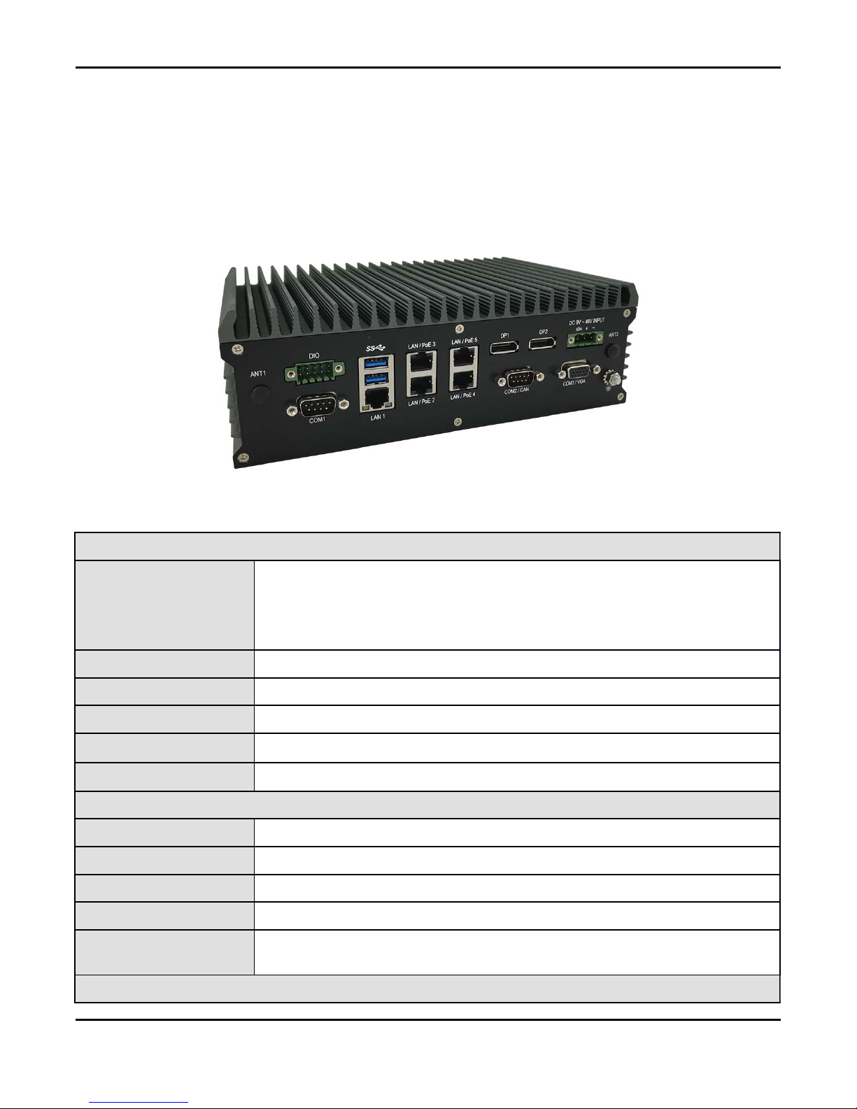
1.2 VBOX-3210 Illustration (MB, System).........................................................................................................9
1.3 Architecture...................................................................................................................................................13
1.4 Power Consumption.....................................................................................................................................13
2.0Internal Connector Specification.......................................................................................................................15
2.1 Battery Connector (BAT1)...........................................................................................................................15
2.2 COM Port Connector (COM1)....................................................................................................................16
2.3 COM Port Connector (COM2)....................................................................................................................17
2.4 COM Port Connector (COM3)....................................................................................................................18
2.5 COM Port Connector (COM4)....................................................................................................................19
2.6 MCU DOWN Connector..............................................................................................................................20
2.7 DIP Switch Connector..................................................................................................................................21
2.8 SATA Power Connector...............................................................................................................................22
2.9 SATA Connector...........................................................................................................................................23
2.10 USB Connector............................................................................................................................................24
2.11 DEBUG Connector.....................................................................................................................................25
2.12 SPI Connector.............................................................................................................................................26
2.13 UPS Connector............................................................................................................................................27
2.14 VGA Connector...........................................................................................................................................28
2.15 Mini PCI-E Connector (MINICARD1)....................................................................................................29
2.16 Mini PCI-E Connector (MINICARD2)....................................................................................................31
2.17 Mini PCI-E Connector (MINICARD3)....................................................................................................33
2.18 M.2 Connector.............................................................................................................................................35
2.19 CFAST Connector......................................................................................................................................37
3.0External Connector Specification......................................................................................................................39
3.1 Power Input Connector................................................................................................................................39
3.2 DP Connector (DP1).....................................................................................................................................40
3.3 DP Connector (DP2).....................................................................................................................................41
3.4 USB Connector..............................................................................................................................................42
User’s Manual

1.0 Introduction
3.5 LAN Connector (LAN1)...............................................................................................................................43
3.6 LAN Connector (LAN2)...............................................................................................................................44
3.7 LAN + USB 3.0 Connector...........................................................................................................................45
3.8 DIO Connector..............................................................................................................................................46
3.9 AUDIO Connector........................................................................................................................................47
4.0System Installation..............................................................................................................................................50
4.1 System Introduction.....................................................................................................................................50
4.2 Opening Chassis............................................................................................................................................51
4.3 Installing Memory.........................................................................................................................................53
4.4 Installing MINI PCIe Expansion Card (Minicard 1, 3G/LTE)................................................................55
4.5 Installing MINI PCIe Expansion Card (MiniCard 2)...............................................................................57
4.6 Installing MINI PCIe Expansion Card (MiniCard 3)...............................................................................59
4.7 Installing M.2 Module..................................................................................................................................61
4.8 Installing Internal Antenna Cable...............................................................................................................63
4.9 Installing SIM Card......................................................................................................................................67
4.10 Installing HDD............................................................................................................................................69
4.11 Installing CFast Card Module...................................................................................................................72
4.12 Installing POE Module...............................................................................................................................75
5.0BIOS....................................................................................................................................................................78
5.1 Enter The BIOS............................................................................................................................................78
5.2 Main...............................................................................................................................................................80
5.3 Advanced.......................................................................................................................................................81
5.4 Chipset...........................................................................................................................................................84
5.5 Boot................................................................................................................................................................86
6.0Packing List.........................................................................................................................................................89
6.1 Packing List...................................................................................................................................................89
User’s Manual

1.0 Introduction
1.0
INTRODUCTION
User’s Manual

1.0 Introduction
1.0 INTRODUCTION
1.1 ModelSpecification
System
CPU
AMDRX‐421BDQuadCore2.1GHzupto3.4GHz*
AMDRX‐216GDDualCore1.6GHzupto3.0GHz(OptionalGX‐224IJ,
GX‐215JJ)
*Configto15W
Memory 2xSO‐DIMMDDR4upto32GB(1xSO‐DIMMDDR4forGXseries)
Graphics AMDRadeon™graphics
ATA 2xSerialATAGEN3.0
LANChipset 2xInteli210‐AT;EthernetSwtich:1xMarvell88E6176
Watchdog 1~255LevelReset
PowerRequirement
PowerInput 9V‐48VDCPowerinput
PowerProtection AutomaticsRecoveryShortCircuitProtection
PowerManagement VehiclePowerIgnitionforVarietyVehicle
PowerOffControl PoweroffDelayTimeSettingbyBIOSandSoftware
Battery InternalBatteryKitfor10MinsOperating(Optional)
PatentNo.:M447854‐Build‐inBattery
Storage
User’s Manual Page 8

1.0 Introduction
Type 1x2.5"DriveBayforSATATypeHDD/SSD
1xCfastslot
Qualification
Certifications CE,FCCClassA,E13
I/O
SerialPort 2xRS232/422/485(optionadditional2xRS232)
USBPort 2xUSB3.0portsand2xUSB2.0Ports
LAN 5xRJ45PortsGbE(Optinalfor4xPOE802.3at/af*)
VideoPort 2xDP(Optionadditional1xVGAforRXseries)
GPIOPort 4Inand4Out
Audio Mic‐in/Line‐out(OptionalLinein)
ExpansionBus 3xMini‐cardslots
1xM.2A‐Ekey2230slot
Antenna Antenna4xSMA‐typeExternalAntennaConnectors
SIMCardSocket SIMCardSocket2xSIMCardSocketsSupportedOnboardwitheject
Environment
OperatingTemp. ‐40ºC~70ºC(w/SSD)
StorageTemp. ‐40ºC~85ºC
RelativeHumidity 5%RH–95%RH
Vibration(random) IEC60068‐2‐64,random,2.5G@5~500Hz,1hr/axiswithSSD
VibrationOperating MIL‐STD‐810G,Method514.6,ProcedureI,Category4
Shock Operating:MIL‐STD‐810G,Method516.6,ProcedureI,Trucksand
semi‐trailers=15G(11ms)withSSD
Mechanical
Construction AluminumAlloy
Mounting Wall‐mount,VESA‐mount,DinRailMountingKit
Weight 1405g(Barebone)
Dimensions 240(L)x161(W)x85(H)mm
1.2 FleetPC‐5‐BIllustration(MB,System)
MainBoard
User’s Manual Page 9

1.0 Introduction
FrontI/O
User’s Manual Page 10

1.0 Introduction
RearI/O
System
User’s Manual Page 11

1.0 Introduction
User’s Manual Page 12

1.0 Introduction
1.3 Architecture
EthernetSwitch
Marvell88E6176
MDIBUS RJ45
PORT2(PoE)
RJ45
PORT3(PoE)
MDIBUS
RJ45
PORT4(PoE)
RJ45
PORT5(PoE)
MDIBUS
MDIBUS
MiniPCI‐ESlot3
Fullfunction
FullSize
PCI‐EX1#3
MiniPCI‐ESlot2
Fullfunction
FullSize
PCI‐EX1#2
SATA3.0#0
SATAPORT1
CFastcard
SATAPORT0
7PINCON.
SATA3.0#1
UIMBUS
MiniPCI‐ESlot1
3G/LTE
FullSize
USB2.0#1
HDAudio
Realtek
ALC662
HDCodec
MICIN
FRONTOUT
USB2.0#3
USB2.0#2
TPM2.0
Type1DualChannel
Type3SingleChannel(CH‐B)
Type1SupportDP0,1,2
Type3SupportDP0,1
max:16GB
LINEOUT
MICIN
MDIBUS
RS232/422/485
HWMonitor
Volt agemonitor
TEMPSmonitor
SUPERI/O
FINTEK
F81866AD‐I
COMPORT1~4
2x5JST
LPCBUS
SIM1 SIM2
USB2.0#7
USB2.0HUB
DP0
CH7517A‐BF
VGA
JSTCON
VGA
Rseries‐SOC
MerlinFalcon(FP4)
RE421BAAY43KA(Type1)
CPU:4Core
Core:52.6A
NB:13.1A
GFX:43.6A
TDP:34W
RE216GAAY23KA(Type1)
CPU:4Core
Core:26.6A
NB:15.0A
GFX:34.7A
TDP:15W
GE224IAVY23AC(Type3)
CPU:2Core
Core:25.3A
NB:17.0A
GFX:NA
TDP:15W
GE215JAWY23AC(Type3)
CPU:2Core
Core:10.8A
NB:13.5A
GFX:NA
TDP:10W
GPIO4in/4out
2x5TerminalBlock
GPIO
RJ45
PORT1
USB2.0#0
GFX#7
M.2
A‐Ekey
USB2.0HUB#0~1
USB2.0
PORT1~4
USB2.0#4/#5
USB3.0
PORT1~2
SPIROM
64Mb
SPI
UIMBUS
AMD
PoEisoptional
LINEIN
LINEIN
DDR4BUS
SO‐DIMMDDR42400MHz
DUAL‐CH
DisplayPort1
DP1
DisplayPort2
DP2
968‐BALLBGA
29X37mm
PCI‐EX1#0
Intel
WGI210AT
GBE
Intel
WGI210AT
GBE
PCI‐EX1#1 MDIBUS
1.4 PowerConsumption
Chip Description
Intel Power consumption:
CPU Cores Core
Frequency L2 Cache TDP Tj
RX-421BD 4 2.1 GHz 2MB 12~35W 105°C
RX-216GD 2 1.6 GHz 1MB 12~15W 105°C
GX-224IJ 2 2.4 GHz 1MB 10~15W 105°C
GX-215JJ 2 1.5 GHz 1MB 6~10W 105°C
User’s Manual Page 13

2.0 Internal Connector Specification
2.0
INTERNALCONNECTOR
SPECIFICATION
User’s Manual

2.0 Internal Connector Specification
2.0 INTERNALCONNECTORSPECIFICATION
2.1 BatteryConnector(BAT1)
User’s Manual Page 15

2.0 Internal Connector Specification
2.2 COMPortConnector(COM1)
Connector size 2 X 5 = 10 Pin
Connector type JST-2.0mm-M-180
Connector location COM1
Connector pin
definition
Pin Signal Pin Signal
1 COM1_DCD 2 COM1_RXD
3 COM1_TXD 4 COM1_DTR
5 GND 6 COM1_DSR
7 COM1_RTS 8 COM1_CTS
9 COM1_RI 10 GND
DB9 pin definition
Pin Signal
RS232 RS422 RS485
1 COM1_DCD TXD- TXD-/RXD-
2 COM1_RXD TXD+ TXD+/RXD+
3 COM1_TXD RXD+ NC
4 COM1_DTR RXD- NC
5 GND GND GND
6 COM1_DSR NC NC
7 COM1_RTS NC NC
8 COM1_CTS NC NC
9 COM1_RI NC NC
User’s Manual Page 16

2.0 Internal Connector Specification
2.3 COMPortConnector(COM2)
Connector size 2 X 5 = 10 Pin
Connector type JST-2.0mm-M-180
Connector location COM2
Connector pin
definition
Pin Signal Pin Signal
1 COM2_DCD 2 COM2_RXD
3 COM2_TXD 4 COM2_DTR
5 GND 6 COM2_DSR
7 COM2_RTS 8 COM2_CTS
9 COM2_RI 10 GND
DB9 pin definition
Pin Signal
RS232 RS422 RS485
1 COM2_DCD TXD- TXD-/RXD-
2 COM2_RXD TXD+ TXD+/RXD+
3 COM2_TXD RXD+ NC
4 COM2_DTR RXD- NC
5 GND GND GND
6 COM2_DSR NC NC
7 COM2_RTS NC NC
User’s Manual Page 17

2.0 Internal Connector Specification
2.4 COMPortConnector(COM3)
Connector size 2 X 5 = 10 Pin
Connector type JST-2.0mm-M-180
Connector location COM3
Connector pin
definition
Pin Signal Pin Signal
1 COM3_DCD 2 COM3_RXD
3 COM3_TXD 4 COM3_DTR
5 GND 6 COM3_DSR
7 COM3_RTS 8 COM3_CTS
9 COM3_RI 10 GND
DB9 pin definition
Pin Signal
RS232 RS422 RS485
1 COM3_DCD TXD- TXD-/RXD-
2 COM3_RXD TXD+ TXD+/RXD+
3 COM3_TXD RXD+ NC
4 COM3_DTR RXD- NC
User’s Manual Page 18

2.0 Internal Connector Specification
2.5 COMPortConnector(COM4)
Connector size 2 X 5 = 10 Pin
Connector type JST-2.0mm-M-180
Connector location COM4
Connector pin
definition
Pin Signal Pin Signal
1 COM4_DCD 2 COM4_RXD
3 COM4_TXD 4 COM4_DTR
5 GND 6 COM4_DSR
7 COM4_RTS 8 COM4_CTS
9 COM4_RI 10 GND
DB9 pin definition
Pin Signal
RS232 RS422 RS485
1 COM4_DCD TXD- TXD-/RXD-
User’s Manual Page 19

2.0 Internal Connector Specification
2.6 MCUDOWNConnector
Connector size 1 X 4 = 4 Pin
Connector type JST-2.0mm-M-180
Connector location MCU_DOWN1
Connector pin
definition
Pin Signal
1 MCU_PROGRAM
2RXD
3 GND
4TXD
User’s Manual Page 20
Other manuals for FleetPC-5-B
1
Table of contents
Other Cartft Automobile Accessories manuals

Cartft
Cartft FleetPC-5-B User manual

Cartft
Cartft CALU-MC User manual

Cartft
Cartft FLEETPC-8-I7BPOE User manual

Cartft
Cartft FLEETPC-ARM-300 User manual

Cartft
Cartft FleetPC-2 User manual

Cartft
Cartft FleetPC-8-i7C User manual

Cartft
Cartft FLEETPC-4-F User manual

Cartft
Cartft FleetPC-4-B User manual

Cartft
Cartft FLEETPC-ARM-300 User manual

Cartft
Cartft FleetPC-2 User manual