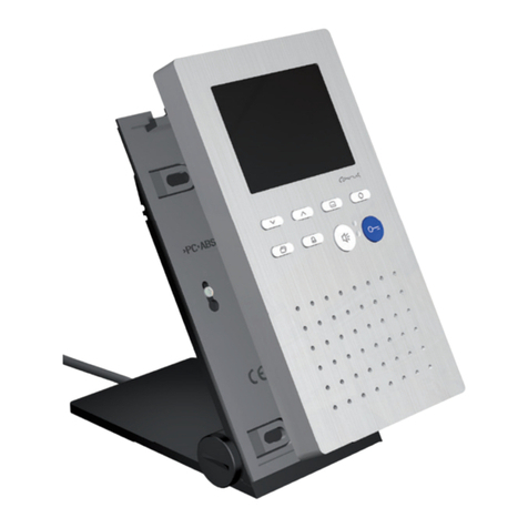
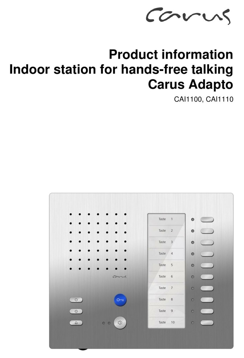
Carus Adapto CAI2100 User manual

Product information
Video indoor station for hands-free talking
Carus Adapto
CAI2100, CAI2110

2
Table ofcontents
Scope of delivery...............................................................................................................3
Safety instructions.............................................................................................................3
General safety regulations ...............................................................................................3
Installation –protective measures....................................................................................3
Technical data....................................................................................................................4
Device overview.................................................................................................................4
Indication and operating elements...................................................................................5
Intended use.......................................................................................................................6
Max. number CAI21x0 in 6-wire operation.......................................................................6
Short description...............................................................................................................6
Basicunit...........................................................................................................................6
Videounit..........................................................................................................................7
Mounting and installation .................................................................................................7
Installation CAI2100 (wall mounting)................................................................................7
Install the bottom shell..................................................................................................7
Connect the lines..........................................................................................................8
Terminating resistor CAI2100.......................................................................................8
Deinstall the device.......................................................................................................9
Installation CAI2110 (tabletop device)..............................................................................9
Put up the table rack...................................................................................................10
Cable assignment.......................................................................................................10
Terminating resistor CAI2110.....................................................................................10
Install the device.........................................................................................................10
Deinstall the device.....................................................................................................11
Wiring diagram...............................................................................................................11
Connection diagram.......................................................................................................12
Commissioning................................................................................................................12
Settings.............................................................................................................................12
Ring tone selection.........................................................................................................12
Factory settings..............................................................................................................13
Pre-adjusted times......................................................................................................13
AS-address dependent image activation....................................................................13
Configuration options .....................................................................................................14
Programming the basicmodule ......................................................................................14
Manual programming .....................................................................................................14
Programming the function key of the basic unit with Service Device TCSK-01..............18
General information on the conduit in TCS video systems .........................................18
6-wire operation..............................................................................................................18
Principle loop resistance.............................................................................................19
Measurement loop resistance.....................................................................................19
FAQ...................................................................................................................................20
Repair................................................................................................................................23
Cleaning............................................................................................................................23
Information on disposal ..................................................................................................23
Warranty...........................................................................................................................23
Service..............................................................................................................................24
3
Scope of delivery
1 x CAI21x0 (top shell, bottom shell or tabletop device)
2 x release bracket
4 x Phillips head screw
4 x dowel
assembly instruction
Product information
instruction manual
Safety instructions
General safety regulations
!
Attention! Assembly, installation, commissioning and repair of electronic devices must
be carried out by qualified electricians and in compliance with the current standards.
When working on main power connections of 230V AC, the general and regional installa-
tion and safety regulations must be met. i.e. DIN VDE 0100
TCS:BUS system installations must be in compliance with the general safety regulations
for telecommunication systems according to VDE 0800. Including:
separated cable routing of high and low voltage lines,
minimum distance of 10 cm in case of a common cable routing,
use of separators between high and low voltage lines within shared cable ducts,
use of standard telecommunication lines, e.g. J-Y (St) Y with 0.8 mm diameter,
already existing lines (modernisation) with deviating cross-sections can be used in
compliance with the loop resistance.
Installation –protective measures
!
Through suitable measures to protect against lightning, it has to be ensured that a
voltage of 32 V DC is not exceeded at each connection.

4
Technical data
supply voltage: +24 V ±8 % (power supply and control unit)
housing: aluminium anodised (colors as listed in price list)
dimensions CAI1100 H 163 mm x W 192 mm x D 16 mm
dimensions CAI1100: H 156 mm x W 192 mm x D 150 mm
weight: 936 g (CAI2100), 1473 g (CAI2110)
acceptable ambient temperature: 0 °C to 40 °C
input current: I(a) = 0.5 mA, I(P) = 4.7 mA
max. input current: I(Pmax) = 155 mA
3-wire installation necessary!
Device overview
indication ring tone
mute (red)
indication additional
functions (green)
door release
button
function key
light switch
button
call OFF-button
ring tone vol-
ume control
loudspeaker
basic module
microphone
speech
button
video mod-
ule
screen
4 navigation
buttons
left/right/
up/down
image
button
brightness
control
color
saturation
control

5
Indication and operating elements
Term
Function
speech button
call acceptance, activate speaking,
simplex communication
end communication
ring tone selection (door call front-door station 2 AS > AS-
border*)
door release but-
ton
door release (factory setting)
end communication
ring tone selection (door call front-door station 1 AS > AS-
border)
trigger light switch function**
function key of the
basic module
control function 8 (factory setting)
internal calling (to indoor station)
door release automatic
call diversion
ring tone selection internal call (call from the indoor sta-
tion)
light switch button
switching lights
ring tone selection floor call (call from the flat door)
call OFF-button
ring tone stopper
end communication
initiate the programming
indication ring
tone mute (red)
call OFF is activated (LED is ON) or
indication for busy speech channel (LED blinks)
indication addi-
tional functions
(green)
door call, incoming internal call, speaking activated
door release automatic or call diversion, when activated
alternatively door status indication
ring tone volume
control
ring tone volume can be adjusted continuously
image button
in the video mod-
ule
to switch in the image resp.
for switching between different cameras
4 navigation but-
tons
in the video mod-
ule
to swivel and incline a PTZ camera
(left, right, up, down)
brightness control
can be adjusted continuously
contrast / color
saturation control
can be adjusted continuously
* factory setting: AS-border = 0, limit value of the AS-address areas can be configured
with the configuration software configo™ or can be configured in the factory on request.
** when light switch function is activated in the front-door station

6
Intended use
The CAI21x0 are video indoor stations with color screen for hands-free talking. Manual-
ly controlled simplex communication can be activated.
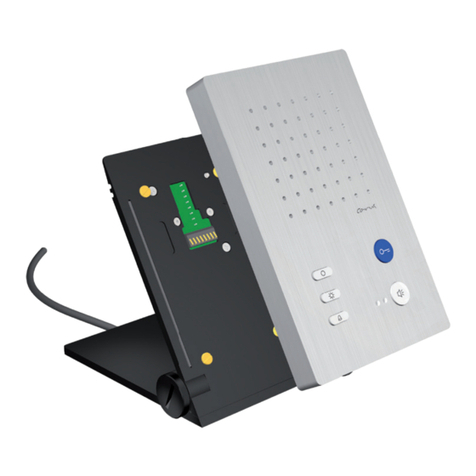
The CAI21x0 are suitable for surface-mount and can be used as tabletop device.
They can be used for the operation within TCS audio systems and combined audio /
video systems.
Max. number CAI21x0 in 6-wire operation
Small and medium-
sized systems
max. number CAI21x0
VBVS05
12
Larger systems
max. number CAI21x0
AS front-door station
VS power supply and control unit
IS indoor station
Note: The max. number of front-door stations which
can be connected is limited. Details are described in
the respective product information!
BVS20 + NGV1011
60
Short description
Basicunit
blue door release button with floor door release function (can be activated)
speech button: for call acceptance and changeover key speaking / listening
function key (ex works allocated with control function) with alternative allocation (can be
activated) internal call, door release automatic, call diversion
light switch button
ring tones can be adjusted by the resident, 13 ring tones can be selected
acoustic call distinction between 2 front-doors, flat door and internal call
ring tone volume can be adjusted manually
ring tone mute with optical indication
optical indication of door calls
optical display of a busy line in case of an established voice connection
automatic hands-free talking after internal call can be activated
one parallel call can be activated
sending sender serial number in case of internal calls can be de-/activated, source indi-
cation at CAI11x0 or CAI2xx0 possible (with configuration software configoTM)
unlimited communication time can be de-/activated (with configuration software con-
figoTM)

7
(limited by other indoor or front-door stations, to which a voice connection is estab-
lished)
audio privacy function and automatic call cut-off
Videounit
video surveillance: image button to activate the image resp. to switch between different
cameras
AS-dependent video image activation
4 navigation buttons (right, left, up, down)
brightness, color saturation / can be manually adjusted
integrated two-wire video receiver for direct connection to TCS video systems
Mounting and installation
Installation CAI2100 (wall mounting)
Attention!
The video indoor stations have to be (de-)installed only voltage-free!
Ensure not to over tighten the screws when installing the wall bottom shell on uneven sur-
faces. Otherwise the plate might be deformed. Further, the devices may not be locked into
position correctly on the bottom shell.
Install the bottom shell
For an optimal operation, a mounting height of 1.6 m is
recommended.
In order to plate the cables without any problems, the de-
vice must be installed on a flush-mounted socket.
Position the flush-mounted socket behind the cable
entry. Ensure that the connection terminal does not
contact the flush-mounted socket.
Do not use the bottom shell as drilling template!
Only use the bottom shell as aid for marking the holes.
Install the bottom shell directly to the wall and use the
enclosed screws to fix it.

8
Connect the lines
acceptable cross-section (diameter)
0.08 … 0.82 mm2(Ø 0.32 … 1.0 mm)
max. number of wires per terminal contact
each 2 x 0.8 mm, 3 x 0.6 mm
Further wires have to be connected via auxiliar terminals!
Use only connecting lines with the same diameter within one terminal contact.
Connect the lines according to the
labelling.
a
b
E
P
M
C
V1
V2
terminating resistor
Terminating resistor CAI2100
In delivery state the terminating resistor is inactive:
The jumper bridges the upper two contacts.
If the device is to be installed at the end of a cable chain, the
terminating resistor must be activated.
The jumper bridges the lower two contacts.
Install the device
Take the device into both hands and posi-
tion it on the bottom shell.
Position the device centrally on the bottom
shell and leave out a little space of 10 mm to
the bottom edge of the bottom shell.
Press the device flush to the bottom shell
(1). Slide it carefully and vertically down-
wards (2) until the lock pins of the bottom
shell lock into the holes in the rear panel of
the device.
Slide it downwards until stop.
To make sure that the device is locked cor-
rectly, slightly try to push it upwards. That
should not be possible.
Lock pins 4 x:
(1)
(2)

9
Deinstall the device
For deinstalling the device, the enclosed
release bracket is necessary.
Insert the release bracket into the opening
of the bottom shell behind the device (1).
Push the device upwards (2) and pull it out
towards you (3).
Installation CAI2110 (tabletop device)
Attention!
The video indoor stations have to be (de-)installed only voltage-free!
The table rack is pre-configured and has to be connected to a RJ45 socket. Therefore
please note the connection diagram under cable assignment.
1 bottom shell
2 lock pins
(4 x)
3 connecting cable
(2.5 m)
4knurled screws
5 grub screw
(hexagonal socket)
(1)
(3)
(2)
5
3
4
1
2

10
Put up the table rack
Turn the table rack into the desired position and
fix the position by tightening the knurled screws
by hand.
The cable is already pre-installed.
Cable assignment
Wires
Plug PIN no.
Connect to
connection terminal:
2
3
4
5
6
7
8
orange-green
green-white
blue
blue-white
green
brown-white
brown
a
b
E
P
M
V1
V2
Terminating resistor CAI2110
Observe when installing video tabletop devices:
The installation of the lines to the connection sockets must be realised star-shaped and
must NOT be looped through.
Noncompliance leads to a video image with limited quality.
Install the device
Take the device into both hands and position it
on the bottom shell.
Position the device centrally on the bottom shell
and leave out a little space of 10 mm to the bot-
tom edge of the bottom shell.
Press the device flush to the bottom shell (1).
Slide it carefully and vertically downwards (2)
until the lock pins of the bottom shell lock into
the holes in the rear panel of the device.
Slide it downwards until stop.
Tighten the grub screw with a suitable
screwdriver only by hand!
To make sure that the device is locked correctly,
slightly try to push it upwards. That should not
be possible.
max. 60°
(1)
(2)

12
Connection diagram
Commissioning
!
First install the system completely, than connect it to the mains voltage!
Install the devices of the system completely.
V1 and V2 must not be connected with the P-, a- or b-wire.
When connecting the video wires V1 (+) and V2 (−) the polarity must be observed.
Proof the a-, b- and P-wire against each other on short-circuit.
Switch on the main voltage.
Settings
Ring tone selection
For 4 different incoming calls (calls from 2 front-door stations, floor call, internal call) the
ring tones can be selected.
1
End voice communication: Press call OFF-button and
keep it pressed for around 8 s. A positive acknowledgement tone sounds.
The ring tone selection is activated.
By pressing the following buttons a ring tone can be selected. You can choose be-
tween 13 tones. 7 alpha tones, 6 gong tones.
2a
select door ring tone
of the front-door sta-
tion*
Press the door release button until the required ring tone
sounds. The ring tone selected last, will be stored.
2b
select door ring tone
of the second front-
door station
(if available)
Press the speech button until the required ring tone
sounds. The ring tone selected last, will be stored.
2c
select door ring tone
of the floor door
Press the light switch button until the required ring tone
sounds. The ring tone selected last, will be stored.

13
2d
select internal call
tone
Press the function key as often as the required ring tone
sounds. The ring tone selected last, will be stored.
3
Press call OFF button short.
In case that no button is pressed for around. 8 sec, the device ends the ring tone
selection automatically. An acknowledgement tone sounds, the ring tone selection
is deactivated.
* The first configuration of this door ring tone is adopted for the second front-door station.
Only after having select the ring tone for the second front-door station separately (2b), it always has to be selected in-
dependently.
Factory settings
Ex works the following settings are stored in the device:
serial number for parallel call
1000000
function key
control function 8
Pre-adjusted times
communication time
2 min
flashing period of the green LED, if the voice
channel is busy after the voice communication is
established
3 sec
3 x flashing
internal standby time, if the device is calling or is
called
around
30 s
floor door release time
around
30 s
AS-address dependent image activation
If there are also front-door stations without cameras in a system with CAI22x0 and video
front-door stations, the image is not activated when the CAI22x0 is called by an audio
front-door station.
To guarantee this function, the possible AS addresses are separated into two sections:
AS address
0 –31*
reserved for video front-door sta-
tions
the image is activated in case of a
door call (from max. 16 video front-
door stations)
AS address
as of 32*
free, for front-door stations with-
out camera
the image is not activated in case of a
door call
*) The video AS-border can be configured with the configurator configoTM.
Note:
The AS-addresses of the front-door stations have to be assigned via the Service Device.
For detailed information see section Service information in the TCS Installer 5 / 4 (Version 1) or TCS Installer 7 / 4
(Version 2).

14
Configuration options
Function
manually
TCSK-01
configoTM
as of version
1.7.x
fixed simplex communication
–
–
x
simplex communication to the front-door
station
–
–
x
ring tone volume
x
–
–
ring tones for 2 front-door calls, internal
calls and floor calls
x
–
x
call diversion
x
x
x
door release automatic
x
x
x
internal call via function key
x
x
x
control function 8 via function key
x
x
x
parallel allocation
–
x
x
floor door release function on / off
x
–
x
automatic hands-free talking after internal
call on / off
x
–
x
determine door call AS-border
–
–
x
block ring tone output
x
–
–
block ring tone selection
x
–
x
block programming
x
–
x
reload factory settings
x
–
x
determine video AS-border
–
–
x
Programming the basicmodule
Manual programming
Legend for programming
press button shortly
negative acknowledgement
(NoProg tone)
press the button until...
repeat
release the button
further
LEDs off
LEDs blinking
The programming is realised in four steps:
1
2
3
4
Initiate the programming
Pre-selection
End-selection
End the programming

15
1
Initiate the programming
Press the call OFF-button (8 sec), release
until an acknowledgement tone sounds shortly
Programming func-
tion
2
Pre-selection
3
End-selection
Press the button (8 sec) until an acknowl-
edgement tone sounds shortly and the green
LED blinks, release the button
shortly press the button,
an acknowledgement tone sounds
shortly and the green LED expires
door release automatic
call diversion
Note: Before program-
ming the call diversion,
the AS-address of the
front-door station is to
be fixed and blocked.
Execute at the required indoor station:
press speech button

16
Programming func-
tion
2
Pre-selection
3
End-selection
internal call
(at function key)
Execute at the required indoor station:
press speech button
control function 8
(on function key)
automatic hands-free
talking after internal call
switch on (when
switched off) or
switch off (when
switched on)
switch on floor door
release function (if
switched off) or
switch off (if switched
on)
parallel allocation
Execute at the required indoor station:
press speech button
delete
parallel allocation

17
Programming func-
tion
2
Pre-selection
3
End-selection
block ring tone selec-
tion
block extended pro-
gramming
deactivate program-
ming lock
Attention!
Switch on the pro-
gramming mode of
the system at the
BVS first.
Execute the steps 1
to 4.
Switch off the pro-
gramming mode of
the system.
Reload the factory set-
tings
press the door release button for 8
sec
4
End the programming
By shortly pressing the call OFF-button or automatically, if no button is pressed for 8 seconds.

18
Programming the function key of the basic unit with Service Device TCSK-01
door release automatic
call diversion
internal call 1
control function 8
parallel allocation
activate parallel call
switch off
NOTE: To deactivate parallel allocation means parallel allocation to
serial number 0.
ser. no. = the serial number of the indoor station that is to be configured new
TarSerNo. = the serial number of the indoor station, to which the call is to be diverted
IntSerNo. = the serial number of the indoor station, which is to be called internally
ParSNo. = the serial number of the indoor station, to which the new configured indoor station is allocated
General information on the conduit in TCS video systems
6-wire operation
6-wire operation is the standard operation mode. Video operation, where two separated
masses (b and M) are used.
The conduit is determined by structural conditions and is only limited by its length.
Please observe when selecting the length of the lines: the loop resistance a-b and M-P
must not exceed 8 Ω (table 1).
Loop resistance > 8 Ω: plan multiple wiring of the strands (double twisted lines).
Optional strand or star formed wiring
Do not use more than 20 indoor stations per strand. For systems with more video indoor
stations plan to use video distributors (FVY1200, FVY1400).
Up to 64 front-door stations (16 of them video front-door stations) and almost an unlim-
ited number of indoor stations can be connected within one system polarity-free (a/b;
polarity-free only in 6-wire operation). Thus, a suitable power supply and control unit is
to be used.
0

19
Table 1: loop resistances
Length of the line a-b/ M-P
in m
cable diameter
0.6 mm
0.8 mm
loop resitance in Ω
10
1.28
0.71
20
2.55
1.43
30
3.83
2.14
40
5.10
2.86
50
6.38
3.57
60
7.65
4.29
70
5.00
80
5.71
90
6.43
100
7.14
Principle loop resistance
Measurement loop resistance
None of the devices (AS, IS or FE) should ever be
located more than 8 Ohm away from the power
supply and control unit (VS).
Rule:
Switch off the 230 V / 50 Hz of the VS.
Install the a-b short-circuit at VS.
Other devices do not disturb the measurement,
they can stay connected.
Measure the resistance at a/b of the last IS or
AS.
8 Ohm:
max. 65 m distance AS-VS by 0.6 mm diameter
max. 115 m distance AS-VS by 0.8 mm diameter
AS front-door station
VS power supply and control unit
IS indoor station
FE extended function
a, b here
short-circuit

20
FAQ
Error pattern
Possible cause
Our suggested solution
The video image is black and
white.
The color saturation control of the
indoor station is set to a minimum.
Adjust the contrast or color satura-
tion control.
The transmission level of the vid-
eo BUS is too low.
At many components of the video
BUS (e.g. FVY) the transmission
level can be adjusted.
Please see the product information
of the active transmission compo-
nents.
The light saturation does not
reach the minimum value of 10
lux.
Thus, the camera switches over
to black and white.
The camera module of the front-
door station is very insensitive to
light. Ensure that there is sufficient
illumination or use an external cam-
era.
The colours of the video image
are too bright or the image in
general is too bright.
The color saturation is too high.
Reduce the color saturation.
The brightness too high.
Reduce the brightness.
The level of the video signal is too
high.
Turn down the level of the video bus
(e.g. rotary control on the board of
the camera). This only works, when
the terminating resistor is placed
correctly at the station or active
extended functions (e.g. FVY).
The terminating resistor at the
end of the strand is not plugged.
Plug the terminating resistor.
The colours of the video image
are without contrast.
The level of the video signal is not
high enough.
The connection line of a camera
was extended, although this is not
permitted.
The connection line between two
active video components was ex-
ceeded impermissible.
Loss of levels can be compensated
to a certain part by rotary controls at
active video components (see prod-
uct information of the components).
Check if the number of allowable
video indoor stations per strand was
not exceeded.
The terminating resistor at video
distributors or video switches with
looped-through signal are not
plugged correctly.
Remove the terminating resistors at
relevant components. Only the last
video component in a strand needs
a terminating resistor.
This manual suits for next models
1
Table of contents
Other Carus Intercom System manuals

Carus
Carus Adapto CAI2210 User manual

Carus
Carus IRIS CAE100 Series User manual

Carus
Carus IRIS User manual

Carus
Carus CAI 1100 User manual

Carus
Carus CAI 1010 User manual

Carus
Carus ARGOS CAE3 02-IP-015 Series User manual

Carus
Carus CAI 2010 User manual

Carus
Carus Adapto CAI1200 User manual

Carus
Carus CAI2300-015X User manual

Carus
Carus ARGOS User manual