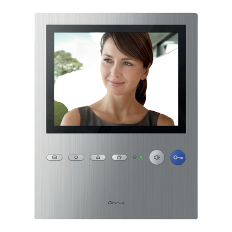
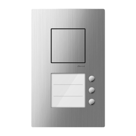
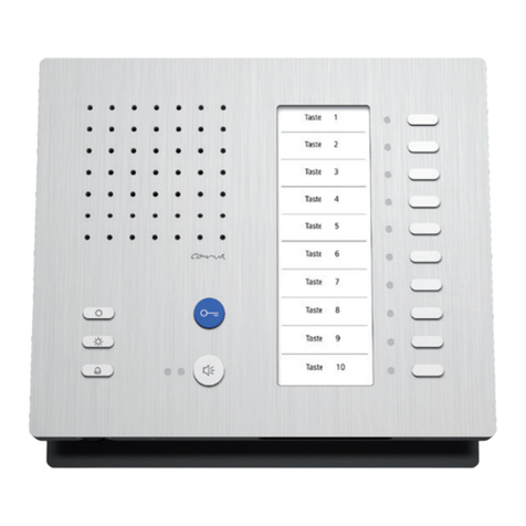
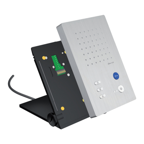
Carus ARGOS User manual

Product information
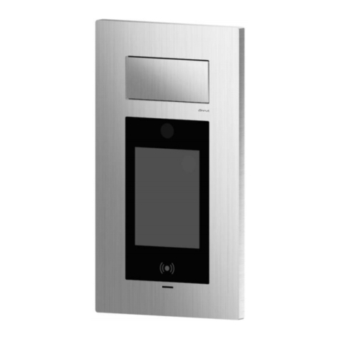
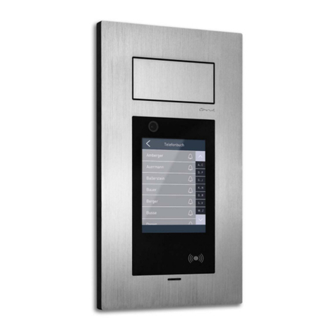
IP video front door station ARGOS
CAE3000-IP-015x
as of version 5.019

2

3
Table of contents
Scope of delivery............................................................................................................ 5
Introduction.................................................................................................................... 5
Notes on this product information .................................................................................................................................5
Used symbols and warning notices ..............................................................................................................................5
Further used symbols ...................................................................................................................................................5
Safety instructions......................................................................................................... 6
General safety regulations............................................................................................................................................6
Requirements to protect against lightning ....................................................................................................................6
Product description ....................................................................................................... 7
Intended use .................................................................................................................................................................7
Short description............................................................................................................ 7
RFID..............................................................................................................................................................................7
VIDEO...........................................................................................................................................................................7
AUDIO...........................................................................................................................................................................7
Operation / configuration ..............................................................................................................................................8
Event handler................................................................................................................................................................8
Interfaces ......................................................................................................................................................................8
Protocols .......................................................................................................................................................................9
Ambient conditions .......................................................................................................................................................9
Power supply ................................................................................................................................................................9
Housing.........................................................................................................................................................................9
Device overview........................................................................................................... 10
Technical data.............................................................................................................................................................11
Mounting and installation ............................................................................................ 11
Installation...................................................................................................................................................................11
Installation site..............................................................................................................................................................................11
Flush-mount..................................................................................................................................................................................12
Connecting the lines .....................................................................................................................................................................13
Put on the front plate ....................................................................................................................................................................14
Remove the front plate..................................................................................................................................................................14
Connecting the lines.................................................................................................... 15
Connecting lines...........................................................................................................................................................................15
Switch input, with 4 pins .............................................................................................................................................15
Relay output 1 and 2, each with 3 pins.......................................................................................................................15
Local power supply, with 2 pins ..................................................................................................................................16
Initial operation............................................................................................................ 17
Start screen.................................................................................................................................................................17
Configuration via OSD menu........................................................................................ 18
Overview configuration menu .....................................................................................................................................18
Camera .......................................................................................................................................................................18
Audio...........................................................................................................................................................................19
Volume..........................................................................................................................................................................................19
Microphone...................................................................................................................................................................................19
Display ........................................................................................................................................................................20
Automatic control..........................................................................................................................................................................20
Manual control..............................................................................................................................................................................20
Network.......................................................................................................................................................................21
IP address.....................................................................................................................................................................................21
Assigning the IP address manually...............................................................................................................................................21

4
Intercom function for visitor communication ............................................................. 22
Trigger a call.................................................................................................................................................................................22
Cancel a call.................................................................................................................................................................................22
Call accepted................................................................................................................................................................................22
End a call......................................................................................................................................................................................22
Control during a voice connection.................................................................................................................................................23
Set up the access control............................................................................................ 24
Put in employee data ..................................................................................................................................................24
Enrollment...................................................................................................................................................................24
Using the access control............................................................................................. 25
Access via RFID card .................................................................................................................................................25
Overview error messages RFID card............................................................................................................................................25
Access with access code............................................................................................................................................26
Overview error messages access code........................................................................................................................................26
Set up video surveillance ............................................................................................ 27
Extended configuration via web interface.................................................................. 28
Home screen...............................................................................................................................................................28
Login/Logout ...............................................................................................................................................................29
Admin password...........................................................................................................................................................................29
Special cards................................................................................................................................................................................30
System status .............................................................................................................................................................30
Menu Modifications.....................................................................................................................................................30
Telephone mode.........................................................................................................................................................31
Basic settings..............................................................................................................................................................31
User ............................................................................................................................................................................32
Set up access control with RFID UID............................................................................................................................................33
Set up access control with PIN code ............................................................................................................................................33
Access control with RFID UID and PIN code................................................................................................................................33
Network settings .........................................................................................................................................................34
SIP configuration ........................................................................................................................................................35
Audio/Video.................................................................................................................................................................36
Interface configuration ................................................................................................................................................37
Upload/Download .......................................................................................................................................................38
Cleaning........................................................................................................................ 39
Conformity.................................................................................................................... 39
Information on disposal ............................................................................................... 39
Warranty....................................................................................................................... 39
Service.......................................................................................................................... 40

5
Scope of delivery
1 x IP video front door station ARGOS
1 x wall-mount case for surface- and flush-mount
1 x installation kit with screws, dowels and sealing
1 x allen key with SW 2.0
3 x RFID cards: 1 x green, 1 x red and 1 x grey
1 x assembly instruction
1 x product information
Introduction
Notes on this product information
This product information refers exclusively to qualified electricians.
The product information contains important notes on intended use, installation and initial operation.
Please, keep the product information at a suitable place, where it is easily accessible for maintenance
and repair reasons.
You will find all product information in the download area at www.carus-concepts.com .
Used symbols and warning notices
Symbol Signal word Explanation
DANGER! The signal word describes an endangering with a high level of risk. Failure to ob-
serve this warning will result in death or very serious injury.
WARNING! The signal word describes an endangering with a medium level of risk. Failure to
observe this warning could result in death or very serious injury.
CAUTION! The signal word describes an endangering with a low level of risk. Failure to observe
this warning could result in a minor or moderate injury.
ATTENTION! The signal word indicates that damages on equipment, environment and property
can occur.
Further used symbols
Important note or important information
►Step
Cross reference for further information on this topic, see source
List, list entry 1 level
‐ List, list entry 2 level
a) Explanation

6
Safety instructions
General safety regulations
Assembly, installation, commissioning and repair of electronic devices must be carried out by
qualified electricians.
Observe the latest regulations and standards for system installations.
WARNING! Danger to life due to electric shock
When working on main power connections of 230 V, the safety regulations according to DIN
VDE 0100 must be observed.
When installing TCS:BUS systems the general safety regulations for telecommunication sys-
tems according to VDE 0800 must be observed. Inter alia:
separated cable routing of high and low voltage lines
minimum distance of 10 cm in case of a common cable routing
use of separators between high and low voltage lines within shared cable ducts
use of standard telecommunication lines, e.g. J-Y (St) Y with 0.8 mm diameter,
already existing lines (modernisation) with deviating cross-sections can be used in compli-
ance with the loop resistance
Observe the general requirements for network installations according to DIN EN 50173.
Requirements to protect against lightning
ATTENTION! Device damage due to over-voltage
By suitable lightning protection measures it has to be ensured that the electric voltage of 32 V
DC at each connection is not to be exceeded.

7
Product description
Intended use
The IP video front door station ARGOS is a terminal for access control that combines access control and
video door communication. Video door communication can be implemented into a network directly via
SIP phones.
The IP video front door station ARGOS is suitable for flush- and surface-mount in the outdoor area.
For applications, which differ from the intended use or goes beyond it, the manufacturer ac-
cepts no liability.
Short description
RFID
integrated RFID reader
MIFARE®
optionally adaptable for LEGIC® and iCLASS®
identification storage for up to 1000 persons
integrated code lock
identification query can be combined via RFID and code
VIDEO
integrated camera with 2 mega pixel CMOS colour sensor
wide angle objective with 100 degree opening angle
electronic PTZ control
video compression H.264, MJPEG, JPEG
video resolution VGA and CIF
frame rate with up to 30 images per second
anti-flickering
AUDIO
integrated microphone and loudspeaker
full duplex high power echo suppression
frequency range: 200 - 16,000 Hz
audio coding G.711 (A/µ-Law), G.729

8
Operation / configuration
capacitive colour touch screen with 5.7'' LCD (640 x 480 pixel)
brightness depends on the ambient light
configuration via LCD menus and web interface
customisable start screen
integrated data base, up to 1000 call destinations can be stored
Event handler
assigning events to actions
a maximum of 50 links can be configured
events:
– access control (RFID and/or PIN)
– tamper contact (contact, acceleration)
– SIP (INFO/DTMF, INVITE, BYE)
– trigger inputs
– RFID
– PIN
– TIMER
actions:
– video (PTZ, snapshot)
– relay
– SIP (INVITE, BYE, TALK)
– IP (HTTP GET, UDP Broadcast)
– LCD (Switch screen, Display ON/OFF)
Example 1:
An access event switches a relay. A video snapshot is taken and the message Access grant-
ed is displayed.
Example 2:
A relay is switched on in case of a SIP-DTMF signal and switched off after the timer period
has elapsed.
The configuration of the event handler is only approved for trained system integrators.
Interfaces
Ethernet, 10/100BaseT at RJ45 socket
2 x trigger input (door release button, feedback contact)
2 x relay changer (door release, light)
2-wire interface on spring-loaded terminal (with optional 2-wire kit)
integrated register server for peer-to-peer operation

9
Protocols
SIP RFC 3261, compatible to SIP (image) phones or Soft phones
TCP/UDP/IP, RTP, http, DNS, NTP, DHCP (Client), SNMP
Ambient conditions
temperature range: -20 °C to +60 °C
humidity up to 95%, non-condensing
ambient bright up to 50,000 lx
Power supply
Power over Ethernet (PoE) 802.3af and 802.3at
external mains adapter 12 V DC, 1 A (not polarity-free)
alternative power supply via mains adapter AC 20 V~ to 40 V~ or DC 24 V to 56 V (polarity-free)
Housing
housing made of solid aluminium
structured surface refined by hand
for flush- and surface-mount
colour: silver or black
tamper contact and acceleration sensor against vandalism

10
Device overview
1 housing made of aluminium 6 locking screw
2 loudspeaker 7 RFID reader
3 wall-mount case for surface- and flush-mount 8 microphone
4 pressure compensation element 9 display with touch screen
5 cable gland 10 camera

11
Technical data
supply voltage 12 V DC, 1 A (external mains adapter) or
2-wire Ethernet terminal 24 - 56 V DC (10 Watt) or
PoE IEEE 802.3af
power consumption,
in standby position
P = 6.6 W
maximum power consumption Pmax = 9.6 W
housing aluminium
dimensions (in mm) H 345 x W 192 x D 13 (49 mm incl. installation box)
weight 3 kg (incl. installation box)
acceptable ambient temperature -20 °C ... +60 °C
degree of protection IP65
Mounting and installation
Installation
Use the enclosed installation kit for installing the flush-mount box.
Installation site
For an optimal operation we recommend a mounting height of
1.57 m (centre of the device above ground, Fig. 1).
The ARGOS front door station is suitable for the
use in very bright surroundings.
Do not expose the camera to direct solar radiation.
Fig. 1: Mounting height

12
Flush-mount
►Make a wall cut out for the flush-mount box.
Use the flush-mount box as template for the wall cut
out.
Do not wall in or foam in the pressure compensa-
tion element.
Observe that there is a gap between the masonry
and the pressure compensation element.
►Mark the drilling holes with the help of the flush-mount box
(Fig. 2). For fixing the flush-mount box you can use the out-
er holes (1) or the inner holes, depending on the type of in-
stallation (2).
Ensure a vertical installation and the installation
position (3).
For the alignment use the integrated level.
The alignment of the device cannot be corrected
later.
►Put the enclosed dowels into the holes.
Use the enclosed sealing plugs (Fig. 3).
There are no warranty claims due to improper installa-
tion.
►Insert the sealing plug (4) into the flush-mount box.
►Close the cable gland that is not used with the enclosed
sealing plugs (5).
►Guide the connection cable through the cable gland and the
sealing plug.
►Fix the flush-mount box with 4 screws (6) to the wall (Fig.
4).
For marking the inner holes you can puncture the
sealing plugs with a small screwdriver.
The screws need to be screwed through the sealing
plugs. Thus, the device is sealed.
Fig. 2: Attachment holes
Fig. 3: Sealing plug
Fig. 4: Fixing the flush-mount box

13
Connecting the lines
For connecting external devices the ARGOS front door station
offers different interfaces. Those are located at the right side of
the circuit board (Fig. 5).
Pos. Designation
1 connection terminal (Fig. 6)
1A switching inputs
1B relay 2
1C relay 1
1D local power supply (12 V, 1 A)
2 2-wire connection (AC 20 V~ to 40 V~ or DC 24 V to 56
V)
3 Ethernet connection
For the installation you can remove the screw termi-
nals from the circuit board and pin them back on later.
►Connect the lines according to the labelling (Fig. 6).
Fig. 5: Ports
Fig. 6: Connection terminal

14
Put on the front plate
►Clip (1) the front plate (2) onto the guidance points (3) of
the flush-mount box (4).
►Push the front plate downwards.
►Secure the front plate with the locking screws (5).
Fig. 7: Putting on the front plate
Remove the front plate
►Screw out the locking screws (5).
►Push the front plate upwards.
►Remove the front plate.
►Remove the lines.
ATTENTION! Avoid damaging the front plate
Due to improper handling the front plate can get
damaged.
Place the front plate on a clean and dry surface.

15
Connecting the lines
Connecting lines
Acceptable cross section (diameter): 0.25 … 1.5 mm2(Ø 0.57 … 1.38 mm)
Maximum number of wires per terminal contact: 1
Connect further wires by using auxiliary terminals.
Use only connecting lines made of the same material and with the same diameter within one
terminal contact.
Switch input, with 4 pins
The device is equipped with 2 switching inputs to connect
bell buttons, door sensors or to connect with other devices.
Activate the switching inputs before using the web
interface. Set the activation status in deviating form if
necessary.
Additionally a connection with +12 V output voltages is lo-
cated on the screw terminal, which can be used for external
devices.
Fig. 8: Switch input with 4 pins
Relay output 1 and 2, each with 3 pins
There are 2 separated relay outputs, each is determined as changeover switch (
Fig. 9).
Technical data of the relay outputs:
nominally contact rating 2 A 30 V DC
0.5 A 125 V DC
maximum switching capacity (resistive
load)
60 W
62.5 VA
maximum switching voltage 220 V DV
125 V AC
maximum switching current 2 A
Fig. 9: Relay output 1 and 2, each with 3 pins

16
Local power supply, with 2 pins
ATTENTION! Damages on the device
Ensure the correct polarity when supplying the device via mains adapter (12 V, 1 A, DC volt-
age).
A wrong polarity may permanently damage the device.
For the power supply of external devices the +12 V
output at the switch can be used.
If a different voltage resp. a load > 2.5 W is need-
ed, an external voltage source is necessary.
The functionality of the relay can be adapted via the web
interface.
Switching the relay can be linked with different events,
e.g. with a successful identification.
Fig. 10: Relay output 1 and 2, each with 3 pins
If a power supply via Ethernet is not available, an external
mains adapter can be connected to supply the device (Fig.
11).
Suitable mains adapter are available as accessories.
The local power supply takes priority over the sup-
ply via Ethernet.
If a local power supply is connected to the device
while it is supplied via Ethernet, the device auto-
matically switches to the local power supply without
any interruption.
If the local supply is switched off and yet PoE is
available, the device is supplied via Ethernet after
an automatic reset.
Alternative power supply via 2-wire terminal, see page
13, ill. 5, pos. 2.
Fig. 11: Local power supply

17
Initial operation
WARNING! Danger to life due to electric shock
Observe the safety regulations according to DIN VDE 0100, when working on main power con-
nections of 230 V.
►Install the devices of the system voltage-free and completely.
►Switch on the mains voltage.
The device is not equipped with a separate ON/OFF switch.
After the mains power is connected, the device starts and displays the start screen.
Start screen
1 Telephone book 2 Input access code

18
Configuration via OSD menu
You need the red RFID card for the configuration via OSD
menu (Fig. 12).
Hold the red RFID card in front of the RFID reader. The con-
figuration menu is displayed (Fig. 13).
If there is no input within 30 sec, the configuration
mode is left automatically.
The time frame can be changed via the web inter-
face.
Fig. 12: Red RFID card
Overview configuration menu
In the configuration menu you can select the following menus:
camera
audio
display
IP address
tamper protection (no settings possible).
Fig. 13: Configuration menu
Camera
In the menu Camera the live image (1) of the camera is
displayed (Fig. 14).
In the menu Camera you can adjust and store 3 different
detecting areas (wide angle) of the camera.
►Select the menu Camera from the configuration menu.
►Tip a camera button (3).
►Slide the zoom controller (2) to the right to zoom into the
video image resp. to the left to zoom out of the video image.
►Tip the camera button (3) until an acknowledgement tone
sounds. The coverage is stored.
►Tip the Back button to get to the configuration menu.
In factory setting, the device is set at maximum
wide angle.
Select the image section that you have a clear view
on the person in front of the door.
Fig. 14: camera

19
Audio
Volume
The volume of the voice and tone output can be adapted to
the local conditions (Fig. 15).
►Select the menu Audio from the configuration menu.
►Slide the volume control of the Voice (1) resp. of the Tones
(2) to the right to increase the volume resp. to the left to re-
duce the volume.
To check the volume, a voice record is played.
►Tip the Back button to get to the configuration menu.
Fig. 15: Audio settings
Microphone
The microphone sensitivity offers 2 adjustment options:
‐ digital control (automatic control)
‐ analogue pre-amplification (Fig. 16).
We recommend switching on the automatic adapta-
tion, if the local acoustic conditions vary greatly.
►Select the menu Audio from the configuration menu.
►Slide the slide switch automatic control to ON (3).
The sensitivity of the microphone can be adjusted
independently, whether an automatic control was se-
lected or not.
►Slide the microphone control to the right to increase the
microphone sensitivity resp. to the left to reduce it (4).
In factory setting an average value is set.
►Tip the button Back to get to the configuration menu.
Fig. 16: Microphone settings

20
Display
A
utomatic control
The brightness of the display adapts automatically to the
ambient brightness.
The measured brightness is displayed under the slide
switch (1) (Fig. 17).
►Select the menu Display from the configuration menu.
►Slide the slide switch to the position Automatic (1). The
bright of the display is adapted automatically to the ambient
bright.
In factory setting the slide switch is in position Au-
tomatic.
The display is dimmed over night to minimise the
power consumption.
Manual control
►Slide the slide switch to the position Manual (1).
►Slide the bright control (2) to the right to increase the bright
resp. to the left to reduce it.
►Tip the Back button to get to the configuration menu.
Fig. 17: Display settings
Other manuals for ARGOS
1
Table of contents
Other Carus Intercom System manuals

Carus
Carus Adapto CAI2210 User manual

Carus
Carus CAI 1100 User manual

Carus
Carus IRIS CAE100 Series User manual

Carus
Carus CAI2300-015X User manual

Carus
Carus Adapto CAI1200 User manual

Carus
Carus IRIS User manual

Carus
Carus ARGOS User manual

Carus
Carus Adapto CAI1100 User manual

Carus
Carus Adapto CAI2100 User manual

Carus
Carus ARGOS CAE3 02-IP-015 Series User manual