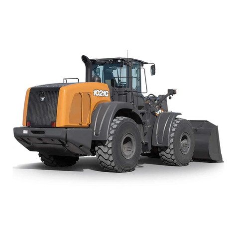
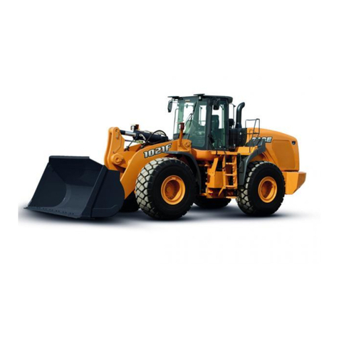
Case 921E User manual

SERVICE MANUAL
WHEEL LOADER
921E
TIER 3
English
Part Number 84299249
Printed in U.S.A. • Rac
© 2009 CNH America LLC. All Rights Reserved.
Case is a registered trademark of CNH America
84299249
(Replaces 87624950)
Revised December 2009
Issued February 2007
CNH AMERICA LLC
700 STATE STREET
RACINE, WI 53404 U.S.A.

84299250 Copyright © 2009 CNH America LLC.
All rights reserved.
Printed in U.S.A.
Issued December 2009
CNH America LLC.
700 State Street
Racine, WI 53404 U.S.A. (Replaces 5-5370)
921E Wheel Loader
Service Manual 84299249
(Replaces 87624950)
Table of Contents
Description Section No. Form No.
General Tab 1
Section Index - General 5-5380
Standard Torque Specifications 1001 8-71603
Fluids and Lubricants 1002 5-5390
Metric Conversion Chart 1003 7-52950
Engines Tab 2
Section Index - Engines 5-5400
Engine and Radiator Removal and Installation 2000 5-5410
Stall Tests 2002 5-5420
After Cooler 2003 5-5430
For Engine Repair See Your Cummins Dealer
Fuel System Tab 3
Section Index - Fuel System 5-5440
For Fuel System Repair, See Your Cummins Dealer
Electrical Tab 4
Section Index - Electrical 5-5450
Removal and Installation of Starter and Alternator 4001 5-5460
Electrical Specifications and Troubleshooting 4002 5-5470
Batteries 4003 6-42331
Instrument Cluster and Equipment Fault Codes 4005 5-5480
Steering Tab 5
Section Index - Steering 84299252
(Replaces 5-5490)
Removal and Installation of Steering Components 5001 5-5500
Steering Specifications, Pressure Checks, and Troubleshooting 5002 5-5510
Steering Control Valve 5003 5-5520
Steering Cylinders 5005 5-5530
Center Pivot 5006 5-5540
Auxiliary Steering Motor and Pump 5008 6-42430
Joystick Steering 5009 5-15970
Find manuals at https://best-manuals.com

84299250 Copyright © 2009 CNH America LLC.
All rights reserved.
Printed in U.S.A.
Issued December 2009
CNH America LLC.
700 State Street
Racine, WI 53404 U.S.A. (Replaces 5-5370)
Power Train Tab 6
Section Index - Power Train 5-5550
Removal and Installation of Power Train Components 6001 5-5560
Transmission Specifications, Pressure Checks, and Troubleshooting 6002 5-5570
Transmission 6003 5-5580
Front and Rear Axle 6004 5-5590
Drive Shafts, Center Bearing, and Universal Joints 6005 5-5600
Wheels and Tires 6006 5-5610
Transmission Control Valve 6007 6-42501
Brakes Tab 7
Section Index - Brakes 5-5620
Removal and Installation of Brake Components 7001 5-5630
Hydraulic Brake Troubleshooting 7002 5-5640
Parking Brake 7008 5-5650
Hydraulics Tab 8
Section Index - Hydraulics 5-5660
How to Read Symbols in a Hydraulic Schematic 8000 5-5670
Removal and Installation of Hydraulic Components 8001 5-5680
Hydraulic Specifications, Troubleshooting, and Pressure Checks 8002 5-5690
Cleaning the Hydraulic System 8003 5-5700
Hydraulic Pump 8004 5-5710
Loader Control Valve 8005 5-5720
Cylinders 8006 5-5730
Mounted Equipment Tab 9
Section Index - Mounted Equipment 5-5740
Air Conditioning Troubleshooting and System Checks 9002 5-5750
Air Conditioner System Service 9003 5-5760
Removal and Installation of Air Conditioning and Heater Components 9004 5-5770
Loader 9006 5-5780
The Rollover Protective Structure (ROPS) or Cab Structural Frame (CSF) 9007 5-5790
Cab Glass Installation 9010 6-42710
921E Wheel Loader
Service Manual 84299249
(Replaces 87624950)
Table of Contents
Description Section No. Form No.
Find manuals at https://best-manuals.com

84299250 Copyright © 2009 CNH America LLC.
All rights reserved.
Printed in U.S.A.
Issued December 2009
CNH America LLC.
700 State Street
Racine, WI 53404 U.S.A. (Replaces 5-5370)
NOTE: CNH America LLC. reserves the right to make improvements in design or
changes in specifications at any time without incurring any obligation to install
them on units previously sold.
Electrical Schematic Foldouts and Hydraulic Schematic Foldout In Rear Pocket 5-5800
921E Wheel Loader
Service Manual 84299249
(Replaces 87624950)
Table of Contents
Description Section No. Form No.
Find manuals at https://best-manuals.com

Copyright © 2007 CNH America LLC.
All rights reserved.
Printed in U.S.A.
Issued February, 2007
CASE, LLC.
700 State Street
Racine, WI 53404 U.S.A. Bur 5-5380
SECTION INDEX
GENERAL
Standard Torque Specifications. . . . . . . . . . . . . . . . . . . . . . . . . . . . . . . . . . . . . . . . . . . . . . . . . . . . . . . . . . . . . .1001
Fluids and Lubricants . . . . . . . . . . . . . . . . . . . . . . . . . . . . . . . . . . . . . . . . . . . . . . . . . . . . . . . . . . . . . . . . . . . . .1002
Metric Conversion Chart . . . . . . . . . . . . . . . . . . . . . . . . . . . . . . . . . . . . . . . . . . . . . . . . . . . . . . . . . . . . . . . . . . .1003
Section Title Section Number
Find manuals at https://best-manuals.com

1001-2
Bur 8-71603 Revised 7-05 Printed in U.S.A.
TABLE OF CONTENTS
TORQUE SPECIFICATIONS - DECIMAL HARDWARE . . . . . . . . . . . . . . . . . . . . . . . . . . . . . . . . . . . . . . . . . . . . 3
TORQUE SPECIFICATIONS - METRIC HARDWARE . . . . . . . . . . . . . . . . . . . . . . . . . . . . . . . . . . . . . . . . . . . . . 4
TORQUE SPECIFICATIONS - STEEL HYDRAULIC FITTINGS . . . . . . . . . . . . . . . . . . . . . . . . . . . . . . . . . . . . . 5
TORQUE SPECIFICATIONS - STEEL HYDRAULIC FITTINGS . . . . . . . . . . . . . . . . . . . . . . . . . . . . . . . . . . . . . 6
Find manuals at https://best-manuals.com

1001-3
Bur 8-71603 Revised 7-05 Printed in U.S.A.
TORQUE SPECIFICATIONS - DECIMAL HARDWARE
Use the torques in this chart when special torques
are not given. These torques apply to fasteners with
both UNC and UNF threads as received from
suppliers dry, or when lubricated with engine oil. Not
applicable if special graphities, Molydisulfide
greases, or other extreme pressure lubricants are
used.
Grade 5 Bolts, Nuts, and Studs
Size
Pound-
Inches
Newton
metres
1/4 inch 108 to 132 12 to 15
5/16 inch 204 to 252 23 to 28
3/8 inch 420 to 504 48 to 57
Size
Pound-
Feet
Newton
metres
7/16 inch 54 to 64 73 to 87
1/2 inch 80 to 96 109 to 130
9/16 inch 110 to 132 149 to 179
5/8 inch 150 to 180 203 to 244
3/4 inch 270 to 324 366 to 439
7/8 inch 400 to 480 542 to 651
1.0 inch 580 to 696 787 to 944
1-1/8 inch 800 to 880 1085 to 1193
1-1/4 inch 1120 to 1240 1519 to 1681
1-3/8 inch 1460 to 1680 1980 to 2278
1-1/2 inch 1940 to 2200 2631 to 2983
Grade 8 Bolts, Nuts, and Studs
Size
Pound-
Inches
Newton
metres
1/4 inch 144 to 180 16 to 20
5/16 inch 288 to 348 33 to 39
3/8 inch 540 to 648 61 to 73
Size
Pound-
Feet
Newton
metres
7/16 inch 70 to 84 95 to 114
1/2 inch 110 to 132 149 to 179
9/16 inch 160 to 192 217 to 260
5/8 inch 220 to 264 298 to 358
3/4 inch 380 to 456 515 to 618
7/8 inch 600 to 720 814 to 976
1.0 inch 900 to 1080 1220 to 1465
1-1/8 inch 1280 to 1440 1736 to 1953
1-1/4 inch 1820 to 2000 2468 to 2712
1-3/8 inch 2380 to 2720 3227 to 3688
1-1/2 inch 3160 to 3560 4285 to 4827
NOTE: Use thick nuts with Grade 8 bolts.
Find manuals at https://best-manuals.com
1001-4
Bur 8-71603 Revised 7-05 Printed in U.S.A.
TORQUE SPECIFICATIONS - METRIC HARDWARE
Use the following torques when specifications are not
given.
These values apply to fasteners with coarse threads
as received from supplier, plated or unplated, or
when lubricated with engine oil. These values do not
apply if graphite or Molydisulfide grease or oil is
used.
Grade 12.9 Bolts, Nuts, and Studs
Usually the torque values specified for grade 10.9
fasteners can be used satisfactorily on grade 12.9
fasteners.
Grade 8.8 Bolts, Nuts, and Studs
Size
Pound-
Inches
Newton
metres
M4 24 to 36 3 to 4
M5 60 to 72 7 to 8
M6 96 to 108 11 to 12
M8 228 to 276 26 to 31
M10 456 to 540 52 to 61
Size
Pound-
Feet
Newton
metres
M12 66 to 79 90 to 107
M14 106 to 127 144 to 172
M16 160 to 200 217 to 271
M20 320 to 380 434 to 515
M24 500 to 600 675 to 815
M30 920 to 1100 1250 to 1500
M36 1600 to 1950 2175 to 2600
8.8
Grade 10.9 Bolts, Nuts, and Studs
Size
Pound-
Inches
Newton
metres
M4 36 to 48 4 to 5
M5 84 to 96 9 to 11
M6 132 to 156 15 to 18
M8 324 to 384 37 to 43
Size
Pound-
Feet
Newton
metres
M10 54 to 64 73 to 87
M12 93 to 112 125 to 150
M14 149 to 179 200 to 245
M16 230 to 280 310 to 380
M20 450 to 540 610 to 730
M24 780 to 940 1050 to 1275
M30 1470 to 1770 2000 to 2400
M36 2580 to 3090 3500 to 4200
10.9
12.9
Find manuals at https://best-manuals.com

1001-5
Bur 8-71603 Revised 7-05 Printed in U.S.A.
TORQUE SPECIFICATIONS - STEEL HYDRAULIC FITTINGS
37 Degree Flare Fitting
Tube OD
Hose ID
Thread
Size
Pound-
Inches
Newton
metres
1/4 inch
6.4 mm
7/16-20 72 to 144 8 to 16
5/16 inch
7.9 mm
1/2-20 96 to 192 11 to 22
3/8 inch
9.5 mm
9/16-18 120 to 300 14 to 34
1/2 inch
12.7 mm
3/4-16 180 to 504 20 to 57
5/8 inch
15.9 mm
7/8-14 300 to 696 34 to 79
Tube OD
Hose ID
Thread
Size
Pound-
Feet
Newton
metres
3/4 inch
19.0 mm
1-1/16-12 40 to 80 54 to 108
7/8 inch
22.2 mm
1-3/16-12 60 to 100 81 to 135
1.0 inch
25.4 mm
1-5/16-12 75 to 117 102 to 158
1-1/4 inch
31.8 mm
1-5/8-12 125 to 165 169 to 223
1-1/2 inch
38.1 mm
1-7/8-12 210 to 250 285 to 338
Split Flange Mounting Bolts
Size
Pound-
Inches
Newton
metres
5/16-18 180 to 240 20 to 27
3/8-16 240 to 300 27 to 34
7/16-14 420 to 540 47 to 61
Size
Pound-
Feet
Newton
metres
1/2-13 55 to 65 74 to 88
5/8-11 140 to 150 190 to 203
Straight Threads with O-ring
Tube OD
Hose ID
Thread
Size
Pound-
Inches
Newton
metres
1/4 inch
6.4 mm
7/16-20 144 to 228 16 to 26
5/16 inch
7.9 mm
1/2-20 192 to 300 22 to 34
3/8 inch
9.5 mm
9/16-18 300 to 480 34 to 54
1/2 inch
12.7 mm
3/4-16 540 to 804 57 to 91
Tube OD
Hose ID
Thread
Size
Pound-
Feet
Newton
metres
5/8 inch
15.9 mm
7/8-14 58 to 92 79 to 124
3/4 inch
19.0 mm
1-1/16-12 80 to 128 108 to 174
7/8 inch
22.2 mm
1-3/16-12 100 to 160 136 to 216
1.0 inch
25.4 mm
1-5/16-12 117 to 187 159 to 253
1-1/4 inch
31.8 mm
1-5/8-12 165 to 264 224 to 357
1-1/2 inch
38.1 mm
1-7/8-12 250 to 400 339 to 542
Find manuals at https://best-manuals.com

1001-6
Bur 8-71603 Revised 7-05 Printed in U.S.A.
TORQUE SPECIFICATIONS - STEEL HYDRAULIC FITTINGS
O-ring Face Seal End
O-ring Boss End
Fitting or Lock Nut
Nom.
SAE
Dash
Size Tube OD
Thread
Size
Pound-
Inches
Newton
metres
Thread
Size
Pound-
Inches
Newton
metres
-4 1/4 inch
6.4 mm
9/16-18 120 to 144 14 to 16 7/16-20 204 to 240 23 to 27
-6 3/8 inch
9.5 mm
11/16-16 216 to 240 24 to 27 9/16-18 300 to 360 34 to 41
-8 1/2 inch
12.7 mm
13/16-16 384 to 480 43 to 54 3/4-16 540 to 600 61 to 68
Thread
Size
Pound-
Feet
Newton
metres
-10 5/8 inch
15.9 mm
1-14 552 to 672 62 to 76 7/8-14 60 to 65 81 to 88
Nom.
SAE
Dash
Size Tube OD
Thread
Size
Pound-
Feet
Newton
metres
1-1/16-12 85 to 90 115 to 122
1-3/16-12 95 to 100 129 to 136
-12 3/4 inch
19.0 mm
1-3/16-12 65 to 80 90 to 110 1-5/16-12 115 to 125 156 to 169
-14 7/8 inch
22.2 mm
1-3/16-12 65 to 80 90 to 110 1-5/8-12 150 to 160 203 to 217
-16 1.0 inch
25.4 mm
1-7/16-12 92 to 105 125 to 140 1-7/8-12 190 to 200 258 to 271
-20 1-1/4 inch
31.8 mm
1-11/16-12 125 to 140 170 to 190
-24 1-1/2 inch
38.1 mm
2-12 150 to 180 200 to 254

Section
1002
1002
Copyright © 2007 CNH Ameica LLC.
All rights reserved.
Printed in U.S.A.
Issued February, 2007
CNH America LLC.
700 State Street
Racine, WI 53404 U.S.A. Bur 5-5390
FLUIDS AND LUBRICANTS

1002-2
Bur 5-5390 Issued 2-07 Printed in U.S.A.
TABLE OF CONTENTS
CAPACITIES AND LUBRICANTS . . . . . . . . . . . . . . . . . . . . . . . . . . . . . . . . . . . . . . . . . . . . . . . . . . . . . . . . . . . . . 3
ENGINE OIL RECOMMENDATIONS . . . . . . . . . . . . . . . . . . . . . . . . . . . . . . . . . . . . . . . . . . . . . . . . . . . . . . . . . . 4
DIESEL FUEL SYSTEM . . . . . . . . . . . . . . . . . . . . . . . . . . . . . . . . . . . . . . . . . . . . . . . . . . . . . . . . . . . . . . . . . . . . 5
Fuel Storage . . . . . . . . . . . . . . . . . . . . . . . . . . . . . . . . . . . . . . . . . . . . . . . . . . . . . . . . . . . . . . . . . . . . . . . . . . . 5
Specifications for Acceptable No. 2 Diesel Fuel . . . . . . . . . . . . . . . . . . . . . . . . . . . . . . . . . . . . . . . . . . . . . . . . 5
Biodiesel Information . . . . . . . . . . . . . . . . . . . . . . . . . . . . . . . . . . . . . . . . . . . . . . . . . . . . . . . . . . . . . . . . . . . . . 5
MAINTENANCE SCHEDULE . . . . . . . . . . . . . . . . . . . . . . . . . . . . . . . . . . . . . . . . . . . . . . . . . . . . . . . . . . . . . . . . 6
Model 921E . . . . . . . . . . . . . . . . . . . . . . . . . . . . . . . . . . . . . . . . . . . . . . . . . . . . . . . . . . . . . . . . . . . . . . . . . . . . 6

1002-3
Bur 5-5390 Issued 2-07 Printed in U.S.A.
CAPACITIES AND LUBRICANTS
Engine Oil
Capacity with Filter Change ......................................................................................... 30.0 liters (32 U.S. quarts)
Type of oil .............. Case AKCELA No. 1 (SAE 15W-40) engine oil - see engine oil recommendations on page 4
Engine Cooling System
Capacity...................................................................................................................56.8 liters (15.0 U.S. Gallons)
Type of Coolant ............................................................................................50% water and 50% Ethylene Glycol
Fuel Tank
Capacity ................................................................................................................. 393.7 liters (104 U.S. Gallons)
Type of Fuel............................................................................................. See Diesel fuel specifications on page 5
Hydraulic System
Hydraulic Reservoir Refill Capacity with Filter Change ............................................. 130 liters (34.0 U.S. Gallons)
Total System Capacity............................................................................................ 242.0 liters (64.0 U.S. Gallons)
Type of Oil ..............................................................................................................Case AKCELA Hy-Tran Ultra®
Transmission
Refill Capacity with Filter Change ..............................................................................28.4 liters (7.5 U.S. Gallons)
Total System Capacity..............................................................................................44.5 liters (11.8 U.S. Gallons)
Type of Oil .............................................................................................................. Case AKCELA No. 1 (15W-40)
Axles
Capacity
Front with out axle coolers ................................................................................... 51.0 liters (13.5 U.S. Gallons)
Rear with out axle coolers....................................................................................51.0 liters (13.5 U.S. Gallons)
Front with axle coolers .........................................................................................55.0 liters (14.5 U.S. Gallons)
Rear with axle coolers..........................................................................................55.0 liters (14.5 U.S. Gallons)
Type of Lubricant.......................................................................... Case AKCELA (SAE 80W-140) Transaxle Fluid
Brake System
Type of Fluid (Same as Hydraulic System) ...........................................................Case AKCELA Hy-Tran Ultra®
NOTE: DO NOT use an alternate oil in the axles. The brake components in the axles could be damaged as a result
of using an alternate oil.

1002-4
Bur 5-5390 Issued 2-07 Printed in U.S.A.
ENGINE OIL RECOMMENDATIONS
Case AKCELA No. 1 Engine oil is recommended
for use in your Case engine. Case AKCELA No. 1
Engine Oil will lubricate your engine correctly
under all operating conditions.
If Case AKCELA No. 1 Multi-Viscosity Oil is not
available, use only oil meeting API engine oil service
category CH-4 (preferred) or CG-4.
See the chart below for
recommended viscosity at
ambient air temperature
ranges.
NOTE: Do not put performance
additives or other oil additive
products in the engine
crankcase. The oil change
intervals given in this manual
are according to tests with Case
AKCELA lubricants.
BD03A102
BC02N250
RH99K130

1002-5
Bur 5-5390 Issued 2-07 Printed in U.S.A.
DIESEL FUEL SYSTEM
Use No. 2 diesel fuel in the engine of this machine.
The use of other fuels can cause the loss of engine
power and high fuel consumption.
In very cold temperatures, a mixture of No. 1 and No.
2 diesel fuels is temporarily permitted. See the
following Note.
NOTE: See your fuel dealer for winter fuel
requirements in your area. If the temperature of the
fuel lowers below the cloud point (wax appearance
point), wax crystals in the fuel will restrict the fuel
filter and cause the engine to lose power or not start.
The diesel fuel used in this machine must meet the
specifications as shown below in, “Specifications for
Acceptable No. 2 Diesel Fuel”, or “Specification
D975-81” of the American Society for Testing and
Materials.
Fuel Storage
If you keep fuel in storage for a period of time, you
can get foreign material or water in the fuel storage
tank. Many engine problems are caused by water in
the fuel.
Keep the fuel storage tank outside and keep the fuel
as cool as possible. Remove water from the storage
container at regular periods of time.
Fill the fuel tank at the end of the daily operating
period to prevent condensation in the fuel tank.
Specifications for Acceptable No. 2 Diesel Fuel
API gravity, minimum ............................................................................................................................................. 34
Flash point, minimum ............................................................................................................................60°C (140°F)
Cloud point (wax appearance point), maximum ...........................................................-20°C (-5°F) See Note above
Pour point, maximum ..................................................................................................-26°C (-15°F) See Note above
Distillation temperature, 90% point ................................................................................282 to 338°C (540 to 640°F)
Viscosity, at 38°C (100°F)
Centistokes ......................................................................................................................................... 2.0 to 4.3
Cetane number, minimum .......................................................................... 43 (45 to 55 for winter or high altitudes)
Water and sediment, by volume, maximum ..................................................................................................... 0.05%
Biodiesel Information
*- Must meet the D 975 specification for diesel fuels.
**-Must meet the ASTM D6751-03A specification.
NOTE: B20 Biodiesel is not approved for common
rail diesel engines at this time.
General Fuel Final Boiling Cetane Sulfur Content
Classification Point (Max) (Min) (Max)
B5 * (5% Biodiesel) < 360° C (680° F) 47 0.05%
B20 ** (20% Biodiesel) < 360° C (680° F) 47 0.05%

1002-6
Bur 5-5390 Issued 2-07 Printed in U.S.A.
MAINTENANCE SCHEDULE
Model 921E
AS REQUIRED
SERVICE THE AIR CLEANER IF THE AIR CLEANER WARNING LAMP ILLUMINATES ........................................ SEE OPERATORS MANUAL
REPLACE THE TRANSMISSION FILTER
IF THE TRANSMISSION FILTER RESTRICTION WARNING LAMP ILLUMINATES.......................................................... USE CASE FILTER
CHECK THE RADIATOR COOLANT LEVEL IF THE WARNING LAMP ILLUMINATES ........................................... SEE OPERATORS MANUAL
REPLACE THE HYDRAULIC FILTER IF THE HYDRAULIC FILTER WARNING LAMP ILLUMINATES................................... USE CASE FILTER
EVERY 10 HOURS OF OPERATION OR EACH DAY - WHICHEVER OCCURS FIRST
CHECK THE ENGINE OIL LEVEL............................................................................................................................. SEE OPERATORS MANUAL
DRAIN THE FUEL/WATER SEPARATOR .................................................................................................................. SEE OPERATORS MANUAL
CHECK THE ALTERNATOR, AC BELT...................................................................................................................... SEE OPERATORS MANUAL
EVERY 50 HOURS OF OPERATION
CHECK THE TRANSMISSION OIL LEVEL (ENGINE RUNNING AND OIL WARM)................................................. SEE OPERATORS MANUAL
CHECK THE HYDRAULIC RESERVOIR FLUID LEVEL ........................................................................................... SEE OPERATORS MANUAL
CHECK THE ENGINE COOLANT SURGE TANK ..................................................................................................... SEE OPERATORS MANUAL
LUBRICATE THE BELLCRANK AND BUCKET PIVOTS (6 FITTINGS) Z-BAR ................................ CASE AKCELA MOLYDISULFIDE GREASE
LUBRICATE REAR AXLE TRUNNION PINS (2 FITTINGS) .............................................................. CASE AKCELA MOLYDISULFIDE GREASE
EVERY 100 HOURS OF OPERATION
LUBRICATE THE STEERING CYLINDER PIVOTS - ROD AND CLOSED END (4 FITTINGS) ........ CASE AKCELA MOLYDISULFIDE GREASE
LUBRICATE THE LOADER LIFT ARM AND CYLINDER PIVOTS (7 FITTINGS) Z-BAR .................. CASE AKCELA MOLYDISULFIDE GREASE
LUBRICATE THE FRONT DRIVE SHAFT SUPPORT BEARING...................................................... CASE AKCELA MOLYDISULFIDE GREASE
EVERY 250 HOURS OF OPERATION
CHANGE COOLANT FILTER..................................................................................................................................... SEE OPERATORS MANUAL
CHECK THE TIRE CONDITION AND AIR PRESSURE............................................................................................ SEE OPERATORS MANUAL
CLEAN THE CAB AIR FILTERS ................................................................................................................................ SEE OPERATORS MANUAL
REPLACE FUEL FILTER ........................................................................................................................................... SEE OPERATORS MANUAL
EVERY 500 HOURS OF OPERATION
CHANGE THE ENGINE OIL AND REPLACE THE ENGINE OIL FILTER ................................................................. SEE OPERATORS MANUAL
CHECK THE BATTERY FLUID LEVEL ...................................................................................................................... SEE OPERATORS MANUAL
DRAIN WATER AND SEDIMENT FROM THE FUEL TANK ...................................................................................... SEE OPERATORS MANUAL
CHECK THE AXLE OIL LEVEL FRONT AND REAR ................................................................................................ SEE OPERATORS MANUAL
CHECK ROPS AND SEAT BELT MOUNTING BOLTS .............................................................................................. SEE OPERATORS MANUAL
EVERY 1000 HOURS OF OPERATION
REPLACE THE HYDRAULIC FILTERS (2) ............................................................................................................................... USE CASE FILTER
REPLACE THE TRANSMISSION OIL FILTERS (2) ................................................................................................................. USE CASE FILTER
CHANGE THE TRANSMISSION OIL......................................................................................................................... SEE OPERATORS MANUAL
CHANGE CAB AIR FILTERS ..................................................................................................................................... SEE OPERATORS MANUAL
LUBRICATE THE UPPER AND LOWER CHASSIS PIVOTS (2 FITTINGS)...................................... CASE AKCELA MOLYDISULFIDE GREASE
CHANGE THE FRONT/REAR AXLE OIL (AND FILTERS IF EQUIPPED) ................................................................ SEE OPERATORS MANUAL
EVERY 1500 HOURS OF OPERATION
ADJUST THE ENGINE VALVE CLEARANCES ....................................................................................................SEE YOUR CUMMINS DEALER
EVERY 2000 HOURS OF OPERATION OR EACH YEAR - WHICHEVER OCCURS FIRST
CHANGE THE HYDRAULIC OIL ............................................................................................................................... SEE OPERATORS MANUAL
DRAIN, FLUSH AND REFILL THE ENGINE COOLING SYSTEM .................................................................. ETHYLENE GLYCOL AND WATER
REPLACE THE AIR CLEANER ELEMENTS ..........................................................................................................................USE CASE FILTERS
If you operate the machine in severe conditions,
lubricate and service the machine more frequently. It
is recommended that you see your Case dealer for
information on the Systemgard Lubrication Analysis
System.
See your Operators manual for maintenance of
safety related items and for detailed information of
the service items on this chart. Operators and
service manuals are available for this machine from
your Case dealer.

Section
1003
1003
Copyright © 2003 CNH Ameica LLC.
All rights reserved.
Printed in U.S.A.
Issued April, 2003
CNH America LLC.
700 State Street
Racine, WI 53404 U.S.A. Bur 7-52590
METRIC CONVERSION CHART

1003-2
Bur 7-52590 Issued 4-03 Printed in U.S.A.
TABLE OF CONTENTS
CONVERSION FACTORS . . . . . . . . . . . . . . . . . . . . . . . . . . . . . . . . . . . . . . . . . . . . . . . . . . . . . . . . . . . . . . . . . . 3
Metric to U.S. . . . . . . . . . . . . . . . . . . . . . . . . . . . . . . . . . . . . . . . . . . . . . . . . . . . . . . . . . . . . . . . . . . . . . . . . . . 3
U.S. to Metric . . . . . . . . . . . . . . . . . . . . . . . . . . . . . . . . . . . . . . . . . . . . . . . . . . . . . . . . . . . . . . . . . . . . . . . . . . 4

1003-3
Bur 7-52590 Issued 4-03 Printed in U.S.A.
CONVERSION FACTORS
Metric to U.S.
MULTIPLY BY TO OBTAIN
Area: sq. meter
hectare
10.763 91
2.471 05
square foot
acre
Force: newton
newton
3.596 942
0.224 809
ounce force
pound force
Length: millimeter
meter
kilometer
0.039 370
3.280 840
0.621 371
inch
foot
mile
Mass: kilogram 2.204 622 pound
Mass/Area: kilogram/hectare 0.000 466 ton/acre
Mass/Energy: gr/kW/hr. 0.001 644 lbs/hp/hr.
Mass/Volume: kg/cubic meter 1.685 555 lb/cubic yd.
Power: kilowatt 1.341 02 horsepower
Pressure: kilopascal
bar
0.145 038
14.50385
lb/sq. inch
lb/sq. inch
Temperature: degree C 1.8 x C +32 degree F
Torque: newton meter
newton meter
8.850 748
0.737 562
lb/inch
lb/foot
Velocity: kilometer/hr. 0.621 371 miles/hr.
Volume: cubic centimeter
cubic meter
cubic meter
milliliter
litre
litre
litre
litre
0.061 024
35.314 66
1.307 950
0.033 814
1.056 814
0.879 877
0.264 172
0.219 969
cubic inch
cubic foot
cubic yd.
ounce (US fluid)
quart (US liquid)
quart (Imperial)
gallon (US liquid)
gallon (Imperial)
Volume/Time: litre/min.
litre/min.
0.264 172
0.219 969
gallon/min. (US liquid)
gallon/min. (Imperial)
Table of contents
Other Case Compact Loader manuals
Popular Compact Loader manuals by other brands

PITBULL
PITBULL X24-36 Operator's manual

Manitou
Manitou MUSTANG 1050RT X Series Operator's manual

Worldwide Construction And Forestry Division
Worldwide Construction And Forestry Division 644K 4WD Operation and technical manual

Komatsu
Komatsu WB140-2N Operation & maintenance manual

Wacker Neuson
Wacker Neuson WL 50 Operator's manual

New Holland
New Holland 82LB Specifications