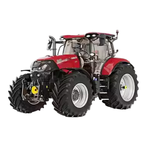
Case 9100 Series User manual

9100 Series Tractor
Service Manual
Table of Contents
Description Section No.
General Tab 1
Safety Suggestions ................................................................................................................. .
Metric Conversion ......................................................................... ,......................................... .
Torque Values ......................................................................................................................... .
Specifications and Capacities
9110, 9130, Puma and Wildcat. .......................................................................................... .
9150, Bearcat and Cougar .................................................................................................. .
9170, 9180, PIN 17900699 and After
Panther and Lion PIN 17900255 and After ..................................................................... .
Panther and Lion Prior to PIN 17900255 ........................................................................... ..
Specifications, Engine 6-830 ................................................................................................... 1426
Engines9110, 9130, Pumaand WildcatOnly Tab 2
Aftercooler ................................................................................................................................ 2011
Cylinder Head and Valve Train ................................................................................................ 2415
Cylinder Block - Camshaft, Pistons, Rods, Sleeves,
Bearings, Camshaft, Seals and Flywheel ............................................................................ 2425
Lubrication System - Oil Pan, Oil Pump, Oil Cooler
and Oil Filter Housing .......................................................................................................... 2445
Cooling System - Thermostat, Water Pump, Fan Pulley
and Belt Tensioner ............................................................................................................... 2455
Turbocharger ............................................................................................................................ 2465
Turbocharger Failure Analysis ................................................................................................. 2565
FuelSystem9110, 9130, Pumaand WildcatOnly Tab 3
Fuel System and Filters ........................................................................................................... 341O
Injection Pump - Pump Drive Gear, Timing Pin,
Fuel Shutoff Solenoid and Primer Pump ............................................................................. 3412
Fuel Injectors ............................................................................................................................ 3413
Electrical Tab 4
Wiring Schematics
9110 and 9130 PIN 17900564 and Below
9150 PIN 17900705 and Below
Puma PIN 17900250 and Below
BearcaVCougar PIN 17900270 and Below .................................................................... ..
9110 and 9130 PIN 17900564 and After
9150 PIN 17900705 and After
9170 and 9180 PIN 17900669 and After
Puma PIN 17900250 and After
Wildcat PIN 1790001 and After
BearcaVCougar PIN 17900270 and After
Panther/Lion PIN 17900255 and After............................................................................. .
9170/9180 SN 17900150
Panther/Lion SN 6501 and After...................................................................................... .
Solid State Electronic Dash and ROPS Instrument Panel....................................................... 4003
Alternators
Niehoff Model N1056 .......................................................................................................... .
Motorola LHB Series .......................................................................................................... ..
IReprintedI
Rae 8-91571
CASE CORPORATION
Form No.
M00103
M00104
M00105
37-189
37-156
37-188
37-175
8-28421
8-91700
8-28430
8-28440
8-28450
8-28460
8-28470
9-78235
8-28480
8-28490
8-28500
37-16OR1
37-187
37-178
8-81130
37-155
37-169
Printed in U.SA
December. 1989

9100 Series Tractor
Service Manual
Table of Contents
Description Section No.
Steering Tab ·s
Steering Column ......................................................................................................................
Steering Control Unit................................................................................................................
Front Axle Steering................................................................................................................... 5001
PowerTrain Tab 6
Controlled Traction Electric Shift Unit......................................................................................
K598-60/70 and K598-64/74 Axle............................................................................................
K598-60/70 Axle ("NOK" Seal)................................................................................................. 6002
AP3445 Axle.............................................................................................................................
K592-20/30 Axle....................................................................................................................... 6003
EW-16 Powershift Transmission, Removal and Installation ....................................................
EW-16 PowerShiftTransmission, Repair .................................................................................
Powershift Transmission Charge Pump .................................................................................. 6012
PTO Drive Unit ........................................................................................................................ .
Brakes Tab 7
Caliper Disc Brake System ......................................................................................................
Hydraulics Tab 8
Hydraulic Specifications and Schematics ........................................................................... ..
Three Point Hitch Alignment and Valve Service...................................................................... 8021
Chassis Tab 9
Cab Removal and Installation................................................... ............................................
Heating, Ventilating, Air Conditioning 9110, 9130, 9150,
Puma, Wildcat, Bearcat and Cougar ...................................................................................
Heating, Ventilating, Air Conditioning 9170, 9180, Panther and Lion.....................................
Air Ride Seat............................................................................................................................
How It Works Tab 10
Rae 8-91571
Form No.
37-093
37-153
8-81100
M0100
37-163
8-81090
37-171
8-81120
37-174
37-168
8-81660
37-170
37-179
37-166
8-81670
37-172
37-177
37-136
37-180
Printed ,n U SA
December. 1989
Find manuals at https://best-manuals.com

HAND SIGNALS
For communication under noise conditions and special operations the American Society of
Agricultural Engineers has made standard agricultural hand signals. You will find that the
hand signals can decrease time loss and prevent accidents.
Start The Engine
Start the engine. Move arm in a circle at belt level.
Stop The Engine
Stop the engine. Move your right arm across your
neck from left to right.
Move Toward Me - Follow Me
<
Move toward me or follow me. Look toward person
or vehicle you need to move. Hold one hand in front
of you with the back of the hand toward the vehicle
and move your arm from the elbow to the fingers
backward and forward.
M00103
This Far To Go
I
This far to go. Put your hands in front of your face
with the back of your hands outward. Move your
hands in or out as an indication how far to go.
Move Out
Move out. Face in the needed direction of movement.
Put your arm straight out behind you. Then, swing
your arm over your head and forward until your arm
is straight out in front of you with the back of your
hand up.
Printed in U.S.A.
Find manuals at https://best-manuals.com

HAND SIGNALS
Come To Me
Come to me (can also be come to me because I need
assistance). Lift your arm vertically over your head
with the back of your hand to the rear and turn your
arm in large horizontal circles.
Decrease Speed
Decrease speed. Put your arm out horizontally with
the back of your hand up and then move your arm
down about 45 degrees minimum many time. Keep
your arm straight and do not move your arm above
your shoulder.
Increase Speed
•
n
Increase speed. Lift your hand to shoulder level with
your fingers closed. Move your closed hand fully up
and then return to shoulder level. Do this fast, many
times.
M00103
Raise Equipment
Raise equipment. Point up with one finger and at the
same time, move your hand in a circle at head level.
Lower Equipment
Lower equipment. Point to the ground with one
finger and at the same time move your hand in a
circle.
Stop
Stop. Raise your arm fully up with the back of your
hand to the rear. Keep this position until the signal is
understood.
Printed in U.S.A.
Find manuals at https://best-manuals.com

Safety Suggestions
The manufacturer, dealer and/or agent can not
anticipate every possible circumstance that might
involve potential hazard. The Warnings, Cautions
and Safety Suggestions in this manual are therefore
not all inclusive. If an operating procedure, tool
device, maintenance or work method not specif-
ically recommended is used, you must also ensure
that the product will not be damaged or made
unsafe by the procedures you choose.
A Whenever you seethis symbol, it means
Attention! Become Alert! Your safety is
involved.
• Always observe and heed all caution and
warning signs or other decals wherever they
may appear.
• Always install the locking bar between the front
and rear frames whenever possible -
A. Before service work is done near center of
tractor
B. Before lifting or transporting the tractor on
another vehicle
C. Before operating stationary PTO driven equip-
ment
• Never perform any service or maintenance in
the center hinge area of a 4 wheel-drive articu-
lated tractor unless the engine is shut off and the
switch key removed.
• Never clean, service or adjust the tractor or any
equipment operated by it until the tractor engine
is shut down and all machine motion is stopped,
unless specific instructions are given for a
particular repair or procedure.
• Always direct compressed air away from the
body and towards a safe area. Use only an
approved air nozzle and wear adequate eye
protection.
• Always keep hand tools in good condition and
proper working order. Replace any that are
damaged.
• Always have electrical equipment and cords
serviced and/or inspected periodically. Use only
properly grounded electrical equipment.
• Always keep shop floors dry and clean to pre-
vent falls of people and/or equipment.
M00103
• Always weld and/or grind only in safe areas
away from any flamable or explosive materials.
• Always read the operation instructions and
understand the proper use of test equipment or
other special tooling.
• Always inspect all lift tie chains and/or slings
periodically, replace any that show signs of
damage.
• Always use a rated alloy chain for lifting or a
sling of asize and type adequate fort he intended
usage.
• Always relieve all pressure in air, oil or water
systems before any lines, fittings or related
items are disconnected or removed. Be alert for
possible fluid pressure or spring force when
disconnecting or repairing any device from a
system that utilizes fluid pressure or spring
force.
• Always reinstall all fasteners with the same part
number. Do not use a lessor quality fastener if
replacements are necessary.
• Always wear eye protection when charging,
boosting or performing other services to or
around batteries.
• Never spin or rotate bearings with compressed
air.
• Never attempt to lift or jack an object that
exceeds the weight capacity of the lifting fixture
(jack, hoist, fork lift etc.).
• Never wear loose fitting clothing around rotating
shafts or machinery. Long hair should always be
netted.
• Do not try to locate high pressure fluid leaks
with your hands. Use cardboard or wood to
search for suspected leaks. High pressure fluid
escaping from a very small area can be nearly
invisible. If injured by high pressure fluid, seek
immediate medical attention. Serious infection
or reaction can develop if proper medical treat-
ment is not administered immediately.
• Do not use unguarded grinding tools or other
power tools requiring a guard. Wear safety
glasses and safety shoes whenever they may be
required.
Printed in U.S.A.
Find manuals at https://best-manuals.com

• Do not
attempt to separate or disassemble
hydraulic cylinders with the use of compressed
air or hydraulic pressure.
• Do not
attempt tire repairs unless you have the
proper equipment and know how to perform the
repair correctly and safely.
• Do not
work on anything that is supported only
by lift jacks or a hoist. Always use adequate
blocks or proper stands to support the product
before performing any service work.
• Use only approved cleaning solvents. Never use
gasoline or other flam able or explosive materials
for cleaning.
• Report or correct any unsafe areas or practices
immediately.
• Before doing any electrical work, disconnect
the battery. Do not damage wiring during
removal operations. Reinstall the wiring so it is
not damaged nor will it be damaged in operation
by contacting sharp corners, or by rubbing
against objects or sharp corner.
• If guards or.shields must be removed to perform
the repair or service, use extra caution. After the
repair is completed, be sure to reinstall any
quard or shield that was removed.
These are a few of the most common causes of
personal injuries. There are a great many more and
shops are continually finding accidents happening
that they never heard of before.
The only known way to reduce personal injury, is to
teach and practice Safety First.
Printed in U.S.A.
Find manuals at https://best-manuals.com
Metric Conversion
Conversion Table
To Convert Into Multiply By To Convert Into Multiply By
mm in.
.03937 in. cu 2.54
cm in. .3937 in. m .0254
m in. 39.37
CU.
in. cc 16.39
cc cu in. .06102 gal. liter 3.785
liter gal. .2642 qt liter .9463
liter qt 1.057 oz g 28.349527
g oz .03527 lb g 453.5924
kg-m ft-lb 7.235 ft-lb kg-m .1383
N.m ft-lb .7374 ft-lb N.m 1.356
psi bar 0.06896 bar psi 14.5
HP
Kw
.07457
kw HP
1.341
L cu in. 61.02 cu in. L 0.01639
in. mm 25.40
Conversion• Common Fractions to Decimals and Millimeters
INCHES TO CENTIMETERS AND
CENTIMETERS TO INCHES
Inches Inches
or Centi- or Centi-
Centi- Inches meters Centi- Inches meters
meters meters
1 0.39 2.54 26 10.24 66.04
2 0.79 5.08 27 10.63 68.58
3 1.18 7.62 28 11.02 71.12
4 1.57 10.16 29 11.42 73.66
5 1.97 12.70 30 11.81 76.20
6 2.36 15.24 31 12.20 78.74
7 2.76 17.78 32 12.60 81.28
8 3.15 20.32 33 12.99 83.82
9 3.54 22.86 34 13.39 86.36
10 3.94 25.40 35 13.78 88.90
11 4.33 27.94 36 14.17 91.44
12 4.72 30.48 37 14.57 93.98
13 5.12 33.02 38 14.96 96.52
14 5.51 35.56 39 15.35 99.06
15 5.91 38.10 40 15.75 101.60
16 6.30 40.64 41 16.14 104.14
17 6.69 43.18 42 16.54 106.68
18 7.09 45.72 43 16.93 109.22
19 7.48 48.26 44 17.32 111.76
20 7.87 50.80 45 17.72 114.30
21 8.27 53.34 46 18.11 116.84
22 8.66 55.88 47 18.50 119.38
23 9.06 58.42 48 18.90 121.92
24 9.45 60.96 49 19.29 124.46
25 9.84 63.50 50 19.69 127.00
How to use:
11
inches= 27.94 centimeters -11 centimeters= 4.33 inches
M00104
Inch And Millimeter Decimal Equivalents
Of Fractions Of An Inch
Inch Millimeter Inch Millimeter
1/64 0.015625 0.396875 33/64 0.515625 13.096875
1/32 0.031250 0.793750 17/32 0.531250 13.493750
3/64 0.046875 1.190625 35/64 0.546875 13.890625
1/16 0.062500 1.587500 9/16 0.562500 14.287500
5/64 0.078125 1.984375 37./64 0.578125 14.684375
3/32 0.093750 2.381250 19/32 0.593750 15.081250
7/64 0.109375 2.778125 39/64 0.609375 15.478125
1/8 0.125000 3.175000 5/8 0.625000 15.875000
9/64 0.140625 3.571875 41/64 0.640625 16.271875
5/32 0.156250 3.968750 21/32 0.656250 16.668750
11/64 0.171875 4.365625 43/64 0.671875 17.065625
3/16 0.187500 4.762500 11/16 0.687500 17.462500
13/64 0.203125 5.159375 45/64 0.703125 17.859375
7/32 0.218750 S.556250 23/32 0.718750 18.256250
15/64 0.234375 5.953125 47/64 0.734375 18.653125
1/4 0.250000 6.350000 3/4 0.750000 19.050000
17/64 0.265625 6.746875
49/64
0.765625 19.446875
9/32 0.281250 7.143750 25/32 0.781250 19.843750
19/64 0.296875 7.540625 51/64 0.796875 20.240625
5/16 0.312500 7.937500 • 13/16 0.812500 20.637500
21/64 0.328125 8.334375 53/64 0.828125 21.034375
11/32 0.343750 8.731250 27/32 0.843750 21.431250
23/64 0.359375 9.128125 55/64 0.859375 21.828125
3/8 0.375000 9.525000 7/8 0.875000 22.225000
25/64 0.390625 9.921875 57/64 0.890625 22.621875
13/32 0.406250 ·10.318750 29/32 0.906250 23.018750
27/64 0.421875 10.715625 59/64 0.921875 23.415625
7/16 0.437500 11.112500 15/16 0.937500 23.812500
29/64 0.453125 11.509375 61/64 0.953125 24.209375
15/32 0.468705 11.906250 31/32 0.968750 24.606250
31/64 0.484375 12.303125 63/64 0.984375 24.003125
1/2 0.500000 12.700000 1 1.000000 25.400000
To Convert: Inches to Millimeters -Multiply Inch Value by 25.4
Millimeters to Inches -Divide Millimeter Value by 25.4
1
Inch
=
25.4 Millimeters (mm) EXACTLY
Printed in U.S.A.
Find manuals at https://best-manuals.com

Conversion - Millimeters To Decimal Inches
To change decimal millimeters to decimal inches, mm into decimal inches, reset the decimal behind
position the decimal point where desired on either the 1 mm (shown on the chart) to 0.001; change the
side of the millimeter measurement shown and reset decimal inch equivalent (0.039 inch shown) to
the inches decimal by the same number of digits in 0.00039 inch.
the same direction. For example, to convert 0.001
.!Jl!!! inches
1 0.039370 41 1.614170 81 3.188970 210 8.267700
2 0.078740 42 1.653540 82 3.228340 220 8.661400
3 0.118110 43 1.692910 83 3.267710 230 9.055100
4 0.157480 44 1.732280 84 3.307080 240 9.448800
5 0.196850 45 1.771650 85 3.346450 250 9.842500
6 0.236220 46 1.811020 86 3.385820 160 10.236200
7 0.275590 47 1.850390 87 3.425190 270 10.629900
8 0.314960 48 1.889760 88 3.464560 280 11.032600
9 0.354330 49 1.929130 89 3.503903 290 11.417300
10 0.393700 50 1.968500 90 3.543300 300 11.811000
11 0.433070 51 2.007870 91 3.582670 310 12.204700
12 0.472440 52 2.047240 92 3.622040 320 12.598400
13 0.511810 53 2.086610 93 3.661410 330 12.992100
14 0.551180 54 2.125980 94 3.700780 340 13.385800
15 0.590550 55 2.165350 95 3.740150 350 13.779500
16 0.629920 56 2.204720 96 3.779520 360 14.173200
17 0.669290 57 2.244090 97 3.818890 370 14.566900
18 0.708660 58 2.283460 98 3.858260 380 14.960600
19 0.748030 59 2·.322830 99 3.897630 390 15.354300
20 0.787400 60 2.362200 100 3.937000 400 15.748000
21 0.826770 61 2.401570 105 4.133848 500 19.685000
22 0.866140 62 2.440940 110 4.330700 600 23.622000
23 0.905510 63 2.480310 115 4.527550 700 27.559000
24 0.944880 64 2.519680 120 4.724400 800 31.496000
25 0.984250 65 2.559050 125 4.92125'0 900 35.433000
26 1.023620 66 2.598420 130 5.118100 1000 39.370000
27 1.062990 67 2.637790 135 5.314950 2000 78.740000
28 1.102360 68 2.677160 140 5.511800 3000 118.110000
29 1.141730 69 2.716530 145 5.708650 4000 157.480000
30 1.181100 70 2'.755900 150 5.905500 5000 196.850000
31 1.220470 71 2.795270 155 6.102350
32 1.259840 72 2.834640 160 6.299200
33 1.299210 73 2.874010 165 6.496050
34 1.338580 74 2.913380 170 6.692900
35 1.377949 75 2.952750 175 6.889750
36 1.417319 76 2.992120 180 7.086600
37 1.456689 77 3.031490 185 7.283450
38 1.496050 78 3.070860 190 7.480300
39 1.535430 79 3.110230 195 7.677150
40 1.574800 80 3.149600 200 7.874000
M00104 Printed in U.S.A.
Find manuals at https://best-manuals.com

Recommended Maximum Torque Values
Use the following torques when special torques are not listed
(Grade 2) (Grade 5) (Grade 6) (Grade 8)*
Torque Torque Torque Torq_ue
Inch (threads) Ft Lbs (N.m) Ft Lbs (N.m) Ft Lbs (N.m) Ft Lbs (N.m)
Size Lubricated Lubricated Lubricated Lubricated
1/4 (20) 4 (5.4) 6 (8.1) 8 (10.8) 9 (12.2)
1/2 (28) 5 (6.8) 7 (9.5) 9 (i2.2) 11 (14.9)
5/16 (18) 8 (10.8) 13 (17.6) 16 (21.7) 18 (24.4)
5/6 (24) 10 (13.5) 15 (20.3) 18 (24.4) 21 (28.5)
3/8 (16) 15 (20.3) 24 (32.5) 29 (39.3) 34 (46)
3/8 (24) 17 (23) 27 (36.6) 33 (44.8) 38 (51.5)
7/16 (14) 25 (40) 38 (51.5) 47 (63.7) 54 (73.2)
7/16 (20) 27 (36.6) 42 (56.9) 52 (70.5) 60 (81.3)
1/2 (13) 38 (51.5) 58 (78.6) 72 (97.6) 82 (111.2)
1/2 (20) 42 (57) .65 (88.1) 80 (108.5) 90 (122)
9/16 (12) 54 (73) 84 (113.9) 105 (142.4) 120 (162.7)
9/16 (18) 60 (81.4) 93 (126.1) 115 (156) 132 (179)
5/8 (11) 71 (96) 115 (156) 145 (197) 165 (224)
5/8 (18) 81 (110) 130 (176) 160 (217) 185 (251)
3/4 (10) 125 (169) 205 (278) 250 (339) 290 (393)
3/4 (16) 140 (190) 230 (312) 280 (380) 320 (434)
7/8 (9) 108 (146) 305 (414) 405 (549) 455 (617)
7/8 (14) 120 (163) 335 (454) 450 (610) 515 (698)
1 (8) 163 (221) 455 (617) 610 (827) 695 (942)
1 (14) 178 (241) 510(691) 685 (929) 1785 (1064)
1-1/8 (7) 230 (312) 610 (827) 865 (1173) 990 (1342)
1-1/8 (12) 260 (353) 685 (929) 970 (1315) 1110 (1505)
1-1/4 (7) 325 (441) 860 (1166) 1225 (1661) 1400 (1898)
1-1/4 (12) 360 (488) 955 (1295) 1355 (1837) 1500 (2102)
1-3/8 (6) 425 (576) 1130 (1532) 1600 (2170) 1830 (2481)
1-3/8 (12) 480 (651) 1290 (1749) 1830 (2481) 2085 (2827)
1-1/2 (6) 565 (766) 1500 (2034) 2130 (2888) 2430 (3295)
1-1/2 (12) 635 (861) 1690 (2291) 2400 (3254) 2730 (3702)
1-3/4 (5) 765 (1037) 2370 (32.14) 3360 (4556) 3840 (5207)
2 (4.5) 1310 (1776) 3550 (4814) 5050 (9286) 5760 (7811)
NOTE: These values apply to fasteners as received from ·Thick Nuts must be used
the supplier, dry, or when lubricated with normal engine with Grade 8 bolts.
oil. They do not apply if special graphited or moly-
disulphide greases or other extreme pressure lubricants
are used. This applies to both UNF and UNC threads.
M00105 Printed in U.S.A.
Find manuals at https://best-manuals.com
37-189 {2M, 10-87)
GENERAL SPECIFICATIONS
AND CAPACITIES
Case IH 9110 and 9130 Series
P.I.N. 17900564 and After
Steiger Puma 1000 Series
P.I.N. 17900250 and After
Steiger Wildcat 1000 Series
P.I.N. 17907001 and After
Service Manual
CASE CORPORATION
Issued October, 1987
Printed in U.S.A.

Contents
Axle ................................................................. 1
Brakes .............................................................. 1
Cab ................................................................. 2
Fuel System ........................................................ 2
Electrical ........................................................... 3
Transmission ....................................................... 3
Hydraulic System .................................................. 4
3-Point Hitch ....................................................... 4
PTO System ........................................................ 4
Engine .............................................................. 5
Shipping Weight & Warranted Weight ............................ 6
Speed Chart ........................................................ 6
Frame Dimensions ................................................. 7
Tire Loads & Inflation Pressures .................................. 8
Ballast .......................................................... 9, 10
Tread Setting Dimensions .................................... 10-13
Wheel Adjustment Procedure ................................ 13, 14
Torque Values ................................................ 15-17
Issued October, 1987
37-189
Printed in U.S.A.

IMPORTANT: All fluid capacities list-
ed throughout this section are a guide
to the quantities required. Always
use dipsticks or level plugs to ensure
that the units are filled to the correct
level.
Figure 1: AP-3445 Axle
Figure 2: K592 Axle
Figure 3:
Issued October, 1987
37-189 1
General Specifications
Axle (Puma and 9110)
Model: AP-3445 Adjustable Bar (front & rear
torque proportional limited slip differential)
Type: Single reduction inboard planetary, spiral
bevel ring gear and pinion
Bar Diameter: 4.0 in. (10.16 cm)
Axle Length: 119.5 in. (303.5 cm)
Wheel Spacing: Adjustable from 60.0 in. (152.4
cm) to 130.0 in. (330.2 cm)
Ratio: 26.15:1
Oil Capacity: 8.0 US gal. (30.2 L)
Oil Type: HD 80W-90 gear oil or other quality
oils that meet API classification GL-5 and/or
MII-L-2105B military specifications
Axle (Wildcat and 9130)
Model: Raba K592 Ajustable Bar
Type: Single reduction inboard planetary, spiral
bevel ring gear and pinion
Bar Diameter: 4.0 in. (10.16 cm)
Axle Length: 119.5 in. (303.5 cm)
Overall Ratio: 25.294:1
Wheel Spacing: Adjustable from 60.0 in. (152.4
cm) to 130.0 in. (330.2 cm)
Oil Capacity: 11.75 US gal. (44.5 L)
Oil Type: HD 80W-90 gear oil or other quality
oils that meet API classification GL-5 and/or
MII-L-2105B military specifications
Brakes
Type: Hydraulic, self-adjusting single caliper,
dual piston, disc brake
Disc Diameter: 15 in. (38.1 cm)
Mounting: Transmission
Park Brake: Integral with service brake caliper,
hand operated, cable actuated
Master Cylinder: Hydraulic
Fluid Type: SAE-J1703D or DOT-3 brake fluid
Fluid Capacity: 1 qt (0.946L)
Disc Resurfacing Limits: 0.015 in. (0.38 mm)
maximum per side
9110, 9130, Puma/Wildcat 1000 Specifications
Printed in U.S.A.

General Specifications
Cab
ROPS: Four post design certified to OSHA-
29CFR 1928subpart C and/or ASAE S383, SAE
J1194 to 44,000 lb (19,958 Kg) and CSA B352-
M1980 clause 5@ 44,000 lb.
Mounting: Rubber isolator (4)
Glass: Tinted-all
Access Door: Left hand; damper used for
opening
Seat: Mechanical deluxe, fabric covered cush-
ion, swiveling, fully adjustable (air suspension
optional).
Radio:Optional AM/FM stereo or AM/FM stereo
cassette
Steering Wheel: Tilt/Telescoping type column
Climate Control: Constant flow cab pressuriza-
tion, A/C and heating, aspirated cab air intake
filtration system
Instruments: Centralized solid state electronic
dash display with function indicator lights and
digitized LCD readouts for MPH, Engine and
PTO rpm and gear selected. ROPS post gauge
panel for hourmeter, fuel level, voltmeter,
engine coolant temperature, engine and trans-
mission oil pressure.
Windshield Wipers: electric front center (std)
Fuel System
Capacity: 115 US gals. (435L), integral with
rear frame
Fuel Type: Grade No. 1Dor Grade No. 2D fuel
as defined by ASTM designation D975 for
Diesel Fuels.UseNo.2D when ambient tempera-
tures are consistantly above 32° F (0° C).
Issued October, 1987
37-189
Figure 4:
2 9110, 9130, Puma/Wildcat 1000 Specifications
Printed in U.S.A.

Figure 6:
Figure 7:
IMPORTANT: Do not use multi-viscosity oil. Check
transmission oil level once every ten hours of
operation. Check oil level only after engine has been
stopped for at least 30 minutes and tractor is parked
on a level surface. Fill only to full mark on the
dipstick. Do not overfill.
Issued October, 1987
37-189 3
General Specifications
Electrical
Type: Parallel 12 volt, negative ground system
Batteries: Two (2) 12 volt. 1250 CCA @ 0° F
(-17.8° C) 625CCA per battery@0° F(-17.8° C)
Alternator: 105amp with built-in regulator
Engine Block Heater: 750 watt, 110 volt
Ether Start Aid: Optional
Starter: 12 volt negative ground, solenoid acti-
vated positive engagement
Lighting: Six (6) halogen sealed beam lights
(four front and two rear); 2 rear reflectors.
Hazard flasher with integral turn signals. Rear
remote electrical receptacle, one cab dome
light. Diagnostic warning lights and back lighting
of dash readout, eyebrow lighting of overhead
console and right side control console.
Hourmeter: RPM actuated (300 rpm minimum)
Tractor Monitor System: Audio warning alarm
and indicator warning lights for both critical and
non-critical functions.
Circuit Breakers:Automatic reset type
Overhead Console: Drop down type for access
to electrical circuitry
Bulb or Lamp Replacement
Front Headlamps (65W high - 35 low) No. H6054
Front & Rear Flood Lamps (60W) P/N 20-1822T1
Electronic Dash lndiator Bulbs No. 194
Overhead Console Bulbs No. 53
Right Side Control Console Bulbs P/N 20-1384T1
ROPS Post Gauge Panel Bulbs No. 1893
Stop/Tail Lamp Bulb No. 1157
Cab Dome Lamp Bulb No. 1141
Hazard Flasher Lamp Bulb No. 1156
Transmission
Type: Powershift
Model: EW16
Speeds: 12 forward, 2 reverse
Master Clutch: Wet hydraulic type, integral
with transmission. Modulated engagement,
pressure lubricated and oil cooled.
Oil Type: Hydraulic/Transmission oil, blended
to JDM J20B orequivelant. DO NOT use multi-
viscosity oils.
Oil Capacity: 9 US gal. (34.0L) approx
Always allow transmission fluid ample time to warm
up following engine startup before shifting out of
neutral when ambient temperatures fall to 40° F (S0
C) or lower. If temperatures remain consistently
below 40° F (S° C) oil blended to JDM J20A or
equivelant is acceptable.
9110, 9130, Puma/Wildcat 1000 Specifications
Printed in U.S.A.

General Specifications
Hydraulic System
Type:
Closed center, load sensing, pressure
compensating
ReservoirCapacity:
18.0 US gals. (68.0L). Pres-
surized to 5 psi (34.45 kPa) and 225°F (105° C)
warning sensor.
Steering:
Articulated, full priority, load sensing
hydrostatic with 2 double acting cylinders
Front Steer Axle (Optional)
Type:
Single double acting cylinder, operated
from load sensing hydrostatic steering con-
trol valve. Provides 6° left/right front axle
turning capability. Micro-processor controlled
system.
Remote Control Valve:
Closed center, stack
type. Remote mounted and direct linkage actu-
ated. Detented in the working position with
hydraulic kick-outs. Individual section float
positions and flow control; 2 to 27 gpm (7.6 to
102.2 L/min)
System Operating Pressure:
2500 psi (172.4
bar, 17,225 kPa) maximum
Pump Capacity:
Approx 27 gpm (102.2 L/min)
@2100 rpm
Filtering System:
Eight micron special micro-
glass element. Suction screen inside reservoir
Oil Type:
Hytran Plus Hydraulic/Transmssion
fluid, or 10W Antiwear Hydraulic Fluid
Couplers:
ISO standard, lever type couplers
and male tips
3-Point Hitch (Optional)
Type:
Category Ill free-link hitch - meets or
exceeds SAEJ715 standards for attachment to
Category Ill implements. Lift capacity 24 in.
(61 cm) behind draft arm uniball - 10,000 lbs
(4540 kg)
Quick-Coupler:
Category
111,
meets or exceeds
SAE-J909b standards for attachment to Cate-
gory Ill implements.
PTO System (Optional)
Type:
Live and independent system integral
with transmission. Lever actuated, hydraul-
ically operated wet clutch with integral hydraul-
ically applied brake when control is shut-off.
Shaft turns free when engine is shut off.
Speed:
1000 rpm @2100 engine rpm
Output Shaft:
1.75 in. (4.4 cm) diameter, 20
splines and flip-up shield
Lubrication Type:
SAE
1
OW30
Capacity:
1.7 US qts (1.6 L)
Issued October, 1987
37-189
4
I
FILTER
FRONT AXLE
STEERCYL
(OPTIONAL)
\
Figure B:
Figure 9:
Figure 10:
HEAT
-EXCHANGER
LOAD
--SENSE
CHARGE
PUMP
I
PISTON
PUMP
STEERING
CYLINDER
\
"-.CHARGE PRESSURE
CONTROL VALVE
HYDRAULIC
RESiRVOIR
-STEERING
CYLINDER
9110, 9130, Puma/Wildcat 1000 Specifications
Printed in U.S.A.

General Specifications
Engine Left Side
1-Coolant Surge Tank 6-Fuel Shutoff Solenoid
2-A/C Compressor 7-Water Separator
3-Fuel Injection Pump 8-Fuel Filter
4-Ether Start 9-Fuel Lift Pump
5-Engine Air Cleaner 10-Oil Fill
Engine
TractorModel Puma
and
9110
EngineMake Case
Type In-Line 6
Model 6T830
Displacement 504.5 cu in. (8.27L)
RatedHorsepower 190 (141.5 Kw)
RatedRPM(R/min) 1700-2100
HighIdle(noload) 2310 approx
Lowidle 850 approx
OperatingTorque(2100rpm) 475 ft lb (644 N.m)
TorqueRise 30%
Engine Right Side
1-Coolant Heater
2-Starter 4-Coolant Filter
5-Oil Drain
6-Alternator
3-Oil Filter
Wildcat
and
9130
Case
In-Line 6
6TA830
504.5 cu in. (8.27L)
220 (163.9 Kw)
1700-2100
2310 approx
850 approx
550 ft lb (746 N.m)
30%
Bore& Stroke 4.49 x 5.32 in. (114 x 135 mm) 4.49 X 5.32 in. (114 X 135
CompressionRatio 16.5:1 16.5:1
FiringOrder 1-5-3-6-2-4 1-5-3-6-2-4
ValveSetting(cold) Intake - 0.012 in. (0.30 mm) Intake - 0.012 in. (0.30 mm)
Exhaust - 0.024 in. (0.61 mm) Exhaust - 0.024 in. (0.61 mm)
OilCapacity(includesfilters) 23.7 US qts (22.4L) 23.7 US qts (22.4L)
CoolantCapacity 35 US qts (33.1L) 35 US qts (33.1L)
OilPressure(minimum) Low idle 10 psi (69 kPa) Low idle 10 psi (69 kPa)
High idle 30 psi (207 kPa) High idle 30 psi (207 kPa)
Lubricating Oil: Use multi-viscosity, preferable 15W-40 meeting API Classification CC/CD
NOTE: 10W-30 may be used in ambients consistantly below 23°F (-5° CJ.
Issued October, 1987
37-189 5 9110, 9130, Puma/Wildcat 1000 Specifications
Printed in U.S.A.

General Specifications
Approximate Shipping Weight
Puma 1000 & 9110
18,879 lbs. (8,571 Kg) with 18.4 x 38 R1 (6 ply)
singles, PTO and steerable front axle less fuel and
operator. Add 1736 lb (788 Kg) for TPH and Quick
Coupler.
Wildcat 1000 and 9130
25,022 lbs. (11,334 Kg) with 18.4 x 38 R1 Hub Style
Duals. 21,530 lbs. (9,775 Kg) with 18.4 x 38 R1
singles. Front steer axle, PTO and TPH with Quick
Coupler, less fuel and operator.
Speed Chart
Engine RPM: 2100
Transmission: Powershift
Puma and 9110 Wildcat and 9130
Gear MPH (KPH) Gear MPH (KPH)
1 1.9 (3.1) 1 2.0 (3.3)
2 2.3 (3.7) 2 2.5 (3.9)
3 2.9 (4.7) 3 3.0 (4.9)
4 3.5 (5.6) 4 3.7 (5.9)
5 4.2 (6.7) 5 4.4 (7.1)
6 5.1 (8.2) 6 5.5 (8.8)
7 6.2 (9.9) 7 6.5 (10.5)
8 7.4 (11.9) 8 7.8 (12.5)
9 9.1 (14.6) 9 9.6 (15.4)
10 11.2 (18.0) 10 11.7 (18.9)
11 13.4 (21.5) 11 14.1 (22.7)
12 16.5 (26.5) 12 17.3 (27.9)
R1 2.5 (4.0) R1 2.7 (4.3)
R2 4.6 (7.4) R2 4.8 (7.8)
Speeds shown represent following tire sizes at rated
rpm (2100):
18.4 X 38 R1
24.5 x 32 LS2 23.1 x 34 R1
20.8 X 38 R1 24.5 x 32R1
30.5L x 32 R1
To determine speed for other tire sizes use the
following chart multipliers:
Average Static
Loaded R.R. Tire Size Factor
30.5 14.9x38 .96
30.5 16.9 X 38 .96
30.7 20.8 x 34 R1 .96
33.5 20.8 X 38 R2 1.05
33.7 18.4x42R1 1.05
34.6 20.8 x 42 R1 1.09
33.0 30.5L x 32 R2 1 03
32.5 30.5L x 32 LS2 1.02
Example of Use:
If chart speed was 14.6 MPH and tractor was equipped
with 20.8 x 34 R1 tires,
Then: MPH = (Chart) x (Factor)
MPH = 14.6 x .96 = 14.0 MPH
Issued October, 1987
37-189 6
Maximum Warranted Weight
24,000 lbs. (10,896 Kg) Puma and 9110
26,000 lbs. (11,778 Kg) Wildcat and 9130
NOTE: The maximum warranted weight listed is the
maximum ballasted GVW with a 60% front and 40%
rear static split.
Tire And Ground Speed Data
There are many variables to consider when deter-
mining ground speed. For example, the rolling radii
of tires are not absolute values, on some tire sizes
there could be as much as 3% variation between tire
manufacturers. The indicated values shown are
static dimensions; dynamic values cannot be used
because they vary with tractor weight, weight trans-
fer, soil conditions and tire air pressure. These
variables can account for another 3-5% variation. In
addition, normal field operations are performed
with 10-15% slip.
With all of these variables considered, the published
ground speed chart is for reference only. Use the
chart provided with multiplier factors for the various
tire sizes and engine speeds if more precise speed
data is required.
NOTE: Variable ground speeds are possible with
high torque rise engines within 2100 rpm and 1700
rpm.
Engine Speeds
If MPH iswanted for engine speeds other than rated,
MPH= MPH (Chart) x Engine RPM
Rated RPM
Example:
If chart speed was 14.6 MPH and tractor has engine
with rated speed of 2100 RPM and MPH wanted at
1800 RPM;
Then: MPH 14.6 x 1800 = 12.5 MPH
2100
9110, 9130, Puma/Wildcat 1000 Specifications
Printed in U.S.A.

119.5
(303.5
cm) 88
_
9
(225.8
cm)
r-_64.3_·1
I...c=(163.2cm)
= = Standard Frame
(with 18.4 x 38 tires)
Centers on
60" to 130"
(152.4 cm to 330.2 cm)
Frame Dimensions
Wheel Base:
82.1 31.5
(208.6
cm) (80.0cm)
120.0 in (304.8 cm) std. frame
124.0 in. (314.9 cm) with front steer
Turning Radius (SAE):
14.0 ft (4.25 m) std. frame
12.8 ft (3.9 m) with front steer
71.62
(181.9
cm)
Ground Clearance at Drawbar: 16.0 in. (40.6
cm)
119.5
(303.5
CIII)
64.3
c:;(163.2 cm•
=
88.9
(225.8cm)
= With
Front Steer Axle
85.6" 31.5
(217.4cm] (80.0cm)
General Specifications
69.38
(176.2
cm)
Frame Articulation: 40° left/right
Frame Oscillation: ±13° (26° total)
± 11° (22° total) w/PTO
1
97.05
(246.5
cm)
129.55
(329.0
cm)
Front Axle Steer (optional): 6° left/right
Specifications are subject to change without prior
notice.
97.05
1246.5
cm)
129.55
(329.0
cm)
71.62 --------
(18l.9cm)
Centers on
60" to 130"
(152.4 cm to 330.2 cm)
Issued October, 1987
37-189 7 9110, 9130, Puma/Wildcat 1000 Specifications
Printed in U.S.A.

General Specifications
Recommended Tire Loads & Inflation Pressures
Tire load limits at cold inflation pressure at 20 mph (32.1) kph) maximum speed
Single Maximum
or TireLoad
@ rated
TireType[ply) Dual Inflation
14.9 x 38 R-1 (6) D 3630 lb@ 20 psi
(1644 Kg)@ (138 kPa)
16.9x38R-1 (6) D 4140 lb@ 18 psi
(1875 Kg)@ (124 kPa)
16.9 Ax 38 R-1* D 4340 lb@ 18 psi
(1966 Kg)@ (124 kPa)
18.4x34R-1 (6) D 4360 lb@ 16 psi
(1975 Kg) @ (110 kPa)
18.4 x 38 R-1, R-2 (6) D 4620 lb@ 16 psi
(2093 Kg)@ (110 kPa)
18.4x38R-1 (8) s 5980 lb@ 20 psi
(2709 Kg)@ (138 kPa)
18.4 R x 38 R-1* s 6000 lb@ 18 psi
(2718 Kg)@ (124 kPa)
18.4x42R-1 (10) s 7360 lb@ 20 psi
(3334 Kg)@ (138 kPa)
18.4 Rx 42 R-1** s 7400 lb@ 24 psi
(3352 Kg)@ (169 kPa)
20.8 x 38 R-1, R-2 (8) s 6820 lb@ 18 psi
(3089 Kg)@ (124 kPa)
20.8 Ax 38 R-1* s 7150 lb@ 18 psi
(3239 Kg)@ (124 kPa)
20.8 x 38 R-1 (10) s (3475 Kg)@ (152 kPa)
23.1 x 34 R-1, R-2 (8) s 7110 lb@16 psi
(3221 Kg)@ (110 kPa)
24.5 x 32 R-1, R-2 (10) s 8700 lb @ 20 psi
(3941 Kg)@ (138 kPa)
24.5 x 32 LS-2 (12) s 9680 lb@ 24 psi
(4385 Kg) @ (169 kPa)
30.5 L x 32 R-1, R-2 (10) s 9120 lb@ 18 psi
(4131 Kg)@ (124 kPa)
30.5 LR x 32 R-1* s 10,500 lb@ 18 psi
(4757 Kg)@ (124 kPa)
30.5 L x 32 LS-2 (12) s (4707 Kg)@ (138 kPa)
NOTE 1: The weight indicated is the maximum
ballasted tractor weight with a 60% front and 40%
rear static split. Maximum CVW is also limited by tire
rating.
NOTE 2: When two numbers appear, they represent
the inflation pressures of the inside main and
outside dual tires respectively.
NOTE 3: Tractor drive tires used in severe service, it
is permissable to increase inflation pressure up to 4
psi (28 kPa) above that shown in the "Maximum
PSI" table with no increase in tire load.
Issued October, 1987
37-189 8
Recommended Maximum Maximum
PSI[kPa) PSI[kPa) GVW
[seeNote
2) (seeNote3) [seeNote
1)
18-16 20-18 24,000 lbs
(124)-(110) (138)-(124) (10,896 Kg)
16-14
(110)-(96)
16-14
(110)-(96)
14-12
(96)-(83)
14-12
(96)-(83)
20
(138)
18
(124)
20
(138)
24
(169)
18
(124)
18
(124)
(138)
16
(110)
16
(110)
16
(110)
16
(110)
16
(110)
(110)
A
18-16 24,000 lbs
(124)-(110) (10,896 Kg)
18 24,000 lbs
(124) (10,896 Kg)
16-14 24,000 lbs
(110)-(96) (10,896 Kg)
16-14 24,000 lbs
(110)-(96) (10,896 Kg)
20 21,500 lbs
(138) (9740 Kg)
18 21,500 lbs
(124) (9740 Kg)
20 24,000 lbs
(138) (10,896 Kg)
24 24,000 lbs
(169) (10,896 Kg)
18 22,500 lbs
(124) (10,192 Kg)
18 24,000 lbs
(124) (10,896 Kg)
(152) (10,896 Kg)
16 24,000 lbs
(110) (10,896 Kg)
16 24,000 lbs
(110) (10,896 Kg)
24 24,000 lbs
(169) (10,896 Kg)
18 24,000 lbs
(124) (10,896 Kg)
18 24,000 lbs
(124) (10,896 Kg)
(138) (10,896 Kg)
WARNING: Use safety cage or chain,
clip on chuck, extension hose, wear
eye protection and stand away from
the tire while inflating to prevent the
possibility of personal injury due to
blowoffs, etc.
9110, 9130, Puma/Wildcat 1000 Specifications
Printed in U.S.A.
Table of contents
Other Case Tractor manuals

Case
Case Farmall 115C User manual

Case
Case 385 Diesel Install guide

Case
Case 130 User manual

Case
Case JX70 User manual

Case
Case CX50 User manual

Case
Case QUANTUM 75F User manual

Case
Case T9.435 Stage IV User manual

Case
Case FARMALL 110A Tier 4B User manual

Case
Case 210 User manual

Case
Case FARMALL 45C Tier 4B User manual
Popular Tractor manuals by other brands

MASSEY FERGUSON
MASSEY FERGUSON 5400 Series manual

Case IH
Case IH FARMALL 65C Operator's manual

Simplicity
Simplicity Sovereign 758 3415S owner's manual

Captain
Captain 273 4WD Operator's manual

Simplicity
Simplicity Landlord DLX Series Dealer setup & adjustment instructions

CAS
CAS CS85 Pro Operator's manual