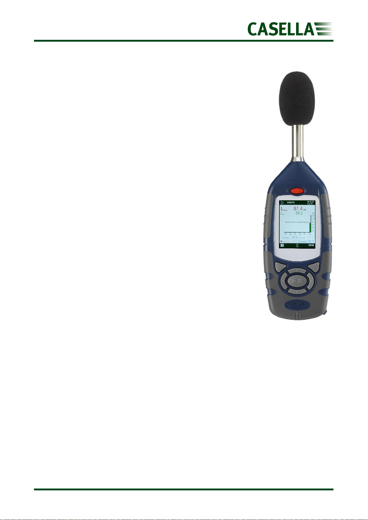
Casella 620 Series User manual

USER MANUAL
www.casellasolutions.com
Casella Holdings Limited
Regent House,
Wolseley Road,
Kempston,
Bedford.
MK42 7JY
T:+44(0) 1234 844 100
F:+44(0) 1234 841 490
620 Series Enhanced Digital
Sound Level Meter
HB3340-03
March 2023

620 Series
2
Contents
Safety and warnings.............................................................................4
Disposal.......................................................................................................... 5
Disclaimer ............................................................................................6
Introduction.........................................................................................7
Instrument features ....................................................................................... 7
Key features ......................................................................................................................7
New features for 2023 ......................................................................................................7
Frequency analysis ............................................................................................................7
Controls ...............................................................................................8
Microphone and pre-amplifier ....................................................................... 9
Soft keys......................................................................................................... 9
Navigation keys............................................................................................ 10
Run/Stop key................................................................................................ 10
Connectivity ................................................................................................. 10
Operation ..........................................................................................11
Batteries....................................................................................................... 11
Turning the instrument On/Off .................................................................... 12
Measurement screens.................................................................................. 13
Main Menu ........................................................................................15
Settings ........................................................................................................ 15
Set UP..............................................................................................................................16
Set Clock..........................................................................................................................16
Language .........................................................................................................................17
Backlight..........................................................................................................................17
Measurement Control.....................................................................................................18
Run Duration ...................................................................................................................19
Calibration reference level..............................................................................................19
Voice Notes .....................................................................................................................20
Memory ....................................................................................................... 20
View Results ....................................................................................................................21

620 Series
3
Delete..............................................................................................................................22
Record Voice Notes.........................................................................................................22
Event data audio .............................................................................................................22
Status ........................................................................................................... 23
GPS Location......................................................................................23
Connectivity.......................................................................................24
Power socket................................................................................................ 24
USB............................................................................................................... 24
Audio socket................................................................................................. 25
System Tools......................................................................................25
Calibration .........................................................................................26
Technical specifications .....................................................................27
Additional information required for testing ......................................28
Declarations.......................................................................................35
Servicing, maintenance and support .................................................36
Servicing....................................................................................................... 36
Support ........................................................................................................ 36
Part numbers and accessories...................................................................... 36
User Notes.........................................................................................37

620 Series
4
Safety and warnings
The 620 series will not present a safety risk when you use it as instructed in this User
Manual. However, it is possible that the environment where you use the instrument may
present a safety risk. For this reason, always follow correct, safe working practices.
WARNING
Always be aware of the risks in the environment where you are working.
•The 620 series is NOT intrinsically safe. DO NOT use it in an atmosphere
where explosive vapours or dusts might exist.
•Wear approved ear defenders when taking measurements in noisy
environments.
•Wear approved protective PPE suitable for the environment where you are
taking measurements.
•Always follow local safety regulations and be aware of risks in the area
where you are working.
CAUTION
The 620 series is a precision instrument. Always handle it with care. Do not drop
the instrument or subject it to mechanical shock.
Do not overtighten the microphone which should only ever be finger tight. Don’t
use pliers to tighten or undo the microphone should it become stuck.
CAUTION
The 620 series contains no user serviceable parts. If a fault is suspected, return
the instrument to Casella or a Casella approved service centre.
CAUTION
The 620 series operate from batteries (or optional mains power).
•Use only batteries of the correct type, and do not mix battery types in the
instrument.
•Do not try to charge non-rechargeable batteries.
•Do not leave discharged batteries in the 620 series.
•Install new batteries as a complete set. Do not fit batteries that have a
mixed state of charge.

620 Series
5
•Remove all batteries from the 620 series if you will not use the instrument
for a long time.
•Always follow local regulations to dispose of used batteries.
CAUTION
The 620 series is not waterproof. Do not immerse the instrument in water or use
it in the rain.
CAUTION
Care should be taken that the operator does not unduly affect the sound field.
Ideally the instrument should be mounted on a sturdy tripod with the microphone
perpendicular to the source of the sound to be measured and the operator should
be as far behind the instrument as possible. If the instrument is to be hand-held,
then the arm of the operator should be stretched out as far as possible to
minimise reflections from the operator’s body.
Disposal
WEEE Notice
At the end of the instrument’s life please do not throw away with the
unsorted municipal waste. Please recycle with a registered WEEE
handler.

620 Series
6
Disclaimer
Do not use the 620 series until you have thoroughly familiarised yourself with this manual or
have been instructed by a Casella engineer. A quick start guide will help you get started.
At the time of writing, this manual was up to date but due to continual improvements the
final operating procedures may differ slightly from those in the manual. If there are any
questions please contact Casella for clarification.
Casella makes continual advancements in its products and services. We therefore reserve
the right to make changes and improvements to any information contained within this
manual.
Whilst every care is taken to ensure that the information in this manual is correct, Casella
will assume no responsibility for loss, damage or injury caused by any errors in, or omissions
from, the information given.

620 Series
7
Introduction
The 620 series is a range of Integrating Sound Level Meters
designed to meet the demands of worldwide industrial health and
safety professionals as well as general noise measurement
applications fully compliant with international application and
instrument standards.
The 620 series is based on the very latest digital signal processing
(DSP) technology and has a colour TFT display with an intuitive user
interface. It encompasses functionality from basic sound level
measurement to integrating and real-time octave band analysis ,
the latter depending on the exact model.
Data is stored in a Comma Separated Variable (.csv) format,
compatible with Microsoft Office applications, and files may be
copied to a PC using a USB connection without the need for any
propriety software packages.
Instrument features
The 620 series comprises several variants, where the letters (A or B)
determine the model variant e.g. A for broadband and B for 1/1
octave band. A chargeable upgrade from A to a B model is
available. Models are available in Class 1 or Class 2 accuracy
signified by a number 1 or 2 (after the letter A or B). See Part
Numbers and Accessories later for more information.
Key features
The 620 series provides A, C, and Z frequency weightings, Fast Slow
and Impulse time weightings with cumulative storage and PC
connectivity functions. A single measurement range of 140dB RMS is standard. Simultaneous
LAeq and LCeq values are measured which may be used in the selection of hearing protection
using the HML method. Lavg (used in the US) is available with a selectable threshold.
New features for 2023
New features for 2023 include audio voice notes, time history profiling and GPS location.
Frequency analysis
‘B Models’provide integrating functionality combined with 1/1 octave band frequency
analysis. Advanced DSP processing provides fast parallel processing of octave band results
from 16Hz to 16kHz which may be displayed graphically or in numerical form and may be A,
C or Z frequency weighted.

620 Series
8
Controls
The 620 series has a compact, ergonomic and robust ‘rubber grip’ case design that fits
comfortably in the hand when not mounted on a tripod. Referring to figure 1 below, the
windshield (1) should be used at all times (except during Calibration) to cover and protect
the microphone, which is screwed onto the fixed pre-amplifier (2).
When the instrument is switched ON by pressing the red key (3) it will run through a
software initialisation and then default to a Stop mode, indicated by a Red Bar at the top and
bottom of the screen.
To navigate ‘within a screen’use the Cursor Keys (6) but note that not all the screens have
navigable fields.
To navigate from one screen to another, use the left and right hand Soft Keys (5).
To start a measurement ‘run’, press the Run/Stop Key (7); to stop the run press the same key
again.
The instrument has a single measurement range of 140dB (RMS) and 143.3dB (C) peak. No
range adjustment is needed which greatly simplifies operation.
The 620 series measures all combinations of required parameters simultaneously with the
required frequency and time weighting.
Figure 1

620 Series
9
Microphone and pre-amplifier
The 620 series has a fixed pre-amplifier and removeable ½ inch (12.7 mm) pre-polarised
microphone. There are two types of microphone available depending on the accuracy Class,
namely:-
•CEL-251 microphone used on Class 1 versions, 50 mV/Pa sensitivity
•CEL-252 microphone used on Class 2 versions, 30 mV/Pa sensitivity
The instrument is supplied with a microphone windshield which provides protection from
both wind and minor mechanical damage and should always be fitted to the microphone
(except during calibration).
Soft keys
The two soft keys (5) shown in figure 1 are located below the corresponding options
displayed at the bottom of each screen. The operation of these two keys change, depending
on which screen is displayed as shown by the overview of the operating system in figure 2.
Figure 2
Generally, you press the soft key on the right to select a function, and press the soft key on
the left to exit a screen or cancel a function.
The instrument screens have been designed with colour coded top and bottom bars to enable
the user to know at a glance which part of the operating system is currently being accessed.

620 Series
10
Colour coding in more detail is as follows in figure 3:
Screen
Colour
Description
Red
Stop screens –These screens are displayed when the instrument has
completed initialisation after power on, as well as before and after taking
measurements.
Blue
Settings screens –These screens are used to set up the instrument correctly
and includes settings such as date and time, language and backlight.
Light
Blue
Memory Results screens –This is where the results from measurements are
viewed.
Green
Run screens –These screens show a measurement is in progress, measured
values are stored in the memory results.
Yellow
Calibration screen –This screen is automatically displayed upon application
of a 1kHz Acoustic Calibrator. This is where the instrument is calibrated
before and after taking measurements.
Figure 3
Navigation keys
The four Navigation keys (6 in figure 1) allow you to select items when highlighted on the
main part of the screen.
Press the , , or navigation key to change to the next selection in the direction of
the cursor arrow.
Run/Stop key
The Run/Stop key (7 in figure 1) allows you to start and to stop a run manually (there is
also a timed run duration timer detailed later).
Connectivity
A rubber cover on the bottom of the instrument reveals an external 12V DC power inlet, USB
socket and Audio output socket described later.

620 Series
11
Operation
This section describes how to use the instrument to take noise measurements using the
minimum of settings.
Once the instrument has been prepared for use, it should be field calibrated as described later
in this section.
Care should be taken that the operator does not unduly affect the sound field. Ideally the
instrument should be mounted on a sturdy tripod with the microphone perpendicular to the
source of the sound to be measured –the operator should be as far behind the instrument as
possible. If the instrument is to be hand-held, then the instrument should be held out as far
as possible to minimise reflections from the operator’s body.
Batteries
To extend battery life, if the 620 series is not taking a measurement and there are no key
presses, the instrument will automatically turn off after a period of 5 minutes. This auto
power off facility is disabled when the 620 series is powered from external 12VDC or USB.
For long term tests, where the batteries may become exhausted, use a 12VDC supply to
power the 620 series. The auto power off facility is independent of the backlight time
settings.
Note: The 12VDC can be plugged in at any time and will be automatically used instead of the
batteries. With 12VDC or USB connected the battery condition symbol will show full charge
and not the actual condition of any installed batteries.
Note:. When downloading data to a PC the 620 series can be powered by the USB
connection. The 12VDC or USB connection will not re-charge batteries.
To fit the batteries (see figure 4):
1. Open the battery cover.
2. Check the battery compartment is clean and dry.
3. Fit three new AA Alkaline (or NiMH) batteries according to the polarity in the battery
compartment.
4. Close the battery cover.
5. Always fit new batteries when the battery indicator shows battery strength is low to
prevent the instrument switching OFF while in use.
Note: If there is evidence of leakage from previously installed batteries, contact Casella
before using the instrument.

620 Series
12
Figure 4
Turning the instrument On/Off
To turn the instrument on:
1. Press and release the red power On/Off key.
2. During the software initiation the start-up and status screen (figure 5) will display the
firmware version (e.g. V018-03 indicates issue 3 of the firmware) and the serial
number followed by the screens listed below (figure 6):
•620A models–Graph screen in the (red) stop mode (below left).
•620B models –Octave screen in the (red) stop mode (below right).
Figure 5
Figure 6

620 Series
13
To turn off the instrument:
1. When the required measurements have been taken and in stop mode, press and hold
the red power key for three seconds to switch off the instrument. The display will
show a ‘3, 2, 1’ count down.
Note: The press and hold for three seconds feature prevents the instrument from being
accidentally switched off during use.
Measurement screens
The instrument has four Run screens: The Main numerical screen, the Graph (level versus
time) screen, and on B Models, the Octave and the Octave Values screen.
Switch the instrument on as previously detailed and the instrument is ready to make a
measurement after approximately 15 seconds.
To manually start a measurement run press the Run/Stop key (D shown in figure 8).
If Voice Notes have been selected (a new feature for 2023
models), these can be made at this point by pressing the
corresponding REC soft key and talking into the instrument
microphone or may be ‘skipped’ by pressing the
corresponding Exit soft key.
This gives 120 seconds worth of recording additional notes
such as location, the process and other pertinent
information.
Voice notes may also be recorded after the measurement.
See later in the Memory section.
If not selected, the header and footer bars turn green and the “Play” symbol is displayed in the
top left-hand corner of the screen along with Run duration and incremental Run number in the top
right.
Figure 8 Run Screens
Figure 7

620 Series
14
If the Run Duration Timer is set, a ‘stopwatch’ (symbol 1 in figure 8) will appear next to the
countdown timer. The Run Duration timer is enabled and disabled in Settings detailed later.
If the Run Duration is not set, the run timer will count up until the run is stopped manually by
pressing the Run/Stop Key at which point you will be asked to confirm that you wish to stop
the run by pressing the appropriate Yes or No soft key to prevent you from accidentally
stopping a run.
The “Pause” symbol in the bottom left-hand corner of the screen and the corresponding soft
key (A in figure 8) is the Pause/Run feature. When Pause is selected, Paused will ‘flash’ on the
top of the screen. Simply pressing the corresponding Play soft key again will restart the
measurement.
For the 620A models (refer to Figure 9), the broadband values can be viewed as a bar graph
on the Main screen, or as a graphical time history on the Graph screen. Pressing the
corresponding View soft key toggles between Graph and Main screens.
Figure 9 620A Run Screens
For the 620B models (refer to Figure 10), there are two additional octave screens. Press the
corresponding View soft key to toggle between the four available screens. Use the ,
navigation key to move across the frequency bands when in Octave graphical view and the
or navigation key to toggle between instantaneous, LAF maximum, LMAX and LAEQ
parameters. Each graph bar represents an octave band measured in Hz or kHz. To view a
table of the octave values, press View again.
Figure 10 620B Run Screens

620 Series
15
Main Menu
Access the ‘Main Menu’ (figure 11) from either of the two Stop screens by pressing the
corresponding Menu soft key.
•Settings allows changes to the instrument setup.
•Memory allows viewing and deletion of stored results.
•Status displays information such as firmware version,
battery voltage and free memory (as shown at instrument
initialisation).
Settings
In this menu, you can access other sub-menus and options as shown in figure 12.
Use the, , or navigation keys to move within the screen and the corresponding
Select or Exit soft key accordingly.
Figure 11
Figure 12
Setup
Set Clock
Language
Backlight
Measurement
Control
Run
Duration
Calibration
Reference
level
Audio
Recording

620 Series
16
Set UP
This screen shows the default measurement parameters which will
be displayed for a given ‘regime’ and changes settings like the time
constant, (Fast or Slow), Exchange rate (Q=3, 4 or 5), LEQ or LAVG
with its associated thresholds.
There are two custom, User settings as shown Active in figure 13.
Use the, , or navigation keys to move within the screen
and the corresponding Activate and View soft keys accordingly and
Exit to return to the previous screen.
Note: Regardless of the view used, all parameters stored simultaneously and is independent
of time history logging.
Set Clock
Use the or navigation keys to toggle between Time and Date (see figure 14) and the
corresponding Edit soft key to make changes when highlighted. Use the, , or
navigation keys and Save then Exit soft key to return to the previous screen(s).
Figure 14 Figure 15
Figure 13

620 Series
17
Language
The default language is UK English (see figure 16).
Use the, , or navigation keys and the corresponding
Select soft key to choose the language of your choice
Press the corresponding Exit soft key to return to the previous
screen(s).
Note: ‘US’changes date format only
Backlight
The backlight is either permanently activated or turned On
following a key press for a timed duration in minutes and
seconds (see figure 17).
Use theor navigation keys and the corresponding Edit and
Save (or Cancel) soft keys to choose the Activation type,
Duration and Brightness
Press the corresponding Exit soft key to return to the previous
screen(s)
Note: The brightness level affects battery life (see Technical Specifications)
Figure 16
Figure 17

620 Series
18
Measurement Control
This new feature adds additional data sets which may be graphed
as shown below (see figure 20).
Use the or to navigate and the corresponding Edit soft key
and , keys to select either 1, 2, 5, 10, 15,20,30 second or 1, 2,
5, 10, 15, 20, 30, minute profiles or Off to disable.
Once selected press the corresponding Save soft key
Use the , to select Synchronise time (when highlighted) to
synchronise the profile times with the main clock.
To view the profile functions (see figure 19), select the
corresponding More soft key and the corresponding Back and Exit
soft key to return to the previous screen(s).
Figure 20 Example profiles when downloaded to insight software
Note: The profile functions can be viewed but not selected or deselected.
Figure 18
Figure 19

620 Series
19
Run Duration
This changes the way a run starts and stops either by a manual
key press (see the Measurement Screens section) or for a
selectable fixed run Duration.
Press the corresponding Edit soft key and , to select either
Off (manual start/stop) or On.
Use the or key to select the Duration and press the
corresponding Edit soft key and the , , or navigation
keys to change the duration time in hours, minutes and seconds.
Press the corresponding Save soft key (or Cancel) and Exit soft
key to return to the previous screen(s).
Calibration reference level
This allows the automatic calibration level to be set to match the
value on the acoustic calibrator’s calibration certificate, typically
94 dB (with an adjustment range from 93-95dB) or 114 dB (with
an adjustment range of 113-115 dB) as shown in figure 22.
To change select the corresponding Edit soft key, then use
the, , or keys to adjust the level to that shown on the
calibrator’s calibration certificate then Save (or Cancel) using the
corresponding soft keys.
Press the corresponding Exit soft key to return to the previous
screen(s).
Figure 22
Figure 21

620 Series
20
Voice Notes
Audio voice notes may be added prior to a measurement run
(if selected) by speaking into the instrument microphone. The
2GB memory gives 33 hours of storage.
Use the corresponding Edit soft key and the, keys to
select (or deselect as shown in figure 23)
Press the corresponding Exit soft key to return to the previous
screen(s)
Memory
In this menu, you can access other sub-menus and options to view results, delete runs,
retrospectively add voice notes and listen to audio.
Firstly select the date of the run(s) using the or navigation keys to highlight it and press
the corresponding Select soft key for the data of interest as shown in figure 24.
Figure 24
Figure 23
This manual suits for next models
2
Table of contents
Other Casella Measuring Instrument manuals

Casella
Casella HB4087-01 User manual

Casella
Casella CEL-350 dBadge User manual

Casella
Casella CEL-320 Series User manual

Casella
Casella HB4056-01 dBadge2 User manual

Casella
Casella dBadge2 HB4056-07 User manual

Casella
Casella STORM Guardian Service manual

Casella
Casella CEL-960 User manual

Casella
Casella HAVex User manual

Casella
Casella CEL-490 Service manual

Casella
Casella HB3340-02 User manual