Casella CEL-320 Series User manual

Instructions specific to hazardous area
installations
(reference European ATEX Directive
94/9/EC, Annex II, 1.0.6.)
The following instructions apply to equipment covered by certificate
number Sira 05ATEX2027X for the CEL-320/IS and CEL-360/IS:
1 The equipment may be used with flammable gases and vapours
with apparatus Groups IIA, IIB and IIC and with temperature
classes T1, T2, T3 and T4.
2 The equipment is only certified for use in ambient temperatures in
the range -20oC to +40oC and should not be used outside this
range.
3 The certificate marking is detailed on drawing numbers
13-1920001A/IS-03 and 13-1920002A/IS-03.
4 Repair of this equipment shall be carried out by the manufacturer
or in accordance with the applicable code of practice.
5 The certification of this equipment relies on the following
materials used in its construction: Polybutylene terephlhalate
(PBT) and Polycarbonate (PC)
If the equipment is likely to come into contact with aggressive
substances, then it is the responsibility of the user to take
suitable precautions that prevent it from being adversely
affected, thus ensuring that the type of protection is not
compromised.
Aggressive substances e.g. solvents that may affect polymeric
materials
Suitable precautions e.g. regular checks as part of routine
inspections or establishing from the material’s data sheet that it
is resistant to specific chemicals.
6 The certificate number has an ‘X’ suffix that indicates that the
following special condition of certification applies;
Under certain extreme circumstances, the non-metallic parts
incorporated in the enclosure of this equipment may generate an
ignition-capable level of electrostatic charge. Therefore, when it
is used for applications that specifically require group II, category
1 equipment, the equipment shall not be installed in a location
where the external conditions are conducive to the build-up of
electrostatic charge on such surfaces. Additionally, the
equipment shall only be cleaned with a damp cloth.
CEL-320/360 Getting Started - Page 1

Page 2 - CEL-320/360 Getting Started

CEL-320/360 SERIES
USERS GUIDE
If you want to get on and use the instruments without any background
information, skip Sections 3 - 5 and go straight to Section 6.
1. Display
2. Keys
Display
Switches instrument ON/OFF
Changes operating mode
Accesses stored data
Select active options from the current
menu
Starts/Pauses/Restarts a measurement
record
Confirms actions of other keys
Stops a measurement when followed
by
MENU
DATA
01038
DATA
Issue: 2
dB%
REC
Current Mode,
Pressing the MENU
key will select each
of these in turn
Current Da
ta
or Tim
e
Current Un
its
Measurement is Pause
d
Frequency Weightin
g
Indicates Activ
e
Option Ke
ys
SLM DATA SET UP OPTION
CA
01037e
Measurement
Identity or Date
Battery Condition
Data is Being Recorde
d
Overload has
Occurred
Under range has
Occurred
CEL-320/360 Getting Started - Page 3

3. Contents
4. Introduction to the Dosimeters
The CEL-320 and CEL-360 Noise Dosimeters have been developed from
the successful CEL-420/460 range of instruments by adding features and
improving the control procedures. They measure the frequency weighted
noise exposures and peak sound levels simultaneously.
The dosimeter microphone and lead on both models can be replaced by
a sound level meter microphone to offer comprehensive sound level
measurement. The CEL-320/360 series instruments have the following
features.
¤Seven built-in standard dose measurement setups:
OSHA, MSHA, DOD, ACGIH, ISO85*, ISO90* and METER
¤Up to 13 user specified dose measurement setups,
¤A single sound level meter (SLM) setup,
¤50 dose (DATA) result stores,
¤Storage of up to 10 profiles attached to each CEL-360 dose
measurement, as specified by dB10 or dB12 software,
¤Self configured storage.
The instruments are built to withstand rough industrial conditions with
cases formed from a polyester/polycarbonate material that gives them a
Section . . . . . . . . Page
1 Display . . . . . . . . . . . 3
2 Keys . . . . . . . . . . . . 3
3 Contents . . . . . . . . . . 4
4 Introduction to the
Dosimeters . . . . . . . . 4
4.1 Sound Level Meter Models 5
4.2 CEL-320/320S Noise
Dosimeters . . . . . . . 5
4.3 CEL-360/360S Logging
Noise Dosimeters . . . . 6
5 Preparation for Use . . . . 7
5.1 Install Battery and
Microphone . . . . . . . . 7
5.2 Perform Acoustic Calibration 7
6 Operation as a Dosimeter . 9
6.1 Select Dose Set Up for Use 9
6.2 Measure and Store
Dose Data . . . . . . . . 9
6.3 Recall Dose Data . . . . . 10
Section . . . . . . . . Page
6.4 Review Stored Data . . . . 10
6.5 Print Standard Report . . . 11
7 Operation as a Sound Level
Meter ...........12
8 Selecting and Changing
Options ..........13
8.1 Review Options . . . . . . 13
8.2 Set Time & Date . . . . . . 14
8.3 Change Timer and Run
Duration (CEL-360 Series) . 14
9 Technical Information . . . 16
9.1 Specification . . . . . . . . 16
9.2 CE Compliance . . . . . . 18
9.3 Default Parameter Settings 18
9.4 Parameter Identities . . . 19
10 Parts, Servicing & Warranty 20
10.1 Schedule of Parts . . . . . 20
10.2 Servicing &
Warranty Arrangements . . 20
11 Intrinsically Safe Models . 22
Note*: ISO procedures using Criterion 85 dB and 90 dB.
Page 4 - CEL-320/360 Getting Started

high resistance to damage. Data integrity is further protected by a dose
microphone lead which is designed to resist knocks and abrasions
without affecting the signal passing from microphone to instrument.
Both instruments can be operated and deliver dose and SLM
results without the need for other equipment, beyond an acoustic
calibrator. However, they become even more versatile when their
measurement and setup data is transferred via a PC using the CEL-6702
dB10 or CEL-6704 dB12 Windows™ based software.
These programs enable the instruments to be fully configured.
Dose (DATA) setups can be added or removed from the instrument,
while the individual measurement parameters can be added, deleted or
changed in a setup. Some setup parameters, such as measurement
range, can either be set to a particular value or left to the user to change
via the instrument keypad.
dB10 and dB12 have the facilities expected of fully featured 32
bit WindowsTM packages, enabling report production with cut and paste
between applications and comprehensive word processing capabilities.
In addition, dB12 has extensive on screen graphing facilities.
4.1 Sound Level Meter & Intrinsically Safe (IS) Models
Both dosimeters can be converted to a miniature sound level meter by
fitting a CEL-425 SLM Microphone Adaptor. The CEL-320 becomes a
CEL-320S Sound Level Meter,
while the CEL-360 becomes a
CEL-360S Logging Sound Level
Meter.
For sound level meter
operation refer to Section 7.
Intrinsically safe versions
are available of both dosimeter
and sound level meter models.
The part numbers have “/IS” after their standard part number. The
model line up is shown in Table 1.
4.2 CEL-320/320S Noise Dosimeters
The following features apply to the CEL-320 and CEL-320S. These
instruments are ideal for quick on-site surveys and for monitoring
personal noise exposure in accordance with European ISO or USA
OSHA, MSHA, DOD and ACGIH standards.
For dose measurement, they are passive instruments with
settings that may be reviewed by key strokes, but which can be selected
only by means of the dB10 or dB12 software.
Table 1: Models Available
Standard
Model
Description
CEL-320 Noise Dosimeter
CEL-320S Sound Level Meter
CEL-360 Logging Noise Dosimeter
CEL-360S Logging Sound Level Meter
CEL-320/360 Getting Started - Page 5

However, all sound
level measurement
parameters can be set from
the keypad. There are three
overlapping measurement
ranges: 30 - 100, 50-120 &
70-140 dB, A & C RMS
weightings, Linear & C Peak
weightings, Fast, Slow &
Impulse time weightings, and
energy exchange rates (Q) of
3, 4, 5 & 6. In dose measure-
ment mode, they display %
dose, % dose projected for
an 8 hour period, peak level
and measurement duration.
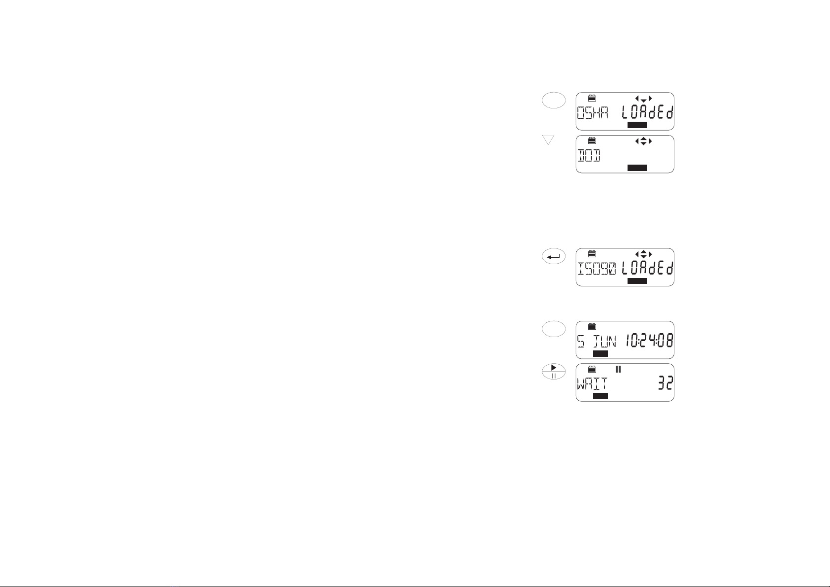
For countries that are subject to European Union regulations or
the equivelent ISO standards, these instruments measure the daily
sound exposure level (LAeq,8hr Pa2h according to IEC 1252, which is
identical with the LEX,8h required by ISO 1999), while for USA
OSHA/MSHA regulations they measure the Time Weighted Average
level (TWA).
When used as a sound level meter they display sound level,
maximum sound level, minimum sound level, peak, time-averaged (LAeq
or LAvg) sound levels and sound exposure level (SEL).
4.3 CEL-360/360S Logging Noise Dosimeters
In addition to the features available to the CEL-320 Dosimeters, the
following additional features apply to the CEL-360 and CEL-360S. These
instruments are recommended for detailed measurements as they
include extended processing and memory functions.
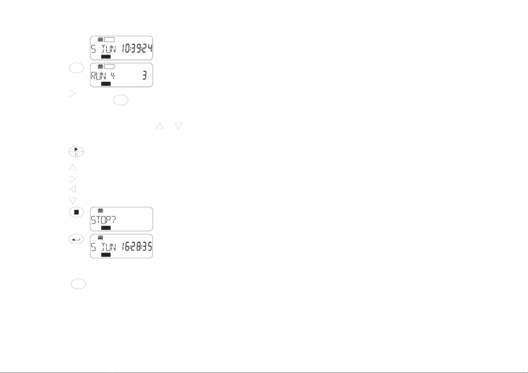
There are automatic run timing facilities controlled by the built-in
clock and time-history recording capabilities that allow up to 10 profiles
to be saved with each dose (DATA) result set, in a separate profile store.
Sampling times can be specified between 1 s and 1 hour by dB10 and
dB12 software, while profile storage is in excess of 220 000 data points,
where any single run can use up to 99 999 points.
The instruments are able to measure and save up to five user
specified Lnvalues (exceedance level percentiles). Run durations
specified via instrument keys, by dB10 or dB12, and start and stop times
preset via dB10 or dB12 can be switched on or off from the instrument
keys. Other settings can be changed only by dB10 and dB12 Software.
Table 2: Setups and Configuration Files
Parameter settings that do not modify preset
measurement protocols can be changed by using
the instrument keys.
All available parameter settings can be changed
from a PC by means of dB10 or dB12 Software.
Parameter settings that modify preset measure-
ment protocols must first be saved by dB10 or
dB12 under a new setup identity in an instrument
“configuration file”.
A“configuration file” contains a complete
instrument set of setups, i.e. seven fixed dose
setups, up to 13 user defined setups, one SLM
setup, and one timer setup common to all dose
setups.
Parameter settings on an instrument can be
changed ONLY by using dB10 or dB12 to replace
the configuration file in the instrument by another
configuration file loaded from the PC.
Page 6 - CEL-320/360 Getting Started

Once data saved by a CEL-360 instrument has been downloaded
to a PC, the user can specify a period over which to re-calculate the
projected % dose values. The software can also calculate six
exceedance time percentiles with levels preset to values specified by
measurement standards, plus one user specified time percentile.
5. Preparation for Use
5.1 Install Battery & Microphone
Connect a new 6LF22 or equivalent 9 V
battery to the terminals in the battery
compartment in the rear of the instrument.
DO NOT disconnect the battery
once runs have been stored as they
will be lost !
With the instrument switched
OFF, insert the lead connector of the
CEL-6681 Dosimeter Microphone or the
connector on the
CEL-425 SLM Adaptor
stalk into the socket
on the top end of the
case with the red dot
facing the front of the
dosimeter.
Remove the
connector ONLY by
pulling on the knurled
sleeve.
5.2 Perform Acoustic Calibration
Operations are controlled by a sequence of key strokes.
Perform a field accuracy check each time the instrument is
switched ON using a CEL-110/2 (Class 2) or CEL-110/1 (Class 1)
Calibrator as follows. It is also recommended that another acoustic
calibration be performed immediately after completing a measurement
run.
The calibration levels from both before and after are stored with
the run. When the second calibration occurs much later, provided the
same microphone assembly is used, the second level is attached to any
stored run that has no second calibration.
960079
SET
ENTER
MENU
DATA
STOP
01042e
CEL-6681
Dosimeter Microphon
e
CEL-425
SLM Adaptor
Knurled
Sleeve
Red "Dot"
CEL-320/360 Getting Started - Page 7

Fit the CEL-4726 Coupler
supplied with the calibrator (CEL-110/1 or
110/2 ) into the calibrator cavity, making
sure it is firmly in contact with the
shoulder in the cavity. (To aid removal,
the coupler flange does not fit close
against the calibrator housing).
Fit the microphone into the
coupler cavity, again ensuring that it
makes contact with the shoulder in the
coupler cavity.
Then follow these instructions.
Operation Press Display Shows Comments
1. Switch the
instrument
ON
Start Up messages show:
Instrument Type,
Serial Number (when set),
Print (when printer cable
connected),
Firmware Version,
finishing with the Last Used
Operating Mode.
2. Change
Operating
Mode re-
peatedly
To select OPTION, to enable
Acoustic Calibration, it shows
current SPL.
3. Enable
Level
Change
and are now enabled.
The display shows current
sound level.
4. Change
Indicated
Level
or Press or .
Indicated level rises (falls)
0.05 dB for each key press.
Adjust to correct level for
CEL-320/360 microphones at
standard temperature and
pressure: 114.0 dB.
5. Set
Calibration
Level
The 114.0 dB calibration level
is now set, and will be stored
in the microphone assembly.
6. If the
calibration is
to be aborted
The calibration level is
NOT SAVED and the
instrument continues to use
the last saved calibration.
DATA
MENU
OPTION
OPTION
OPTION
OPTION
OPTION
Calibrator
980057
1/4"
Microphone
'
O'Ring Should
er
Microphon
e
Coupler
Page 8 - CEL-320/360 Getting Started

6. Operation as a Dosimeter
6.1 Select Dose Setup for Use
Operation Press Display Shows Comments
1. Change
Operating
Mode re-
peatedly
To select SET UP.
The first display always shows
the currently loaded Setup, (for
example OSHA dose
measurement).
2. Select
another
Set Up several
times
Select required Set Up from
OSHA dose procedures,
MSHA dose procedures,
DOD dose procedures,
ACGIH dose procedures,
ISO85 dose procedures,
ISO90 dose procedures,
METER procedure,
SLM (see Section 7).
METER is a special procedure
with neither threshold nor
criterion, that allows the
instrument to store data as a
logging sound level meter.
3. Load Selected
Set Up for use
Loaded messages show the
Setup is now active (for
example ISO procedure with
90 dB Criterion).
6.2 Measure and Store Dose Data
Operation Press Display Shows Comments
1. Change
Operating
Mode re-
peatedly
This is dose measurement
where the display can show
dose data.
2. Start Run When the run TIMER of a
CEL-360 is ON (Section 8.3)
with Beginning and End times
set, the instrument waits
showing the pause icon and
the time remaining until the
run starts.
When the run TIMER of a
CEL-360 is ON (Section 8.3)
with SYNC ON, the instrument
waits until the clock is synchro-
nised with any selected profile
time before the run starts.
When the run Timer of a
CEL-360 is OFF (section 8.3),
or with a CEL-320, the instru-
ment waits until the next
whole clock second, then
starts the run.
MENU
SET UP
A
SET UP
A
SET UP
A
MENU
DATA
DATA
CEL-320/360 Getting Started - Page 9

Operation Press Display Shows Comments
3. Then REC icon indicates that the
instrument is now storing dose
data in the first available data
store.
4. Inspect data
from Current
Run
Shows where data from the
current run is being saved
(store 4) and on a CEL-360
indicates the number of
completed profile periods.
5. Inspect
further data
from Current
Run
several
times
Data from Current Run.
Pressing as for the
CEL-420/460 series will
also cycle the display.
The display cycles through
data from current run (see
Section 9.4).
Some of these displays offer
and options that show
further parameters.
The displays will be updated
while the run is in progress.
6. If Required Pause the run. The pause icon (II ) is shown.
Press this key again to resume
the run.
7. If Required
PLUS
To lock the keys and display
to prevent unauthorised
tampering.
The keys and display cannot
be locked while the instrument
is paused.
8. If Required
PLUS
To unlock the keys and
display to restore normal
operation.
9. Stop Run Stop ? This command must be
confirmed.
10. Confirm Stop The Run is now ended.
All stored runs will be
lost if the battery is
disconnected !
6.3. Recall Dose Data
Measured data stored while operating in the DATA mode can be
accessed via the key. Data from the run in progress can be
inspected while the instrument is recording, as described in Steps 4 and
5 of Section 6.2. When the instrument is stopped, with no data being
saved, stored data can be retrieved and displayed.
6.4 Review Stored Data
Stored data is identified by date and measurement start time. Up to 50
runs can be stored simultaneously before the memory is overwritten by
a “first-in/first-out” process.
DATA
REC
DATA
REC
DATA
DATA
DATA
DATA
DATA
Page 10 - CEL-320/360 Getting Started

Operation Press Display Shows Comments
1. Enable Data
Recall
With the instrument stopped,
pressing displays the
Start Date & Time for the most
recently stored run.
2. Review
Stored Runs repeat
Select Start Date & Time for
required run (for example
4 June 09:10:00).
3. Review
Stored Data
Shows where data from the
selected run is stored (store 3)
and on a CEL-360 indicates the
number of completed profile
periods.
4. Review
Stored data repeat
The display cycles through
data from the selected run
(see Section 9.4).
Pressing as for the
CEL-420/460 series will
also cycle the display.
Some of these displays offer
and options that show
further parameters.
If a printer is connected and
switched on, the second data
display shows PRINT READY
(see Section 6.5).
6.5 Print Standard Report
With the dosimeter switched OFF, use both the C6671 Cable (supplied
with all CEL-320/360 series instruments) and a CEL-6672 Cable to
connect the instrument to a Centronics printer as shown.
This
allows the
dosimeter to
recognise the
printer cable
during its Start
Up sequence.
Only
stored data can
be printed, as
the microphone and printer cannot be connected to the dosimeter at the
same time because they both use the same “Red Dot” connector.
Operation Press Display Shows Comments
1. Switch
instrument
ON
Switch on both dosimeter and
printer.
Switch the printer On-Line.
DATA
DATA
DATA
DATA
DATA
DATA
DATA
DATA
CEL-320/
CEL-360
Series
C6671
Communications
Cable
C6672 Active
Printer Cable
Centronics Printer
01040e
CEL-320/360 Getting Started - Page 11

Operation Press Display Shows Comments
2. Enable Data
Recall
With the instrument stopped,
display the Start Date & Time
for the most recently stored
run as described in Section 6.4.
3. Select Stored
Run For
Printing repeat
Select Start Date & Time for
required run (for example
4 June 09:10:00).
Continuing to press will
eventually offer PRINT READY,
followed by a PRINT ALL runs
option that is enabled by
pressing .
4. Review
Stored Data
Shows where data from the
selected run is stored (store 3)
and on a CEL-360 indicates the
number of completed profile
periods.
5. Activate
Printing
When the printer is connected
and switched on, the second
display shows PRINT READY.
If the printer is off, the display
will show PRINT OFF.
6. Print
Hard Copy
The display shows busy plus
print messages while printing
the data set from the selected
run in standardised format for
measurement protocol used.
7. Operation as a Sound Level Meter
In SLM mode, the instrument operates as a Type 2 sound level meter
using settings made via the keypad, however, this mode cannot store
data. For storage of sound level data, load the Meter setting from the
setup list (Section 6.1), then operate as a dose meter (Section 6.2).
Connect the CEL-425 SLM Adaptor (as described in Section 5.1),
perform an acoustic calibration as described in Section 5.2, then proceed
as follows.
Operation Press Display Shows Comments
1. Start from the
final Start Up
Display
The last used measurement
mode will be selected.
2. If required,
change Mode
Re-
peatedly
This is operation as a SLM
with the current A-weighted
Fast level (LAF) displayed.
SLM mode can be selected
only while a microphone is
fitted.
DATA
DATA
DATA
DATA
DATA
DATA
DATA
MENU
dB
SLM
A
Page 12 - CEL-320/360 Getting Started

Operation Press Display Shows Comments
3. Review
SLM
Measurements several
times
The display steps through all
details and parameters (see
Section 9.4), starting here with
Linear Peak (LLpk)
measurement.
When & icons are
shown on the display, the
relevant menu keys may be
used to change the current
measurement settings.
4. Final
Measurement
This completes the cycle back
to first SLM display.
5. Switch OFF Blank Screen No operations are possible.
8. Selecting & Changing Options
The OPTION mode accesses the part of the operating firmware that
allows the following items to be checked or adjusted.
Acoustic calibration (see Section 5.2),
Adjustment of the calendar clock and time,
Battery voltage, and Microphone temperature (oC),
Communication status when the instrument is connected to a
PC for use with dB10 or dB12 Soundtrack Software,
Activate/de-activate the Run Timer commands set by dB10 and
dB12 (only on a CEL-360 series).
8.1 Review Options
Operation Press Display Shows Comments
1. Start from the
Final Start Up
Display
2. Change Mode
several
times
Optional operations showing
SPL for acoustic calibration,
(see Section 5.2).
3. Next Option
Re-
peatedly
The display cycles through the
rest of the options:
Current Time,
Current Date,
Battery condition,
Communication status,
Timer status (CEL-360 series),
Microphone Temperature,
Erase: use this option with
caution - IT DELETES ALL
STORED DATA !
dB
SLM
SLM
A
DATA
MENU
OPTION
OPTION
CEL-320/360 Getting Started - Page 13

8.2 Set Time & Date
Operation Press Display Shows Comments
1. Select Time
Option
Follow on from Step 3 in
Section 8.1.
2. Enable Time
Change
Cursors are enabled and the
hours entry blinks to show it
can be edited.
3. Change the
entry or Use and to highlight
an entry.
Use and to change the
entry.
4. Save the
Changes
The new time setting is stored.
Repeat this process in the Date Option to set the date: PLEASE NOTE
that the date format is dd mm yy.
8.3 Change Timer & Run Duration (CEL-360 series)
Operation Press Display Shows Comments
1. Select Timer
Option
Follow on from Section 8.1.
Displays that are found only on
CEL-360 series instruments
are shown with a dashed
outline ----.
2. Switch Timer
ON
The Timer is now ON so that
any start and stop times
loaded via dB10 or dB12 will
be used, UNLESS
Synchronisation (SYNC) or
Duration (DUR) settings are
enabled as in steps 3 and 4.
3. Review Timer
settings
SYNC allows synchronisation
to the next profile boundary,
i.e to whatever interval has
been set by the PC software.
Press to enable or
disable.
The profile interval will also be
shown.
4. Review
Duration
setting
DUR allows the user to select
a run Duration time.
When a run duration period is
shown here or SYNC is ON,
these take precedence over
the Timer settings so that any
preset start and stop times
WILL NOT BE used.
OPTION
OPTION
OPTION
OPTION
OPTION
OPTION
OPTION
OPTION
Page 14 - CEL-320/360 Getting Started

Operation Press Display Shows Comments
Press to enable,
use and to select the
following durations:
Off, 5, 10, 15, 30 minutes,
1, 2, 4, 8, 10, 12, 24 hours,
then confirm with .
5. Review
Repeat
setting
Rept allows the user to select
up to 49 repeats of the timer
settings.
Press to enable,
use and to select the
number of repeats,
then confirm with .
6. Review Start/
End Times
This is the First Beginning
(start) time set by dB10 or
dB12: dd.hh:mm.
The day setting is the day of
the month. When day “- -” is
indicated, measurement will
start on the current day.
Press in either the Beg
or End screen to enable/
disable each timer pair.
When a pair is disabled, its
settings will be shown as “- - -
- - -”.
7. Review Start/
End Times
This is the First End (stop) time
set by dB10 (or dB12):
dd.hh:mm.
8. Review
further Start/
EndTimes Repeat
Start/End times. The display steps through 16
sets of Start/End times.
OPTION
OPTION
OPTION
CEL-320/360 Getting Started - Page 15

9. Technical Information
9.1 Specification
Dosimeter/Sound Exposure Meter Standards:
IEC 61252: BS EN 61252, ANSI S1.25 - 1992 for dosimeters and sound
exposure meters.
Electromagnetic and electrostatic compatibility:
The sound level at which this personal sound exposure meter conforms
to clause 15 of this standard is 85 dB. The personal sound exposure
meter was tested in Dose mode using 85 dB due to the duration of
testing.
The instrument has no additional connector points during normal mode
of operation.
N.B. When downloading data using cable no C6671, the meter
conforms to the requirements for EMC emissions and immunity as
specified in IEC 61000 - 61:1997, 61000 - 6 - 2:1999, 61000 - 6 - 3:1996,
and 61000 - 6 - 4: 1997.
The configuration for the normal mode of operation is measurement
set-up ISO 85 or ISO 90.
There is no degradation in performance or loss of functionality following
the application of electrostatic discharges.
The approved configuration for the reference orientation is with the
instrument secured to a nonmetallic backing material with the
microphone cable secured in a horizontal figure of eight configuration
starting approximately 10 cm above the instrument. The figure of eight
is constructed of four even folds of the microphone cable 14 cm across.
The figure of eight is then secured at each end and in the centre. The
microphone housing is then secured approximately 10 cm above the
centre of the figure of eight configuration. The front of the instrument is
facing the principal direction of an emitter or receiver of radio-frequency
electromagnetic fields.
All settings and orientations of the instrument have similar radio-
frequency emissions. These radio-frequency emissions are within the
specified limits of this standard.
All modes of operation and connecting device configurations have
similar immunity to power and radio frequency fields.
Sound Level Meter/Integrating Sound Level Meter Standards:
ANSI S1.4 - 1983 Type S(1) for sound level meters,
IEC 60651 - 1979 : Type 2Ifor impulse sound level meters,
IEC 60804 - 2000 : Type 2 for integrating sound level meters.
ANSI S1.43 - 1997 for integrating sound level meters.
The sound level at which the sound level meter conforms to
specifications of clause 12 of IEC 60651 is 74 dB.
The instrument has no additional connector points during normal mode
of operation.
The configuration for the normal mode of operation is specified with the
microphone connected via the standard preamplifier, Frequency
weighting: A-weighted, Sound Pressure level, Time Constant: Fast,
Measurement Range: 70 - 140 dB.
Page 16 - CEL-320/360 Getting Started

There is no degradation in performance or loss of functionality following
the application of electrostatic discharges.
The approved configuration for reference orientation as viewed by the
operator is with the instrument in a horizontal position facing the noise
source where the receiver of the electromagnetic field replaces the
noise source.
All settings and orientations of the instrument have similar radio-
frequency emissions. These radio-frequency emissions are within the
specified limits of this standard.
All modes of operation and connecting device configurations have
similar immunity to power and radio frequency fields.
Pulse Range:
>53 dB
Measurement Ranges:
Display Range (dB) Primary RMS range
at 1 kHz
Peak
30 - 100 41 - 86 63 - 103
50 - 120 55 - 106 83 - 123
70 - 140 75 - 125
Defined from 10 dB
above noise floor to a
crest factor limit of 5
103 - 143
Weightings:
Frequency: A, C and linear 20Hz - 20kHz,
Time: Fast, Slow, Impulse, Peak,
Amplitude: 3, 4, 5, 6 dB exchange rates.
Clock:
Date and time can be set from the keypad.
Date and time can be set to PC time via dB10 and dB12.
Dose Measurement Timer: (CEL-360 Series only)
Use with pre-programmed delayed start and stop times, or with fixed
measurement durations can be selected from the keypad.
(Start and Stop times must be programmed via dB10 and dB12.)
Dose Measurement Start/Stop Delay Timer: (CEL-360 Series only)
Delay intervals can be set only via dB10 and dB12.
Settings can be specified for up to 16 sets of start and stop times, up to
30 days ahead.
The clock indicates the time remaining before the next run starts.
Dose Measurement Elapsed Time Timer: (CEL-360 Series only)
Measurement elapsed times (run durations) can be selected from the
keypad. The following options are available:
Disabled,
5, 10, 15, 30 minutes,
1, 2, 4, 8, 10, 12, 24 hours.
Under Range Indication:
1 dB below the bottom of the selected range.
CEL-320/360 Getting Started - Page 17

Overload Indication:
140.1 dB RMS (i.e. 0.1 dB above the top of the selected range).
Maximum Peak Value:
143.0 dB Peak Linear (i.e. 3.0 dB above the top of the selected range).
Non-Linear Distortion:
Error <±1 dB at frequencies >10 Hz.
Stabilisation Time:
1 second.
Operating Environment:
Temperature ± 0.5 dB: -10oC to +50oC,
Atmospheric Pressure: 65 - 108 kPa,
Humidity ± 0.5 dB: 30% - 90% (non-condensing),
Magnetic Fields: Negligible,
Vibration: Negligible.
Battery:
9 V, 6LF22 or equivalent for normal use, lifetime at least 35 Hours.
I.S. Models have a minimum battery life of 30 hours.
Dimensions and Weight:
120 x 65 x 30 mm, 280 g (IS Models 380 g)
4.8 x 2.6 x 1.2 inches, 9 oz (IS Models 120 oz)
9.2 CE Compliance
All models in the CEL-320/360 Series comply with the EMC Directive
89/336/EEC of the European Union. They have been tested according to
the standard delivery schedule and comply with the following standards.
EN 50081-1 : 1992, EN 50081-2 : 1993: Generic emission
standards for residential, commercial, light industry and industrial
environments.
EN 50082-1 : 1992, EN 50082-2 : 1995: Generic immunity
standards (for both RF fields and electrostatic discharge) for residential,
commercial, light industry and industrial environments.
9.3 Default Parameter Settings
Setup OSHA MSHA DOD ACGIH IS085 IS090 METER SLM
Measurement70 - 140 70 - 140 70 - 140 70 - 140 70 - 140 70 - 140 50 - 120 70 - 140
range (dB)
Frequency A A A A A A A A
weighting
Time weighting SSSSFFFS
Amplitude 55433333
weighting
Peak frequency LLLLCCCL
weighting
Threshold 1 80 80 80 80 70 70 0 x
(dB)
Page 18 - CEL-320/360 Getting Started

Setup OSHA MSHA DOD ACGIH IS085 IS090 METER SLM
Threshold 2 90 90 x x x x x x
(dB)
Criterion (dB) 90 90 85 85 85 90 0 x
LN%A L10 L10 L10 L10 L10 L10 L10 x
LN%B L50 L50 L50 L50 L50 L50 L50 x
LN%C L90 L90 L90 L90 L90 L90 L90 x
LN%D L95 L95 L95 L95 L95 L95 L95 x
LN%E L99 L99 L99 L99 L99 L99 L99 x
Profile interval 1 min 1 min 1 min 1 min 1 min 1 min 1 min x
Profile 1 Lavg Lavg Lavg Lmn Leq Leq Leq x
Profile 2 Leq Leq Leq Leq Lmx Lmx Lmx x
Profile 3 Lmx Lmx Lmx Lmx Lmn Lmn Lmn x
Profile 4 Lpk Lpk Lpk Lpk Lpk Lpk Lpk x
Synchronise
Run start in Yes Yes Yes Yes Yes Yes Yes No
CEL-360 model
Allow user to No No No No No No Yes Yes
change set up
Reference 29 CFR 30 CFR 62.0 DoD DHHS Pub Noise at Noise at CEL CEL
document 1910.95 UMHRPEL Instruction 98-126 Work Work suggestion suggestion
6055.12 Regulations Regulations
1989 1989
9.4 Parameter Identities
The following time weightings and other identities may be shown.
A A-weighting
C C-weighting
L Linear
S Slow,
F Fast,
IImpulse,
Q Energy conversion factor
PK Peak,
MX Maximum,
MN Minimum,
EQ Equivalent continuous level,
AV Average level,
EP,v* Noise dose normalised to a user selected
(variable) period of hours and minutes,
When the period is set to 8 hours, this will be
shown a EP,d.
TWAv* Time Weighted Average is the normalised time
averaged sound pressure level with the selected
frequency and time weighting that represents
Note*: This parameter can be enabled only via the dB10 or dB12 PC software.
CEL-320/360 Getting Started - Page 19

the total Avg of a person’s workplace noise
exposure averaged over a user selected
(variable) period of hours and minutes.
This unit is specified in the USA: OSHA standard
1910-95 published in 1983.
When the period is set to 8 hours, the unit will
be shown as TWA.
N Percentile sound level,
AE Sound exposure level.
10. Parts, Servicing & Warranty
10.1 Schedule of Parts
A complete Noise Dosimeter or Sound Level Meter consists of:
CEL-320/360 Noise Dosimeter as applicable (/IS if IS model),
Either: CEL-6681(or CEL-6681/IS ifI.S.instrument),
Type 2, ¼" Electret Microphone Assembly for
use as a dosimeter, complete with clip and 0.8
m captive cable,
Or: CEL-425 Sound Level Meter Adaptor with Type 2, ¼"
Electret Microphone Assembly for use as a
sound level meter, (or CEL-425/IS if I.S.
instrument)
CEL-6702 dB10 Control and Download software (supplied
with CEL-320),
CEL-6704 dB12 Control, Download and Graphing software
(supplied with CEL-360),
C6671 Communication cable to PC,
016014 Alkaline-Manganese Battery (IEC 9LF22),
060333 Users Guide, A5 multilingual instructions,
060335 Field Guide, pocket guide.
10.2 Servicing & Warranty Arrangements
To ensure its conformity with the specification, this instrument is
thoroughly inspected and it’s accuracy verified prior to dispatch. All
technical information is filed under the instrument serial number, which
should, therefore, be quoted in any correspondence.
The manufacturers undertake to rectify any defect in the
instrument that is directly attributable to faulty design or assembly, and
which becomes apparent during the warranty period. In order to take
advantage of this warranty, the instrument must be returned, carriage
paid, to the manufacturer’s factory or accredited agent, where necessary
repairs will be carried out.
Page 20 - CEL-320/360 Getting Started
This manual suits for next models
1
Table of contents
Other Casella Measuring Instrument manuals

Casella
Casella CEL-350 dBadge User manual

Casella
Casella DBADGE2PRO User manual

Casella
Casella HB4056-01 dBadge2 User manual

Casella
Casella CEL-350 dBadge User manual

Casella
Casella CEL-960 User manual

Casella
Casella CEL-240 User manual

Casella
Casella HB4087-01 User manual

Casella
Casella CEL-490 Service manual

Casella
Casella Evolution CM2010 User manual

Casella
Casella STORM Guardian Service manual