CASPR TRANSIT 120V User manual

Owner’s Manual
CAUTION: Read manual carefully for proper procedures and operation.
TRANSIT
Air & Surface Disinfection

2
Congratulations
on your purchase of a CASPR Technologies enhanced air and surface disinfection
system. This unit is designed to be mounted into any vehicle. Please read and
follow all safety warnings and service procedures outlined in this manual. Use
only genuine CASPR Technologies replacement parts available from your CASPR
Technologies Distributor.
If you have any questions concerning this or any CASPR Technologies product,
contact your CASPR Technologies Distributor.
Principles of Operation
CASPR Transit uses Natural Catalytic Conversion (NCC) to generate safe, low
levels of hydrogen peroxide. NCC technology replicates natural purifying processes
by using a high intensity light to activate a proprietary metal catalytic coating,
converting water vapor into hydrogen peroxide. Hydrogen peroxide acts as
an oxidizer inactivating surface and air pathogens. It can compromise cellular
integrity by disrupting cell walls, or internal molecular structures, rendering
contaminants harmless.
To learn more about the CASPR Transit and other CASPR Technologies products
and technologies, please visit our website at www.casprtech.com.
Table of Contents
Warnings ................................................................................................... 3
Specications.............................................................................................. 3
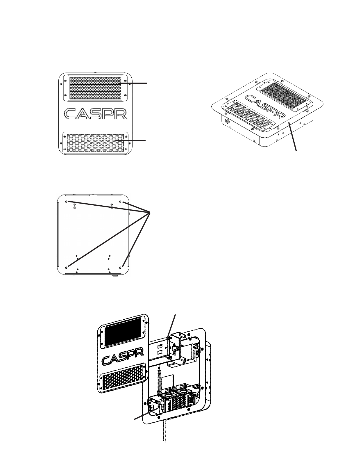
Unit Diagrams............................................................................................. 4
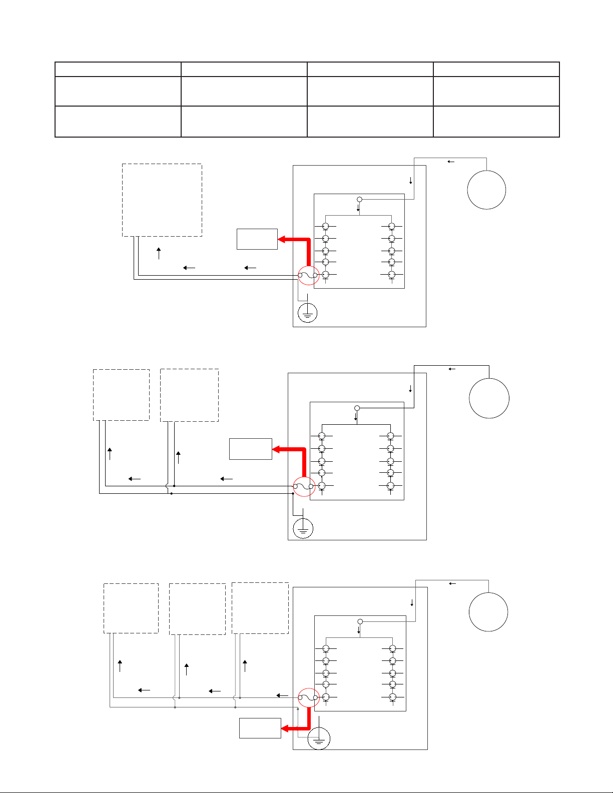
Installation ................................................................................................. 5
Filter Cleaning and Replacement.................................................................... 7
Cleaning the Unit......................................................................................... 8
NCC Cell Replacement.................................................................................. 8
Fuse Replacement ..................................................................................... 10
Cell Disposal ............................................................................................. 11
Troubleshooting......................................................................................... 11
Replacement parts (purchased separately): .................................................. 11
Warranty Information................................................................................. 12

3
TRANSIT 120V TRANSIT 24V TRANSIT 12V
Weight 4.0 lbs 4.0 lbs 4.0 lbs
Dimensions
(WxLxH)
9” x 10” x 2.6”
11” x 12” x 2.6” (ush mount)
9” x 10” x 2.6”
11” x 12” x 2.6” (ush mount)
9” x 10” x 2.6”
11” x 12” x 2.6” (ush mount)
Electrical Input
100-240VAC 50/60Hz 1.8A
277VAC 50/60Hz 0.9A
(277VAC - North America only)
19-36VDC 1.5A 9-36VDC 1.5A
Amp. Draw AC 0.02A DC 0.57A DC 0.65A
Air ow (CFM) 17.9 17.9 17.9
Noise (dBA) 48 48 48
Min/Max
Operating Temp 14°- 140°F 14°- 140°F 14°- 140°F
IMPORTANT SAFETY INSTRUCTIONS
When using an electrical appliance, basic precautions should always be taken.
READ ALL INSTRUCTIONS BEFORE USING THIS PRODUCT
WARNING!
To reduce the risk of re, electrical shock, or injury:
• Use only as described in this manual.
• Do not attempt to repair or adjust any of the electrical or mechanical functions.
Contact Customer Service for service information.
• Do not use outdoors or on wet surfaces.
• Do not allow to be used as a toy. Do not allow children around the unit.
• Do not handle appliance with wet hands.
• Do not allow foreign objects to enter the ventilation openings.
• Keep hair, clothing, ngers, and all parts of body away from openings.
• Do not touch NCC bulb with bare hands.
WARNING
WARNING! - UV light in operation. Disconnect unit from
power supply before servicing. Failure to follow warnings
may result in severe eye damage.
Specications

4
Unit Diagrams
Unit Front
Air Outlet
Filter
Unit Back
Security
Mounting Holes
Unit Internals
Flush Mounting Bracket
Fuse
NCC Cell

5
Installation
Before installation, identify wiring routes in order to select the most optimal
location for this install.
All electrical wiring should be done by a licensed technician or mechanic
that has experience locating and wiring low voltage.
Flush Mount Installation
1. Cut hole where the unit will be inset into the
wall. Unit is 9” x 10” x 2.6”.
2. Unscrew the bracket from the main unit. Then
move the bracket from the bottom of the unit
and screw it back on the top of the unit so the
bracket is now ush with the top lid as seen in
the image.
3. Place unit into the cut hole.
4. Use the 8 self-tapping screws to attach the
unit to the surface.
5. Connect wiring into the 24VAC or the 12VAC power source. Refer to wiring
guidelines below.
Surface Mount Installation
1. Identify where the unit will be placed / Drill hole for wire (If needed)
2. Attach the unit ush to the surface of the vehicle by using 8 screws to secure
the unit in place. Connect wiring into the 24VAC or 12 VAC power sources.
Refer to wiring guidelines below.
Wiring Guidelines
• WHEN INSTALLING ON A BUS, PAY SPECIAL ATTENTION TO FEDERAL,
STATE, AND LOCAL CODES. WHEN APPLICABLE, THE SYSTEM MUST BE
WIRED THROUGH THE SAFETY NOISE SUPPRESSION RELAY SYSTEM.
• Wire the system through a relay system to prevent the CASPR unit/s
from draining the battery when not in operation.
• A fuse must be installed at the source of the power supply when
installing a CASPR Transit unit onto a vehicle. Always use fuses specic
to your vehicle’s specications. Use the fuses table below to install the
appropriate fuse.
• Vehicles are subject to vibration; when running wire throughout the vehicle, be
sure to include slack in all wiring.
• 18 gauge stranded wire should always be used.

6
12V/24V
CASPR Transit
PROPRIETARY AND CONFIDENTIAL: THE INFORMATION
CONTAINED IN THIS DRAWING IS THE SOLE PROPERTY OF
CASPR Group Inc. ANY REPRODUCTION IN PART OR AS A
WHOLE WITHOUT THE WRITTEN PERMISION OF CASPR
Group Inc. IS PROHIBITED.
DRAWN B.Taylor Wiring Diagram CASPR Transit
ENGINEER B.Taylor DRAWING NO.
CHECKED J.Nixson 6 Dec. 2021
12V/24V
Using the available power source please be sure to
include an in-line fuse.
PLEASE ADVISE FAILURE OF USING A FUSE AT
THE POWER SOURCE COULD INCREASE THE
CHANCES OF A THERMAL EVENT
* For more information in regards to fuses please
See section (Insert Section)
16/2 Gauge wire
White: +
Black: -
Positive
Charge
from
Battery
+-
ATM or ATC
Fuse
12V/24V
CASPR Transit
PROPRIETARY AND CONFIDENTIAL: THE INFORMATION
CONTAINED IN THIS DRAWING IS THE SOLE PROPERTY OF
CASPR Group Inc. ANY REPRODUCTION IN PART OR AS A
WHOLE WITHOUT THE WRITTEN PERMISION OF CASPR
Group Inc. IS PROHIBITED.
DRAWN B.Taylor Wiring Diagram CASPR Transit
ENGINEER B.Taylor DRAWING NO.
CHECKED 6 Dec. 2021
12V/24V
Using the available power source please be sure to
include an in-line fuse.
PLEASE ADVISE FAILURE OF USING A IN-LINE
FUSE COULD INCREASE THE CHANCES OF A
THERMAL EVENT
* For more information in regards to fuses please
See section (Insert Section)
16/2 Gauge
wire
White: +
Black: -
Positive
Charge
from
Battery
+
-
12V/24V
CASPR Transit
+
-
16/2 Gauge
wire
White: +
Black: -
ATM or ATC
Fuse
12V/24V
CASPR Transit
PROPRIETARY AND CONFIDENTIAL: THE INFORMATION
CONTAINED IN THIS DRAWING IS THE SOLE PROPERTY OF
CASPR Group Inc. ANY REPRODUCTION IN PART OR AS A
WHOLE WITHOUT THE WRITTEN PERMISION OF CASPR
Group Inc. IS PROHIBITED.
DRAWN B.Taylor Wiring Diagram CASPR Transit
ENGINEER B.Taylor DRAWING NO.
CHECKED 6 Dec. 2021
12V/24V
Using the available power source please be sure to
include an in-line fuse.
PLEASE ADVISE FAILURE OF USING A IN-LINE
FUSE COULD INCREASE THE CHANCES OF A
THERMAL EVENT
* For more information in regards to fuses please
See section (Insert Section)
16/2 Gauge
wire
White: +
Black: -
Positive
Charge
from
Battery
+-
12V/24V
CASPR Transit
+
-
16/2 Gauge
wire
White: +
Black: -
ATM or ATC
Fuse
12V/24V
CASPR Transit
+
16/2 Gauge
wire
White: +
Black: -
-
J. Nixson
1 Unit
2 Units Wired in Parallel
3 Units Wired in Parallel
ATTENTION: FAILURE TO USE AN IN-LINE FUSE CAN INCREASE THE CHANCES OF A THERMAL
EVENT. WIRE THROUGH A RELAY SYSTEM TO PREVENT THE BATTERY FROM DRAINING.
1818
1818 1818
1818 1818 1818
ATTENTION: FAILURE TO USE AN IN-LINE FUSE CAN INCREASE THE CHANCES OF A THERMAL
EVENT. WIRE THROUGH A RELAY SYSTEM TO PREVENT THE BATTERY FROM DRAINING.
ATTENTION: FAILURE TO USE AN IN-LINE FUSE CAN INCREASE THE CHANCES OF A THERMAL
EVENT. WIRE THROUGH A RELAY SYSTEM TO PREVENT THE BATTERY FROM DRAINING.
Fuses
Unit 1 Unit 2 Units Wired in Parallel 3 Units Wired in Parallel
TRANSIT 12V 3 Amps 6 Amps 9 Amps
TRANSIT 24V 3 Amps 6 Amps 9 Amps

7
Filter Cleaning and Replacement
We recommend cleaning the lter every 90 days, or when noticeably
contaminated, by vacuuming the lter through the front lter cover. The lter
should be replaced every 6 months. Service should only be performed by a
qualied technician.
WARNING: Never service the unit while it is connected to a power source.
Electrical shock or injury may occur. Make sure the power switch is turned
OFF and the unit is unplugged prior to handling.
1. Disconnect unit from power source.
2. Remove the front cover from the unit by unscrewing the four Phillips head
captive screws.
Filter
3. Remove the used lter by pinching the lter material and sliding it out of the
bracket on the back side of the front cover.
4. Replace with the new lter.
5. Reattach the front cover.
6. Reconnect unit to power source.
NOTE: The lter may alternatively be replaced via the front lter cover using a T-8
tamper-proof torx bit.

8
Cleaning the Unit
The unit will need to be cleaned occasionally, We recommend wiping it down each
time you replace or clean the lter.
WARNING: Never service the unit while it is connected to a power source.
Electrical shock or injury may occur. Make sure the power switch is turned
OFF and the unit is unplugged prior to handling.
1. Disconnect unit from power source.
2. Remove the front cover from the unit.
3. Wipe all internals, other than the NCC cell and bulb, down with a damp cloth
(Fan, ballast, covers, etc).
4. Reattach the front cover of the unit.
5. Reconnect unit to power source.
NCC Cell Replacement
Your CASPR Transit unit requires replacement of the NCC cells and bulbs every 18-
24 months, even if the bulb appears to be operating normally.
Service should only be performed by a qualied HVAC technician. Make sure there
is no power going to the unit prior to handling.
WARNING: Never service the unit while it is connected to a power source.
Electrical shock or injury may occur.
WARNING: Please do not throw a used NCC Cell in the garbage. See “Cell
Disposal” on page 8 for more information.
1. Disconnect unit from power source.
2. Remove the Front Cover from the unit by unscrewing the four phillips head
captive screws.

9
3. Unscrew the mounting bracket
assembly holding the NCC Cell in
place and lift it up out of the case.
4. Unscrewing the two screws located
on the sides of the cell housing.
5. Separate the Cell housing from the
mounting bracket
6. Disconnect the bulb.
Dispose of the used bulb appropriately. Do NOT throw it in the trash. See “Cell
Disposal” on page 8 for more information.
7. Remove the new Cell Assembly from the packaging box.
8. Carefully remove the new bulb from new cell housing.
DO NOT touch the bulb with bare hands.
9. Before replacing the new cell assembly into the transit, you must rst remove
the support bracket that came with the replacement cell. Detach the metal
bracket on the end of the new replacement cell housing by unscrewing the two
screws located on the sides. You will no longer need the support bracket from
the new replacement cell once it has been removed.

10
10. Connect the new
Bulb to socket
in the mounting
Bracket Assembly.
11. Attach the new
Cell Housing to the
mounting bracket
with the previously
removed screws (2).
12. Install the Assembly
onto the TRANSIT unit
and secure with the
two thumb screws.
13. Reattach the Cover.
14. Reconnect unit to power source.
Fuse Replacement
If you nd the unit is powered off, even after activating the interlock switch and
changing the bulb, you may need to replace the internal fuse. This can be done
using the instructions that follow. If this still does not work, remember to check
any in-line fuses that may have been added during install (page 6).
1. Disconnect unit from power source.
2. Remove the Front Cover from the unit by unscrewing the four phillips head
captive screws and locate the fuse.

11
3. Unscrew the two plastic pieces folding the fuse in place.
4. Replace the fuse with a new 3amp 250 VAC 5mm x 20mm fuse.
5. Screw the two plastic fuse covers together to complete the circuit.
6. Reattach the Cover.
Cell Disposal
Do not throw a used NCC Cell in the garbage. The special germicidal UVC bulb
used in the unit contains a very small amount of mercury. Dispose of the spent
NCC Cell and UV Lamp at your local recycling center or by local regulations. To
learn more, visit www.lamprecycle.org.
Troubleshooting
If your NCC Cell or CASPR TRANSIT fan does not turn on, check to ensure a
secure connection. If secure, but the fan is not on, it may need to be replaced.
If the connection is secure but the cell does not light up, the NCC cell or ballast
may need to be replaced. When conducting maintenance ensure that the cover
is properly installed so that the interlock switch is activated. If still, an issue
persists, try replacing the 3 amp internal fuse using the instructions described
above. If none of the prescribed steps work, please contact your CASPR authorized
distributor with your serial number.
Replacement parts (purchased separately):
NCC Cell (Ozone-Free) Item #CELL-HV-5-001-AP-TR
Filter Item #CA450769011
Fuse Item # CA450756-3

12
LIMITED 3 YEAR WARRANTY ON CASPR Technologies
UNITS AND 1 YEAR WARRANTY ON CASPR Technologies
REPLACEMENT PARTS
Customer should not repackage and ship the CASPR
Transit unit due to possibility of irreparable damage.
For warranty service, please contact your CASPR
Technologies Distributor for the address of the nearest
Customer Service at 844-717-8819.
WHAT IS COVERED BY THIS WARRANTY
We warrant the CASPR Transit to the Customer, subject
to the conditions below, against defects in workmanship
or material, provided that the products are returned to a
service location within three (3) years from the date of
purchase.
INSTALLATION AND MAINTENANCE REQUIREMENTS
This warranty is expressly conditioned upon proper
installation, operation, cleaning and maintenance,
all in accordance with the Owner’s Manual. Failure to
meet any of these requirements will void this warranty.
Servicing of your CASPR Transit by parties other than our
authorized representatives and/or using parts other than
genuine parts will also void this warranty.
HOW TO OBTAIN WARRANTY SERVICE
Customer must contact their CASPR Technologies
Distributor and provide proof of purchase within the
above time periods. We will repair or replace and return
the product, without charge and within a reasonable
period of time, subject to the conditions herein, if its
examination shall disclose any part to be defective in
workmanship or material. If we, in our discretion, are
unable to repair the product after a reasonable number
of attempts, we will provide either a refund of the
purchase price or a replacement unit, at the company’s
option.
WHAT IS NOT COVERED BY THIS WARRANTY
Ordinary wear and tear shall not be considered a defect
in workman- ship or material. These warranties do
not apply to lters nor for loss or damage caused by
accident, re, abuse, misuse, improper installation,
leaking, modication, misapplication, or by any repairs
other than those provided by our authorized Service
Center. This warranty is non-transferable.
MISSING SERIAL NUMBERS AND UNAUTHORIZED
CHANNELS
If a valid serial number is missing from the product, the
warranty will be voided. CASPR Technologies products
are authorized for sale through CASPR Technologies
Distributors only. Warranties are voided if a product
is purchased through unauthorized channels; this
includes websites that are not authorized to use CASPR
Technologies’s trademarked names, images and logos as
well as Internet auction sites (e.g. eBay and craigslist).
To conrm warranty coverage prior to purchasing a
product, contact CASPR Technologies at 844-717-8819
with the serial number located on the back of the unit.
EXCLUSION OF OTHER WARRANTIES AND
CONDITIONS EXCEPT AS PROVIDED HEREIN, WE
MAKE NO REPRESENTATION OR WARRANTY OF
ANY KIND. ALL OTHER WARRANTIES OF ANY KIND,
EXPRESS OR IMPLIED, ARE HEREBY EXPRESSLY
DISCLAIMED, INCLUDING ANY IMPLIED WARRANTY OF
MERCHANTABILITY OR FITNESS FOR A PARTICULAR
PURPOSE.
LIMITATION OF LIABILITY FOR SPECIAL, INCIDENTAL,
OR CONSEQUENTIAL DAMAGES
WE SHALL NOT IN ANY CASE BE LIABLE FOR
SPECIAL, INCIDENTAL OR CONSEQUENTIAL
DAMAGES ARISING FROM BREACH OF EXPRESSED OR
IMPLIED WARRANTIES, CONDITIONS, GUARANTEES
OR REPRESENTATIONS, BREACH OF CONTRACT,
NEGLIGENCE OR ANY OTHER LEGAL THEORY. Such
excluded damages include, but are not limited to, loss of
prots or revenue, and loss of the use of the products,
and any loss caused by leaks or other water damage.
FOR U.S. APPLICATION ONLY
This warranty gives you specic legal rights, and you
may also have other rights which vary from state
to state. Some states do not allow limitations on
warranties, or on remedies for breach. In such states,
the above limitations may not apply to you.
FOR CANADIAN APPLICATION ONLY
Exclusion of Subsequent Owners: Except as otherwise
required by applicable legislation, this warranty is not
transferable. This warranty gives you specic legal rights
and you may also have other rights which vary from
province to province. Some provinces and territories
do not allow limitations on warranties, or on remedies
for breach. In such provinces or territories, the above
limitations may not apply to you. If any provision of this
warranty or part thereof is held by a court of competent
jurisdiction to be invalid, illegal, or unenforceable, the
validity, legality and enforceability of the remaining
provisions or parts thereof will not in any way be
affected or impaired within the jurisdiction of that
court. This entire warranty shall continue to be valid,
legal and enforceable in any jurisdiction where a similar
determination has not been made.
This warranty is provided by:
CASPR Technologies, Inc.
4505 Excel Parkway, #600
Addison, TX 75001
SERVICE
Every effort is made to ensure customers receive
an up-to-date instructions manual on the use of our
products; however, from time to time, modications to
our products may without notice make the information
contained herein subject to alteration. For the latest
information, please visit our website.
Warranty Information

13
www.CASPRTech.com
4505 Excel Pkwy Suite 600,
Addison, TX 75001
(844) 717-8819
V. IN-M-TR-01-11062021-AE
Other manuals for TRANSIT 120V
1
This manual suits for next models
2
Table of contents
Other CASPR Cleaning Equipment manuals
Popular Cleaning Equipment manuals by other brands

Kwunphi
Kwunphi Kwun-E11L manual

Tregaskiss
Tregaskiss TOUGH GUN TT Series Technical guide

Cleantecs
Cleantecs SOLA-TECS W BJ 2010 Series operating instructions

Streamline
Streamline STREAMFLO MINI instruction manual

Kärcher
Kärcher Chariot CV 60/1 RS KIRA Autonomous manual

HydraMaster
HydraMaster Boxxer 318 owner's manual