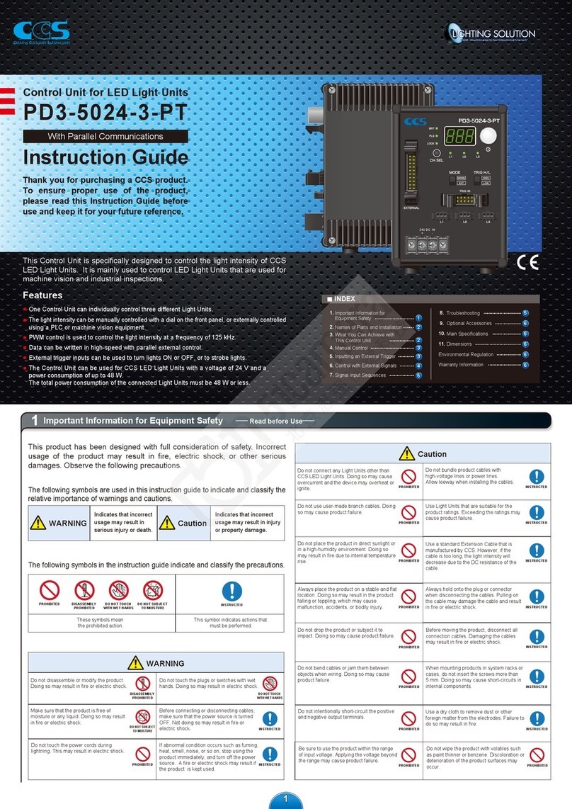
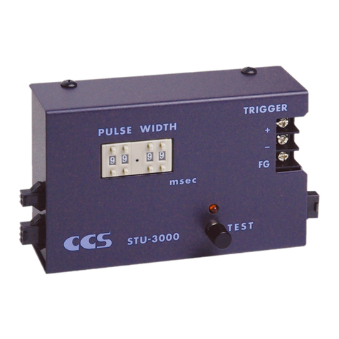
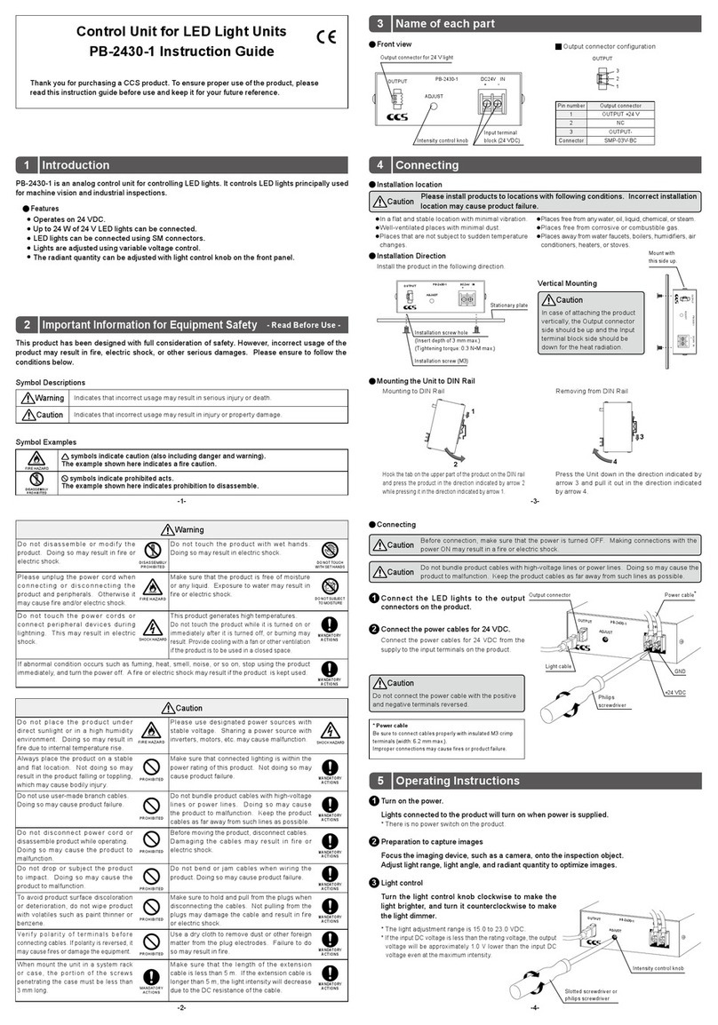
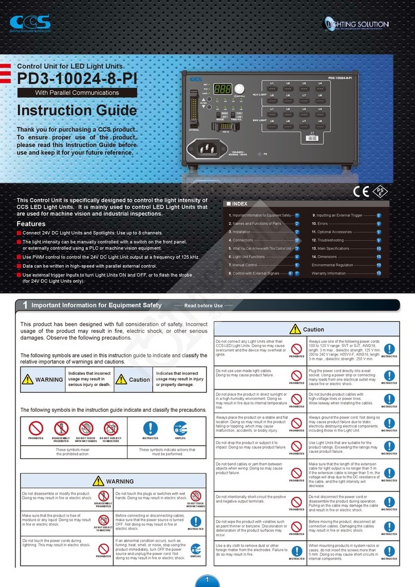
manuals.online logo
Brands
  1. Home
  2. •
  3. Brands
  4. •
  5. CCS
  6. •
  7. Control Unit
  8. •
  9. CCS PJ Series Manual

CCS PJ Series Manual

Using Models with an AC Input
Name and Function of Each Part
1
Wire Connection
3
Do not bundle the cables with high-voltage lines or power lines. Doing so may cause the
Control Unit to malfunction. Keep the cables as far away from such lines as possible.
Caution
Make sure that the power source is turned OFF, and then connect the Control Unit.
Making connections while the power source is turning ON may result in a re or electric shock.
Warning
Connect the Spot Light to the Control
Unit output connector.
Ground the FG terminal.
(Ground the FG terminal if the ground wire in
the power cord is not grounded.)
Use a wire of approximately 0.5 to 1.25 mm2
(AWG20 to AWG16) for the FG terminal.
Connect power cord to the AC inlet
and wall socket.
Connect the external control cable if
you perform the external control.
1
2
4
FG
Remote control
100-240V~
50/60Hz 27VA
Output
Spot Light
1
4
External control cable
2FG cable
3Power cord
3
Installation
2
・振動が少 な い 、水 平 で 安 定 し ている。
・埃 が 少 な い 、換 気 の よ い 。
・水、油、液、薬品、蒸気などが本製品にかからない。
・腐食性ガスや可燃性ガスがない。
・水道、湯沸かし器、加湿器、クーラー、ヒーター、
ストーブなどが近くにない。
・温度が急に変化しない。
・必ず接地できる。
※並べて設置する際は上方50mm以 上 、左 右
20mm以 上 の 間 隔 を あ け て 設 置 してく ださい 。
底面固定
Coarse
Fine
L1 L2
Power
1
2
3
4
5
67891011
12
13
14
15
16
1
2
3
4
5
67891011
12
13
14
15
16
1
2
3
4
5
67891011
12
13
14
15
16
1
2
3
4
5
67891011
12
13
14
15
16
ゴム足をはずして固定します。
※下図に示す方向以外では固定しないでください。
固定方法
本製品と接続するケーブル類は高圧線や動力線と束ねると誤動作の原因となり
ます。できるだ け 離して 配 線 してください 。
配 線 に あたっての 注 意
設置場所
4設置のしかた
Coarse
Fine
L1 L2
Power
1
2
3
4
5
67891011
12
13
14
15
16
1
2
3
4
5
67891011
12
13
14
15
16
1
2
3
4
5
67891011
12
13
14
15
16
1
2
3
4
5
67891011
12
13
14
15
16
50mm
20mm
縦置き
Coarse
Fine
L1 L2
Power
1
2
3
4
5
67891011
12
13
14
15
16
1
2
3
4
5
67891011
12
13
14
15
16
1
2
3
4
5
67891011
12
13
14
15
16
1
2
3
4
5
67891011
12
13
14
15
16
20mm
50mm
横置き
拡大図
固 定ネジ 穴
固定ネジ (M3)
(挿入深さ 5mm 以下 )
(締 付けトル ク 0.3N
・
m以下 )
ゴム足固定穴
これを 引き 抜くと
ゴム足が取れます
ゴム足
側面固定
Coarse
Fine
L1 L2
Power
1
2
3
4
5
67891011
12
13
14
15
16
1
2
3
4
5
67891011
12
13
14
15
16
1
2
3
4
5
67891011
12
13
14
15
16
1
2
3
4
5
67891011
12
13
14
15
16
横置き
この 面 を上にして 固 定
本体: 背面
固 定ネジ 穴
縦置き
固定板
(板厚 1.6t 以上 )
On/Off
100-240V~
1
2
L1
Light
L2
L1
(FAN)
EXT
GND
固定ネジ (M3)
(挿入深さ 5mm 以下 )
(締 付けトル ク 0.3N
・
m以下 )
以下の条件のところに設置してください。
設 置 場 所 に よっては 製 品 が 故 障 する恐 れ がありま す。
(P22 図面掲載)
注意
注意
Coarse
Fine
L1 L2
Power
1
2
3
4
5
67891011
12
13
14
15
16
1
2
3
4
5
67891011
12
13
14
15
16
1
2
3
4
5
67891011
12
13
14
15
16
1
2
3
4
5
67891011
12
13
14
15
16
ゴム足をはずして固定します。
拡大図
固 定ネジ 穴
固定ネジ (M3)
(挿入深さ 5mm 以下 )
(締 付けトル ク 0.3N
・
m以下 )
ゴム足固定穴
これを 引き 抜 くと
ゴム足が取れます
ゴム足
5
010
5
010
1
2
3467
8
91
2
346
9
7
8
L2
Control
Range
Remote
Hi
Lo Manual
Intensity
Power
L1
PJ-1505-2CA
Hi
5
010
5
010
1
2
3
46
7
8
91
3
46
9
7
8
L2
ControlRange Remote
Lo Manual
Intensit y
Power
L1
PJ-1505-2CA
2
Hi
5
010
5
010
1
2
3
46
7
8
91
3
46
9
7
8
L2
ControlRange Remote
Lo Manual
Intensit y
Power
L1
PJ-1505-2CA
2
5
5
3
46
73
46
Hi
0100 10
1
28
919
7
8
L2
Control
Range Remote
Lo Manual
Intensity
Power
L1
PJ-1505-2CA
2
Rubber foot
Rubber foot hole
Remove the screw.
Installation screw hole
Installation screw (M3)
Remove all of the rubber feet.
Insert M3 screws*into the installation screw
holes and secure them.
1
2
Securing the Bottom
In a at and stable location with minimal vibration.
Well-ventilated places with minimal dust.
Places that are not subject to sudden temperature
changes.
Places free from any water, oil, liquid, chemical or steam.
Places free from corrosive or combustible gas.
Places away from water faucets, boilers, humidiers, air
conditioners, heaters or stoves.
Please install the Control Unit in locations with following conditions.
Incorrect installation location may cause Control Unit failure.
Caution
*Insert depth of 5 mm max., Tightening torque: 0.3 N•M max.
Front Rear
The illustration shows the PJ-1505-2CA. The number of the intensity
volumes, indicator lamps and output connectors depends on the
number of the channels.
*
Remote Control
FG
100 -240V~
50/60Hz 27VA
Output
PJ-1505 -2 C A
Power
Control
Remote
Manual
Range
Hi
Lo
L2
Intensity
L1
5
010
1
2
3
46
7
8
9
5
010
1
2
3
46
7
8
9
Remote control connector
AC inlet
Ground screw Output connector
Remote/Manual switch
Intensity volume Power switch
L1 Range switch
Indicator lamp
* *
*
Pin No. Signal
1Input (Sense)
2 Output+ (+5.5 V)
3Output
-
Connector SMP-03V-BC
Pin No. Signal
Optional cable
Cable
color
Line
color
1
L1 Lighting ON/OFF control input (Turned OFF for +5 V input)
Black
-
2 GND *2White
-
3
L2 Lighting ON/OFF control input (Turned OFF for +5 V input)
Red
-
4L2 External potentiometer input Green
-
5
L3 Lighting ON/OFF control input (Turned OFF for +5 V input) *1
Yellow
-
6 L3 External intensity control analog input (0 to 5 V) *1Brown
-
7 L2 External intensity control analog input (0 to 5 V) Blue
-
8 GND *2Purple
-
9L1 External potentiometer input Gray
-
10 L1 External intensity control analog input (0 to 5 V) Pink
-
11 GND *2White Black
12 L3 External potentiometer input *1Red Black
13 Power supply for external potentiometer
(+2.5 V, 3 mA max.) Green Black
14 +5.5 V output (20 mA max.) Yellow Black
15 GND *2Brown Black
-
Not connected Blue Black
Connector
123
123
An optional CCS external control cable EXCB2-B3
(a 3 m long cable with a connector on one end) is sold
separately.
The external control cable is a shielded cable.
*1: NC (No-connection) is applied to the 2-channel unit.
*2: Internal common GND
Output connector
Remote control connector
11109 14 151312
32
16 7 854
Cable (Enlarged View)
Line color
Cable color
15-pin
D-sub (plug)
M2.6mm
screw
AC input models operate with 100 to 240 VAC. DC power input models operate with 24 VDC.
Models are available for either 2 channels or 3 channels.
The light intensity is controlled using a variable current control method.
The light intensity can be manually controlled by adjusting the intensity volume, or can be
externally controlled using a PLC or image processing device.
The light intensity and lighting ON/OFF are controlled through external control.
The L1 range switch can be used for ne adjustment of the light intensity even in a low intensity range.
(Applicable only for the Spot Light connected to L1)
Features
Introduction
These products are dedicated Control Units to control the CCS LED Spot Lights HLV2/HLV Series.
They are mainly used to control LED Spot Lights that are used for machine vision or industrial inspections.
Do not use the Control Units for other applications, and be sure to follow the instructions below.
Under conditions or in an environment not described in this instruction guide.
In nuclear energy control systems, railroad systems, aviation systems, vehicles, combustion equipment,
medical equipment, amusement machines, or safety equipment.
In applications involving serious risk to life or property, particularly applications demanding a high level of safety.
Do not use the Control Unit in the following situations.
Caution
Items common to all equipment
Do not place the Control Unit under direct sunlight
or in a high humidity environment. Doing so may
result in re due to internal temperature rise.
PROHIBITED
Be sure to ground the Control Unit before using
it. Not doing so may cause the Control Unit to
malfunction due to static change.
MANDATORY
ACTIONS
Always place the Control Unit on a stable and at location. Not
doing so may result in the Control Unit falling or toppling, which
may cause bodily injury and the Control Unit to malfunction.
PROHIBITED
Please use designated power sources with
stable voltage. Sharing a power source with
inverters, motors, etc. may cause malfunction.
MANDATORY
ACTIONS
Do not connect the Control Unit to the Spot Lights other
than the applicable illuminators. Otherwise an over
current may result in heating or re. For information on the
applicable illuminators, refer to 5. Main Specications.
PROHIBITED
Make sure that connected Spot Light is within
the power rating of the Control Unit. Not doing
so may cause Control Unit failure.
MANDATORY
ACTIONS
Do not bend or jam cables when wiring the
Control Unit. Doing so may cause Control Unit
failure.
PROHIBITED
Make sure that the length of the extension cable is less than
the specied length. For information on the cable length,
refer to 5. Main Specications. However, if the cable is too
long, the light intensity will decrease due to voltage drop
caused by the DC resistance of the cable.
MANDATORY
ACTIONS
Do not use user-made cables.
Doing so may cause Control Unit failure.
PROHIBITED
Do not bundle the cables with high-voltage lines or power lines.
Doing so may cause the Control Unit to malfunction. Keep the
Control Unit cables as far away from such lines as possible.
MANDATORY
ACTIONS
To avoid Control Unit surface discoloration or
deterioration, do not wipe the Control Unit with
volatiles such as paint thinner or benzene.
PROHIBITED
Make sure to hold and pull from the plugs when
disconnecting the cables. Not pulling from the plugs may
damage the cable and result in re or electric shock.
MANDATORY
ACTIONS
Use a dry cloth to remove dust or other foreign
matter from the plug electrodes. Failure to do
so may result in re.
Before moving the Control Unit, disconnect
cables. Damaging the cables may result in re
or electric shock.
MANDATORY
ACTIONS
When mount the unit in a system rack or case, the portion of the screws penetrating the case must be less than
5 mm long. If this portion is longer, internal components may be short-circuited.
MANDATORY
ACTIONS
AC input
Before use the power cord, make sure it satises the specication of the region where you are going to use.
100 to 120V range: SVT type or SJT type, AWG18, length: 3m max., dielectric strength: 125V min.
200 to 240V range: H05VV-F type, AWG18, length: 3m max., dielectric strength: 250V min.
MANDATORY
ACTIONS
Plug the power cord directly into the wall socket.
Please use the Control Unit within electricity
voltage/current specications. Otherwise it may
cause re and/or electric shock.
MANDATORY
ACTIONS
Keep metal objects, such as screwdrivers, away
from the power cord plug. Otherwise, re or an
electric shock may result.
PROHIBITED
Do not damage or place heavy objects on
power cord. There are risks of damaging the
cord, which may result in re or electric shock.
PROHIBITED
Do not use the Control Unit if the plug on the
cord is damaged or the wall socket is loose.
Otherwise, re or an electric shock may result.
PROHIBITED
DC input
Verify polarity of terminals before connecting cables. If polarity is reversed, it may cause res or damage
the equipment.
PROHIBITED
Warning
Items common to all equipment
Do not disassemble or
modify the Control Unit.
Doing so may result in
re or electric shock.
DISASSEMBLY
PROHIBITED
Do not touch the Control
Unit with wet hands.
Doing so may result in
electric shock.
DO NOT TOUCH
WITH WET HANDS
Make sure that the product is
free of moisture or any liquid.
Exposure to water may result in
re, electric shock, or product
failure.
DO NOT SUBJECT
TO MOISTURE
Do not touch the power
cords during lightning.
This may result in electric
shock.
PROHIBITED
Turn off the power
when connecting or
disconnecting the Control
Unit and peripherals.
Otherwise it may cause
re and/or electric shock.
MANDATORY
ACTIONS
If abnormal condition occurs such
as fuming, heat, smell, noise, or
so on, stop using the Control Unit
immediately, and turn off the power.
A re or electric shock may result if
the Control Unit is kept used.
UNPLUG
Incorrect usage of the Control Unit may result in re, electric shock, or other serious damages.
Please ensure to follow the conditions below.
Warning
Indicates that incorrect usage may
result in serious injury or death.
Caution
Indicates that incorrect usage may
result in injury or property damage.
The following symbols are used in this instruction guide to indicate and classify the relative
importance of warnings and cautions.
These symbols indicate prohibited actions. These symbols indicate required actions.
DO NOT TOUCH
WITH WET HANDS
PROHIBITED
UNPLUG
MANDATORY
ACTIONS
DO NOT SUBJECT
TO MOISTURE
DISASSEMBLY
PROHIBITED
The following symbols in the instruction guide indicate and classify the precautions.
Important Information for Equipment Safety - Read Before Use -
Instruction Guide
Thank you for purchasing a CCS product. To ensure proper use of the product,
please read this instruction guide before use and keep it for your future reference.
Dedicsated Control Units for LED Spot Lights HLV2/HLV Series
PJ
Series
Front View
If you use a self-made cable, use a
shielded cable whose length is 3 m or
less.
Using Models with an AC Input
Light Control Characteristics
0
20
40
60
80
100
0 1 2 3 4 5
Input voltage [V]
Light output [%]
Light output characteristics for external intensity control analog input
Main Specications
5
Product name Dedicated Control Unit for HLV2/HLV Series
Model PJ-1505-2CA PJ-1505-3CA
Lighting method Constant lighting
Drive method Constant-current system
Light control method Variable current control
Number of channels 2 channels 3 channels
Applicable illuminators HLV2-14/HLV2-22/HLV2-22-3W Series, HLV-14-PJ/HLV-24/HLV-24-3W Series
Light control Manual: Front panel intensity volume, Remote: Analog input voltage 0 to 5 V (5.25 V max.)
Lighting ON/OFF control Light OFF: 2.5 to 5.0 V (24 V max.), Light ON: 0.8 to 0 V (Pulled down with 4.7 kΩ.)
Automatic changing the
maximum output current (range)
The maximum output current is changed by detecting the model in
the HLV2-14/HLV2-22/HLV2-22-3W Series, HLV-14-PJ/HLV-24/HLV-24-3W Series.
(The indicator lamps on the front panel will be light if the model was detected normally.)
Error detection display Spot Light
distinction error: The indicator lamp on the front panel will start blinking. (1/2 Hz)
Overcurrent error: The indicator lamp on the front panel will start blinking. (1 Hz)
Over current protection The output will be turned OFF if the output current exceeds 105% of the rated output current.
Cable length 5.0 m max.
Input voltage (rating) 100 to 240 VAC
Input voltage (range) 85 to 264 VAC
Power consumption (typ.) 27 VA 37 VA
Frequency 50/60 Hz
Inrush current (typ.) 15 A (at 100 VAC), 30 A (at 240 VAC) Note: From a cold start
Ground leakage current 3.5 mA max. (264 VAC, 60 Hz, with no load)
Output voltage (maximum rating)
5.5 VDC
Output current (rating) L1(Lo Range) HLV2 Series/HLV Series : 0 to 30 mA
L1(Hi Range), L2, L3(Only for the PJ-1505-3CA)
HLV2-14 Series, HLV-14-PJ Series : 0 to 275 mA
HLV2-22 Series, HLV-24 Series : 0 to 385 mA
HLV2-22-3W Series, HLV-24-3W Series: 0 to 700 mA
External control (input)
Lighting ON/OFF control input, External intensity control analog input, External potentiometer input
Dielectric strength
(input-output) (input-FG) 1500 VAC for one minute 10 mA cutoff current 500 VDC, 20 MΩ min.
Operating temperature and humidity
Temperature: 0 to 40°C, Humidity: 20 to 85%RH (No condensation)
Storage temperature and humidity
Temperature: -20 to 60°C, Humidity: 20 to 85%RH (No condensation)
Vibration resistance
Acceleration: 19.6 m/s
2
, frequency: 10 to 55 Hz, cycles: 3 minutes, for 1 hour each in X, Y, and Z directions
Cooling method Natural air cooling
Altitude 2000 m max.
Protective ground Class
Pollution level Pollution level
Over voltage category Category
CE marking Safety standard: Conformity with EN 61010-1
EMC standard: Conformity with EN61000-6- 4/61000-6-2, Class A
PSE
Specied Electrical Appliance and Material (DC power supply units),
Conforms to Technical Standards
Environmental Regulation RoHS compliant
Output connector
2xSMP-03V-BC(JST) 1: Sense, 2: Output+, 3: Output- 3xSMP-03V-BC(JST) 1: Sense, 2: Output+, 3: Output-
Dimensions 86x132x62 mm (WxDxH) not including protrusions such as connectors, knobs, legs, etc.
Material, coating, surface processing
Steel plate t1.0, N3(leather-tone nish), T75-70L(5PB7/6)
Weight 640 g max. 660 g max.
Accessories Power cord, Instruction Guide
Lighting ON/OFF Control Input
+5 V
0 V
ON
OFF
Light output
Delay time
ON/OFF Delay Time
Light
output [%]
Delay time [µs]
HLV2-14
HLV-14- PJ
HLV2-22
HLV-24
HLV2-22-3W
HLV-24 -3W
ON OFF ON OFF ON OFF
20 330 80 230 80 135 55
40 170 60 120 50 75 40
60 110 50 80 40 50 25
80 80 40 60 30 40 10
100 70 40 50 25 35 10
Light output and delay time (typ.)
Delay time varies depending on the light output.
In order to steadily turn OFF the Spot Light with input voltage
of 0 V through the external intensity control, there is a range
in which the Spot Light does not emit.
Maximum input voltage which does not allow the Spot
Light to emit (typ.)
= HLV2-14/HLV-14PJ (140 mV)
HLV2-2 2/HLV-24 (110 mV)
HLV2-22-3W/HLV-24-3W (50 mV)
Dimensional Diagrams (mm)
6
PJ-1505-2CA
5
010
5
010
1
2
346
7
8
91
2
3
46
9
7
8
L2
Control
Range
RemoteHi
Lo Manual
5
Intensity
Power
L1
62
16 54 (16)
PJ-1505 -2CA
1210812
132
4-M3 installation screw holes (Bottom)
16 54 (16)
86
16100(16)
Remote/Manual switch
Intensity volume
Power switchL1 Range switch
Indicator lamp
A View
A
Remote control connector
AC inlet
Ground screw Output connector
Remote Control
FG
100 -240V
50/60Hz 27VA
Output
L2 L1
Note: PJ-1505-3CA is the same size as PJ-1505-2CA
Operating Instructions
4
2, 8, 11, 15
+5.5 V
4.7 k
4.7 k
15 k 10 k
+5.5 V
+2.5 V
2.4 k
GND
Manual
Remote
+5.5 V
+5.5 V output
14
1,3,5
10 ,7, 6
13
9,4 ,12
External control
Potentiometer input
Power supply for external potentiometer
External potentiometer 2 k to 10 k
Manual control
PJ Series
External Intensity control
analog input (0 to 5 V)
Lighting ON/OFF control input
ON: 0V, OFF: +5 V
Internal Circuit
External analog intensity control and external potentiometer may not be used simultaneously.
123
Range
Hi
Lo
Set the L1 range switch to the Hi position for higher light output.
Set the L1 range switch to the Lo position for ne adjustment of
the light intensity in low output range with maximum current of
30 mA (typ).
Range Changeover (L1 only)
123
Power
Turn the power switch to the ON position.
Note: Power switch lamp will light
Power On
L2
Intensity
L1
5
010
1
2
3
46
7
8
9
5
010
1
2
3
46
7
8
9
Indicator lamp
2Light Control
Turn the intensity volume clockwise to make the light brighter,
and turn it counterclockwise to make the light dimmer.
Indicator Lamp
This lamp monitors the status of the Spot Light.
Indicator Lamp Condition
Lit*Applicable illuminators are connected.
Not lit No connect
Blinks (1/2 Hz) Illuminator distinction error
(Reset by turning the power OFF and ON.)
Blinks (1 Hz) Overcurrent error
(Reset by turning the power OFF and ON.)
The Spot Lights and indicator lamps will be turned OFF
for a second and then will be turned ON. This allows the
Control Unit to identify the Spot Lights. (This occurs only
when the Control Unit is turned ON and when the Spot
Lights are connected.)
*
123
Control
Remote
Manual
Remote/Manual Changeover
Set the Remote/Manual switch to the Manual position.
1
Manual Control
123
Control
Remote
Manual
Remote/Manual Changeover
Set the Remote/Manual switch to the Remote position.
1
Remote Control
3Lighting ON/OFF Control
You can turn OFF the Spot Light with an ON/OFF control
signal input.
If you turn OFF the unused Spot Light, heat generation of the Spot
Light will be suppressed and the service life will be prolonged.
Pin 1: L1 Lighting ON/OFF control input
Pin 3: L2 Lighting ON/OFF control input*
Pin 5: L3 Lighting ON/OFF control input*
Pins 2, 8, 11, 15: GND (Internal common GND)
* No-connection is applied depending on the number of channels.
3
15
9 1312
4
External potentiometer input
Use an external variable resistor.
Pin 4: L2 External potentiometer input*
Pin 9: L1 External potentiometer input
Pin 12: L3 External potentiometer input*
Pin 13: Power supply for external potentiometer (+2.5 V, 3 mA max.)
Pins 2, 8, 11 and 15: GND (Internal common GND)
* No-connection is applied depending on the number of channels.
10
6 7
Remote Control
11109 14 151312
32
16 7 854
External intensity control analog input
An analog voltage input can be used to control the light intensity
from an external device.
Note: The signal is pulled-down internally, so that the Spot Light will be
turned OFF when the circuit is open.
Pin 6: L3 External intensity control analog input (0 to 5 V)*
Pin 7: L2 External intensity control analog input (0 to 5 V)*
Pin 10: L1 External intensity control analog input (0 to 5 V)
Pins 2, 8, 11 and 15: GND (Internal common GND)
* No-connection is applied depending on the number of channels.
2Light Control
(When the cable length is 5 m.)
Using Models with a DC Input
An optional CCS external control cable EXCB2-B3
(a 3 m long cable with a connector on one end) is sold
separately.
The external control cable is a shielded
cable. If you use a self-made cable, use a shielded
cable whose length is 3 m or less.
The illustration shows the PJ-1505-2CD24. The number of the
intensity volumes, indicator lamps and output connectors depends
on the number of the channels.
*
Remote/Manual Changeover
Set the Remote/Manual switch to the Manual position.
123
Remote
Manual
Control
1
Manual Control
Remote/Manual Changeover
Set the Remote/Manual switch to the Remote position.
1
123
Remote
Manual
Control
Remote Control
Wire Connection
3
Name and Function of Each Part
1
Installation
2
Connect the Spot Light to the Control Unit output connector.
Connect a 24 V power cable from the power source
to the input terminals.
Connect the external control cable if you perform
the external control.
1
2
3
DC24V
PJ-1505-2CD24
IN
L1 L2
Intensity
Remote Control
L1 L2
Range Control
Hi
Lo
Remote
Manual
+24 VDC
Output
-
Power cable*
Tighten the terminal
screws with a
phillips screwdriver.
2
Spot Light
1
3
External control cable
*Power cable
Be sure to connect properly with insulated crimp terminals.
Recommended crimp terminal:
NICHIFU M3 crimp terminals with insulating sheath Ring or “Y” TMEV 1.25-3
Make sure that the power source is turned OFF, and then connect the Control Unit.
Making connections while the power source is turning ON may result in a re or electric shock.
Warning
Do not bundle the cables with high-voltage lines or power lines. Doing so may cause the
Control Unit to malfunction. Keep the cables as far away from such lines as possible.
Caution
Do not connect the power cable with the
positive and negative terminals reversed.
Caution
2Light Control
10
6 7
Remote Control
11109 14 151312
32
16 7 854
An analog voltage input can be used to control the light
intensity from an external device.
Note: The signal is pulled-down internally, so that the Spot Light will be
turned OFF when the circuit is open.
Pin 6: L3 External intensity control analog input (0 to 5 V)*
Pin 7: L2 External intensity control analog input (0 to 5 V)*
Pin 10: L1 External intensity control analog input (0 to 5 V)
Pins 2, 8, 11 and 15: GND (Internal common GND)
* No-connection is applied depending on the number of channels.
External intensity control analog input
9 1312
4
Use an external variable resistor.
Pin 4: L2 External potentiometer input*
Pin 9: L1 External potentiometer input
Pin 12: L3 External potentiometer input*
Pin 13: Power supply for external potentiometer (+2.5 V, 3 mA max.)
Pins 2, 8, 11 and 15: GND (Internal common GND)
* No-connection is applied depending on the number of channels.
External potentiometer input
3Lighting ON/OFF Control
You can turn OFF the Spot Light with an ON/OFF control
signal input.
If you turn OFF the unused Spot Light, heat generation of the Spot
Light will be suppressed and the service life will be prolonged.
Pin 1: L1 Lighting ON/OFF control input
Pin 3: L2 Lighting ON/OFF control input*
Pin 5: L3 Lighting ON/OFF control input*
Pin 2, 8, 11 and 15: GND (Internal common GND)
* No-connection is applied depending on the number of channels.
3
15
Operating Instructions
4
DC24V IN
Remote Control
L1 L2
Intensity
L1 L2
Range Control
Hi
Lo
Remote
Manual
PJ-1505-2CD24
DC24V IN
Remote Control
L1 L2
Intensity
L1 L2
Range Control
Hi
Lo
Remote
Manual
PJ-1505-2CD24
Securing the Bottom
Mounting to DIN Rail
1. Catch the top of the bracket on the DIN
rail and pull down on the Control Unit.
2.
Press the Control Unit onto the DIN rail.
How to mount
1. Pull down on the Control Unit.
2.
Pull out on the Control Unit and remove it.
How to dismount
DIN rail
Insert M3 screws into the installation
screw holes and secure them.
Attaching the Rubber Feet
Attach the enclosed rubber feet
to the bottom of the Control Unit.
Installation screw hole
Installation screw (M3)
(Insert depth of 5 mm max.)
(Tightening torque: 0.3 N•M max.)
In a at and stable location with minimal vibration.
Well-ventilated places with minimal dust.
Places that are not subject to sudden temperature
changes.
Places free from any water, oil, liquid, chemical or steam.
Places free from corrosive or combustible gas.
Places away from water faucets, boilers, humidiers, air
conditioners, heaters or stoves.
Please install the Control Unit in locations with following conditions.
Incorrect installation location may cause Control Unit failure.
Caution
Engage the upper tabs.
DC24V IN
The Spot Lights which are connected to the Control Unit will be
turned ON when a power is supplied.
Note: There is no power switch on the Control Unit.
Power On
123
Hi
Lo
Range
Set the L1 range switch to the Hi position for higher light output.
Set the L1 range switch to the Lo position for ne adjustment of
the light intensity in low output range with maximum current of
30 mA (typ).
Range Changeover (L1 only)
Light Control
Turn the intensity volume clockwise to make the light brighter,
and turn it counterclockwise to make the light dimmer.
2Intensity
L1 L2
Indicator lamp
Turn the intensity volume
with a phillips screwdriver.
Indicator Lamp
This lamp monitors the status of the Spot Light.
The Spot Lights and indicator lamps will be turned OFF
for a second and then will be turned ON. This allows the
Control Unit to identify the Spot Lights. (This occurs only
when the Control Unit is turned ON and when the Spot
Lights are connected.)
*
Front Rear
L1 L2
Remote Control
PJ-1505-2CD24
L1 Range switchIntensity volume
Indicator lamp
Remote control connector
Remote/Manual switch
Output connector Power input terminals
DIN rail bracket
DC24V IN
Hi
Lo
Range
Remote
Manual
Control
Intensity
L1 L2
*
*
*
Pin No. Signal
1Input (Sense)
2 Output+ (+5.5 V)
3Output
-
Connector SMP-03V-BC
Pin No. Signal
Optional cable
Cable
color
Line
color
1
L1 Lighting ON/OFF control input (Turned OFF for +5 V input)
Black
-
2 GND *2White
-
3
L2 Lighting ON/OFF control input (Turned OFF for +5 V input)
Red
-
4L2 External potentiometer input Green
-
5
L3 Lighting ON/OFF control input (Turned OFF for +5 V input) *1
Yellow
-
6 L3 External intensity control analog input (0 to 5 V) *1Brown
-
7 L2 External intensity control analog input (0 to 5 V) Blue
-
8 GND *2Purple
-
9L1 External potentiometer input Gray
-
10 L1 External intensity control analog input (0 to 5 V) Pink
-
11 GND *2White Black
12 L3 External potentiometer input *1Red Black
13 Power supply for external potentiometer
(+2.5 V, 3 mA max.) Green Black
14 +5.5 V output (20 mA max.) Yellow Black
15 GND *2Brown Black
-
Not connected Blue Black
Connector
123
123
*1: NC (No-connection) is applied to the 2-channel unit.
*2: Internal common GND
Output connector
Remote control connector
11109 14 151312
32
16 7 854
Cable (Enlarged View)
Line color
Cable color
15-pin
D-sub (plug)
M2.6 mm
screw
Indicator Lamp Condition
Lit*Applicable illuminators are connected.
Not lit No connect
Blinks (1/2 Hz) Illuminator distinction error
(Reset by turning the power OFF and ON.)
Blinks (1 Hz) Overcurrent error
(Reset by turning the power OFF and ON.)
Front View
Using Models with a DC Input
Warranty Information
Copyright© 2016 CCS Inc. All Rights Reserved.
Descriptions in this instruction guide are based on information available as of June 2016. KZ02658-T001- 004
Warranty Information
EXCEPT FOR THE EXPRESS WARRANTIES STATED IN THIS DOCUMENT, CCS MAKES NO ADDITIONAL WARRANTIES,
EXPRESS, IMPLIED, OR STATUTORY, AS TO ANY MATTER WHATSOEVER. IN PARTICULAR, ANY AND ALL WARRANTIES OF
MERCHANTABILITY OR FITNESS FOR PARTICULAR PURPOSE ARE EXPRESSLY EXCLUDED.
EXCEPT AS EXPRESSLY SET FORTH HEREIN, CCS MAKES NO WARRANTIES WITH RESPECT TO THE PRODUCTS.
WARRANTY PERIOD: TWO YEARS, STARTING FROM CCS Inc. SHIPPING DATE.
CCS Inc. WILL REPAIR OR REPLACE THE PRODUCT FREE OF CHARGE IF IT SHOULD FAIL TO FUNCTION WITHIN THE
SPECIFIED WARRANTY PERIOD. IF EITHER OF THESE CONDITIONS OCCURS, PLEASE TAKE THE PRODUCT TO YOUR CCS
SALES REPRESENTATIVE.
WARRANTY TERMS
1 CCS Inc. WILL REPAIR OR REPLACE THE PRODUCT FREE OF CHARGE IF IT SHOULD FAIL TO FUNCTION UNDER USE ON
OUR SPECIFIED CONDITION IN ACCORDANCE WITH THE INSTRUCTION GUIDE AND OTHER WRITTEN CAUTIONS DURING
THE INDICATED WARRANTY PERIOD OF TWO YEARS.
2 CCS Inc. WILL CHARGE A REPAIR FEE UNDER THE FOLLOWING CONDITIONS:
1) IF THE PRODUCT HAS BEEN SUBJECTED TO MISUSE, UNAUTHORIZED REPAIRS, OR MODIFICATION FROM ITS
ORIGINAL DESIGN.
2) IF THE PRODUCT HAS BEEN DAMAGED FROM IMPACTS DUE TO INAPPROPRIATE HANDLING.
3) IF DAMAGE TO THE PRODUCT RESULTS FROM EXTERNAL CAUSES INCLUDING ACCIDENTS, FIRE, POLLUTION, RIOTS,
COMMUNICATION FAILURES, EARTHQUAKES, THUNDERSTORMS, WIND AND FLOOD DAMAGE, OR ANY OTHER ACT
OF PROVIDENCE, OR FROM ANY EXTRAORDINARY CONDITIONS SUCH AS ELECTRICAL SURGES, WATER LEAKAGE,
CONDENSATION, OR THE USE OF CHEMICALS.
4) IF THE DAMAGE RESULTS FROM CONNECTION TO ANY CONTROL UNIT OR TO ANY EQUIPMENT WHICH CCS Inc.
DOES NOT MANUFACTURE OR DOES NOT SPECIFY FOR USE.
3 CCS ASSUMES NO LIABILITY FOR ANY PURCHASER’S SECONDARY DAMAGE (DAMAGE OF EQUIPMENT, LOSS OF
OPPORTUNITIES, LOSS OF PROFITS, ETC.) OR ANY OTHER DAMAGE RESULTING FROM A FAILURE OF OUR PRODUCT.
THIS WARR ANTY INFORMATION PROVIDES THE SCOPE OF CCS'S PRODUCT WARRANTY WITHIN THE SPECIFIED PERIOD,
AND DOES NOT INDICATE OR IMPLY ANY FURTHER GUARANTEE BEYOND THE WARRANTY TERMS.
CONTACT CCS FOR INQUIRIES OR INFORMATION ON REPAIRS TO THE PRODUCT AFTER THE EXPIRATION OF THE WARRANTY.
Ask any product queries to the following address or to your nearest CCS representative.
Shimodachiuri-agaru, Karasuma-dori, Kamigyo-ku,Kyoto 602-8011 Japan
E-mail : intlsales@ccs-inc.co.jpPhone : +81-75-415-8284 Fax : +81-75-415-8278
Headquarters
Use our website to nd your nearest CCS representative. http://www.ccs-grp.com/mvad
Contents of this Instruction Guide may be changed without prior notice.
Illustrations used in this Instruction Guide may differ from actual products.
CCS maintains the copyright on this Instruction Guide. Unauthorized transfer or reproduction is strictly prohibited.
Instruction Guide and Dimensional Diagrams in PDF or CAD can be downloaded from the CCS website.
http://www.ccs-grp.com
Internal Circuit
2, 8, 11, 15
+5.5 V
4.7 k
4.7 k
15 k 10 k
+5.5 V
+2.5 V
2.4 k
GND
Manual
Remote
+5.5 V
+5.5 V output
14
1,3,5
10 ,7, 6
13
9,4,12
External control
Potentiometer input
Power supply for external potentiometer
External potentiometer 2 k to 10 k
Manual control
PJ Series
External Intensity control
analog input (0 to 5 V)
Lighting ON/OFF control input
ON: 0V, OFF: +5 V
External analog intensity control
and external potentiometer may
not be used simultaneously.
Light
output
[%]
Delay time [µs]
HLV2-14
HLV-14 -PJ
HLV2-2 2
HLV-2 4
HLV2-22-3W
HLV-2 4 -3 W
ON OFF ON OFF ON OFF
20 330 80 230 80 135 55
40 170 60 120 50 75 40
60 110 50 80 40 50 25
80 80 40 60 30 40 10
100 70 40 50 25 35 10
ON/OFF Delay Time
0
20
40
60
80
100
0 1 2 3 4 5
Input voltage [V ]
Light output [%]
Light output characteristics for external intensity control analog input
Lighting ON/OFF Control Input
+5 V
0 V
ON
OFF
Light output
Delay time
Light Control Characteristics
Light output and
delay time (typ.)
Delay time varies depending
on the light output.
In order to steadily turn OFF the Spot Light with input
voltage of 0 V through the external intensity control,
there is a range in which the Spot Light does not emit.
Maximum input voltage which does not allow the
Spot Light to emit (typ.)
= HLV2-14/HLV-14PJ (140 mV)
HLV2-2 2/HLV-24 (110 mV)
HLV2-22-3W/HLV-24-3W (50 mV)
PJ-1505-2CD24
75
38
(8)
L1 L2
Remote
Manual
Remote Control
Intensity
Hi
Lo
Control
DC24V IN
Range
PJ-1505-2CD24
142
L1 L2
L1 Range switchIntensity volume
Indicator lamp Remote control connectorRemote/Manual switch
Output connector Power input terminals
A
42.5 55
8 20
DIN rail bracket
A View
120
37.537.5
(installation screw holes)
11 11
2-M3 depth 3
Note: PJ-1505-3CD-24 is the same size as PJ-1505-2CD24
Dimensional Diagrams (mm)
6
Product name Dedicated Control Unit for HLV2/HLV Series
Model PJ-1505-2CD24 PJ-1505-3CD24
Lighting method Constant lighting
Drive method Constant-current system
Light control method Variable current control
Number of channels 2 channels 3 channels
Applicable illuminators (rating)
HLV2-14/HLV2-22/HLV2-22-3W Series, HLV-14-PJ/HLV-24/HLV-24-3W Series
Light control Manual: Front panel intensity volume, Remote: Analog input voltage 0 to 5 V (5.25 V max.)
Lighting ON/OFF control Light OFF: 2.5 to 5.0 V (24 V max.), Light ON: 0.8 to 0 V (Pulled down with 4.7 kΩ.)
Automatic changing the
maximum output current (range)
The maximum output current is changed by detecting the model in
the HLV2-14/HLV2-22/HLV2-22-3W Series, HLV-14-PJ/HLV-24/HLV-24-3W Series.
(The indicator lamps on the front panel will be light if the model was detected normally.)
Error detection display Spot Light
distinction error: The indicator lamp on the front panel will start blinking. (1/2 Hz)
Overcurrent error: The indicator lamp on the front panel will start blinking. (1 Hz)
Over current protection The output will be turned OFF if the output current exceeds 105% of the rated output current.
Cable length 5.0 m max.
Input voltage (rating) 24 VDC
Input voltage (range) 10 to 24 VDC
Power consumption (typ.) 10 W 14.5 W
Output voltage (maximum rating)
5.5 VDC
Output current (rating) L1(Lo Range) HLV2 Series/HLV Series : 0 to 30 mA
L1(Hi Range), L2, L3(Only for the PJ-1505-3CA)
HLV2-14 Series, HLV-14-PJ Series : 0 to 275 mA
HLV2-22 Series, HLV-24 Series : 0 to 385 mA
HLV2-22-3W Series, HLV-24-3W Series: 0 to 700 mA
External control (input)
Lighting ON/OFF control input, External intensity control analog input, External potentiometer input
Dielectric strength
(input/output-FG)
230 VAC for one minute 10 mA cutoff current
500 VDC, 20 MΩ min.
Operating temperature and humidity
Temperature: 0 to 40°C, Humidity: 20 to 85%RH (No condensation)
Storage temperature and humidity
Temperature: -20 to 60°C, Humidity: 20 to 85%RH (No condensation)
Vibration resistance
Acceleration: 19.6 m/s
2
, frequency: 10 to 55 Hz, cycles: 3 minutes, for 1 hour each in X, Y, and Z directions
Cooling method Natural air cooling
CE marking EMC standard: Conformity with EN61000-6-4/61000-6-2 ClassA
Environmental Regulation RoHS compliant
Output connector
2xSMP-03V-BC(JST) 1: Sense, 2: Output+, 3: Output- 3xSMP-03V-BC(JST) 1: Sense, 2: Output+, 3: Output-
Dimensions 42 x 75 x 38 mm (WxDxH) not including protrusions such as connectors, knobs, legs, etc.
Material, coating, surface processing
Steel plate t1.0, N3(leather-tone nish), T75-70L(5PB7/6)
Weight 380 g max.
Accessories Rubber feet, Instruction Guide
Main Specications
5
Environmental Regulation7
Usage deadline for environmental protection
The number used in this logo is based on “Management Methods for Restricting Hazardous Substances Used in
Electric and Electronic Products” and related regulations from People’s Republic of China. It shows the product
usage duration in years for environmental protection. After nishing a product usage, the product needs to be re-
used or discarded appropriately following local law and regulations, complying with safety and usage caution.
Usage Deadline
for Environmental
Protection
Product name
Names and contents of hazardous substances
Lead
(Pb)
Mercury
(Hg)
Cadmium
(Cd)
Hexavalent
chromium (Cr(VI)) PBB PBDE
LED Lights
(This table is made in compliance with SJ/T11364 regulations.)
: Indicates that this toxic or hazardous substances contained in all the homogeneous materials for this part, according
to GB/T26572 is within the limit requirement.
: Indicates that this toxic or hazardous substance contained in all the homogeneous materials for this part, according
to GB/T26572, is over the limit requirement.
*Lead and cadmium are excluded in EU RoHS.
Names and contents of hazardous substances
China RoHS Directive
China RoHS Directive is formally known as "Management Methods for Restricting Hazardous Substances Used in
Electric and Electronic Products", which was implemented on July 1, 2016 in China. Same as EU RoHS Directive,
this regulation restricts the usage of six substances such as lead, mercury, cadmium, hexavalent chromium,
polybrominated biphenyl (PBB), and polybrominated diphenyl ether (PBDE). This regulation requires electronic
information products which are manufactured or imported, and sold in China, to clearly disclose contents of the 6
restricted substances listed below.
环保
使用期限 产品
有害物质的名称及含量
铅
(Pb)
汞
(Hg)
镉
(Cd)
六价铬
( C r( VI))
多溴联苯
(PBB)
多溴二苯醚
(PBDE)
LED 照明
( 本表格依据 SJ/T11364 的规定编制。)
:表示该有毒有害物质在该部件所有均质材料中的含量均在 GB/T26572 标准规定的限量要求以下。
:表示该有毒有害物质至少在该部件的某一均质材料中的含量超出 GB/T26572 标准规定的限量要求。
( 注 ) 铅和镉中的“×”,因欧洲 RoHS 没限定,故用“○”表示。
产品中有害物质的名称及含量
环保使用期限
此标志的数字是根据中华人民共和国电器电子产品有害物质限制使用管理办法以及有关标准等,表示该产品的环保使用期限的年
数。
遵守产品的安全和使用上的注意,在产品使用后采取适当的方法根据各地法律,规定,回收再利用或进行废弃处理。
*Standards for "RoHS Directive-Compliant Products"
Lead Mercury Cadmium Hexavalent chromium PBB PBDE
1000ppm max. 1000ppm max. 100ppm max. 1000ppm max. 1000ppm max. 1000ppm max.
(Items that are exempted in the RoHS Directive are excluded from these standards.)
The RoHS Directive is short for the "restriction of use of certain hazardous substances in electrical and electronic
equipment." As a directive, it restricts the use of specic hazardous substances for new electrical and electronic
equipment marketed in the EU on or after July 1, 2006, and restricts the use of six substances, which are (1) lead,
(2) mercury, (3) cadmium, (4) hexavalent chromium, (5) polybrominated biphenyl (PBB), and (6) polybrominated
diphenyl ether (PBDE).
EU RoHS Directive
(When the cable length is 5 m.)

This manual suits for next models

2

Other CCS Control Unit manuals

CCS PD3-10024-8-PI Manual

CCS

CCS PD3-10024-8-PI Manual

CCS PB-2430-1 Manual

CCS

CCS PB-2430-1 Manual

CCS PD3-3024-3-PI Manual

CCS

CCS PD3-3024-3-PI Manual

CCS PD3-5024-3-PT Manual

CCS

CCS PD3-5024-3-PT Manual

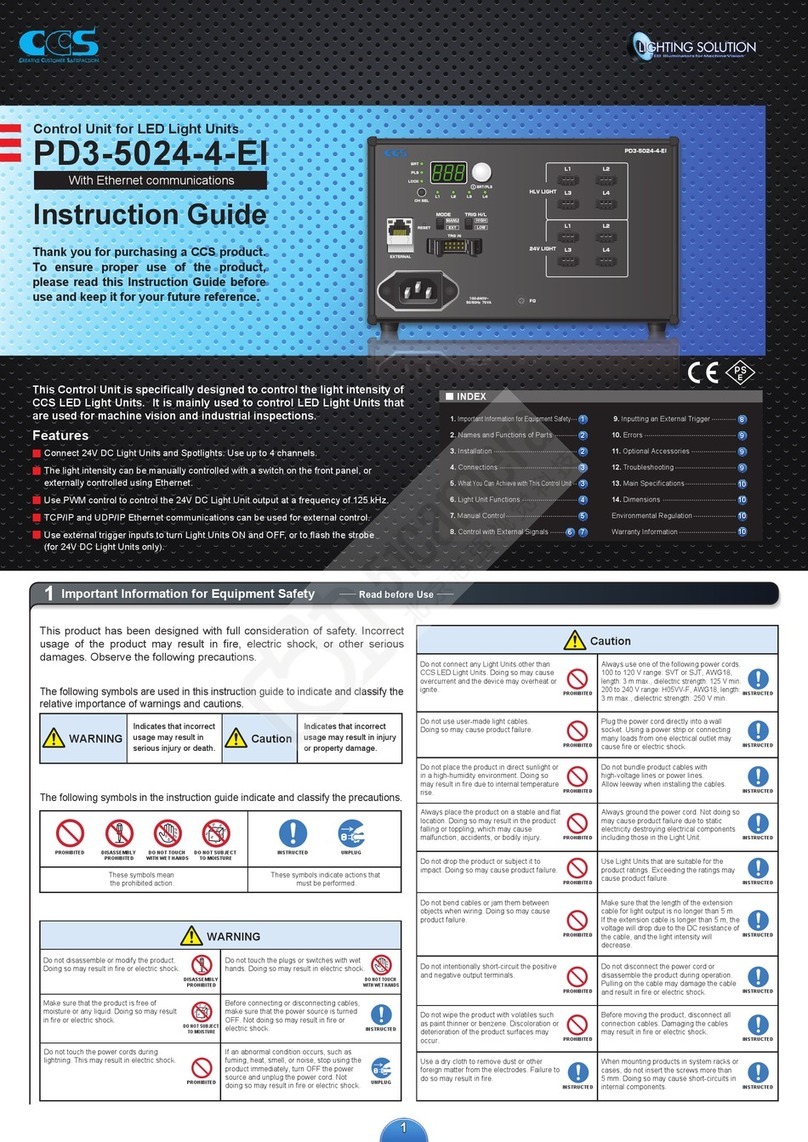
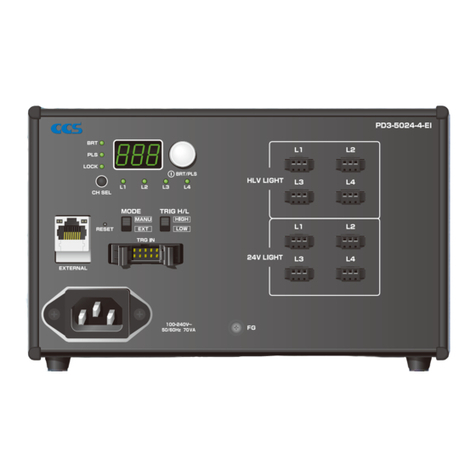
CCS Lighting Solution PD3-5024-4-EI Manual

CCS

CCS Lighting Solution PD3-5024-4-EI Manual

CCS Lighting Solution PD3-5024-4-EI Manual

CCS

CCS Lighting Solution PD3-5024-4-EI Manual

CCS PD3-10024-8-EI Manual

CCS

CCS PD3-10024-8-EI Manual

CCS PD3-3024-3-EI Manual

CCS

CCS PD3-3024-3-EI Manual

CCS PD3-10024-8-EI Manual

CCS

CCS PD3-10024-8-EI Manual

CCS PD3-3024-3-PT Manual

CCS

CCS PD3-3024-3-PT Manual

CCS PD2 Series Manual

CCS

CCS PD2 Series Manual

CCS PD3-5024-4-SI Manual

CCS

CCS PD3-5024-4-SI Manual

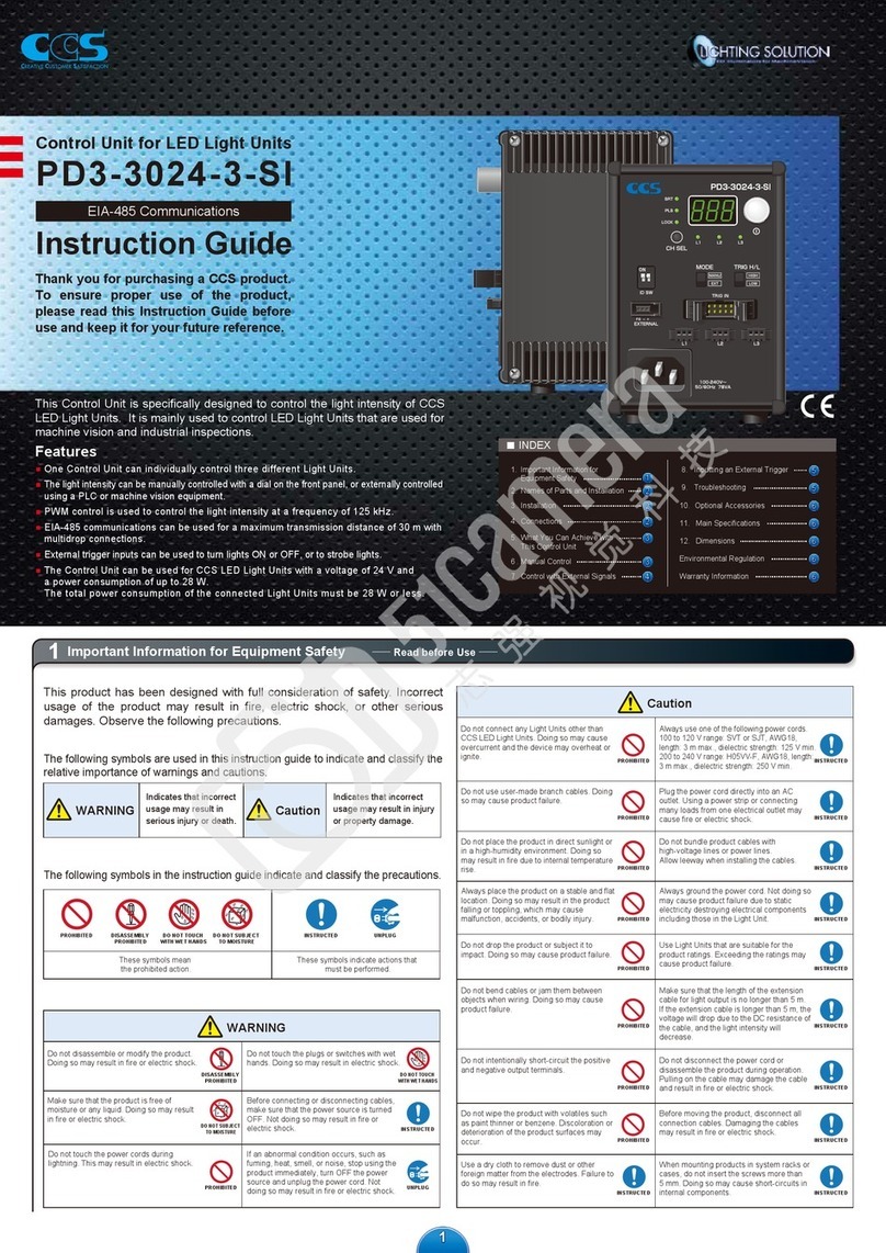
CCS PD3-3024-3-SI Manual

CCS

CCS PD3-3024-3-SI Manual

Popular Control Unit manuals by other brands

Midcontinent MD41 Serie Installation manual and operating instructions

Midcontinent

Midcontinent MD41 Serie Installation manual and operating instructions

Rexroth Indramat REFUdrive 500 RD51 operating instructions

Rexroth Indramat

Rexroth Indramat REFUdrive 500 RD51 operating instructions

Siemens SINUMERIK 805 operating instructions

Siemens

Siemens SINUMERIK 805 operating instructions

SinoCon KonNaD C2000-A2-SDXA000-AX1 user manual

SinoCon

SinoCon KonNaD C2000-A2-SDXA000-AX1 user manual

BENDIX PP-3 TRAILER SUPPLY VALVE manual

BENDIX

BENDIX PP-3 TRAILER SUPPLY VALVE manual

Tyco CV-1FR manual

Tyco

Tyco CV-1FR manual

Watts 800 Series Instructions for installing

Watts

Watts 800 Series Instructions for installing

american flame AF-LMF-RVS Installation and operation instruction

american flame

american flame AF-LMF-RVS Installation and operation instruction

Maker Factory ARDUINO MAKEVMA316 user manual

Maker Factory

Maker Factory ARDUINO MAKEVMA316 user manual

vistaCNC P2-S manual

vistaCNC

vistaCNC P2-S manual

Tranquil Ease HC-2H operating instructions

Tranquil Ease

Tranquil Ease HC-2H operating instructions

Teledyne CombiFlash Torrent installation guide

Teledyne

Teledyne CombiFlash Torrent installation guide

Spectrum Controls Micro800 2080sc-IF4U install guide

Spectrum Controls

Spectrum Controls Micro800 2080sc-IF4U install guide

hager WK305 User instructions

hager

hager WK305 User instructions

Advantech PCM-3345 manual

Advantech

Advantech PCM-3345 manual

Festo CPX-CMIX-M1-1 manual

Festo

Festo CPX-CMIX-M1-1 manual

opticis M2-100 user manual

opticis

opticis M2-100 user manual

Polycom VVX Series Quick reference guide

Polycom

Polycom VVX Series Quick reference guide

manuals.online logo
manuals.online logoBrands
  • About & Mission
  • Contact us
  • Privacy Policy
  • Terms and Conditions

Copyright 2025 Manuals.Online. All Rights Reserved.