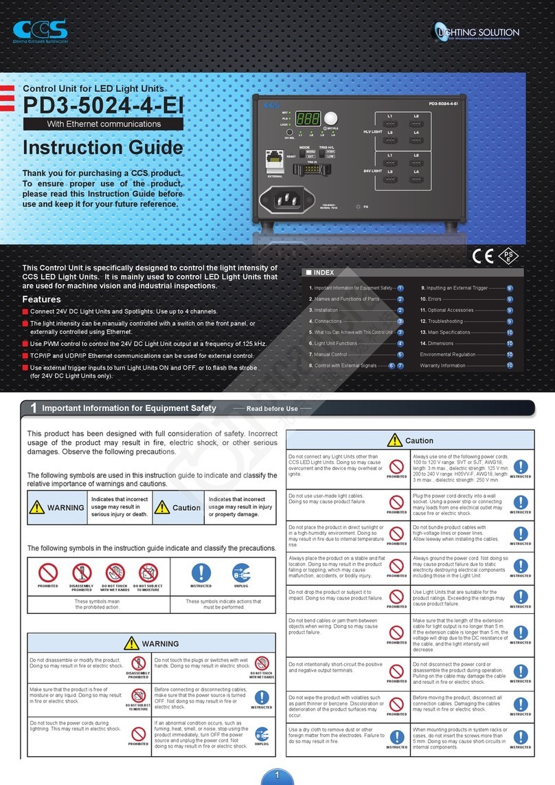
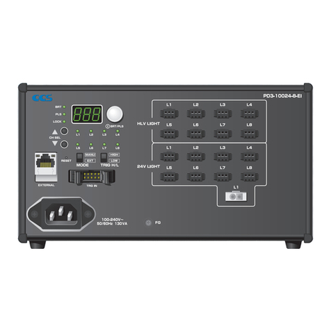
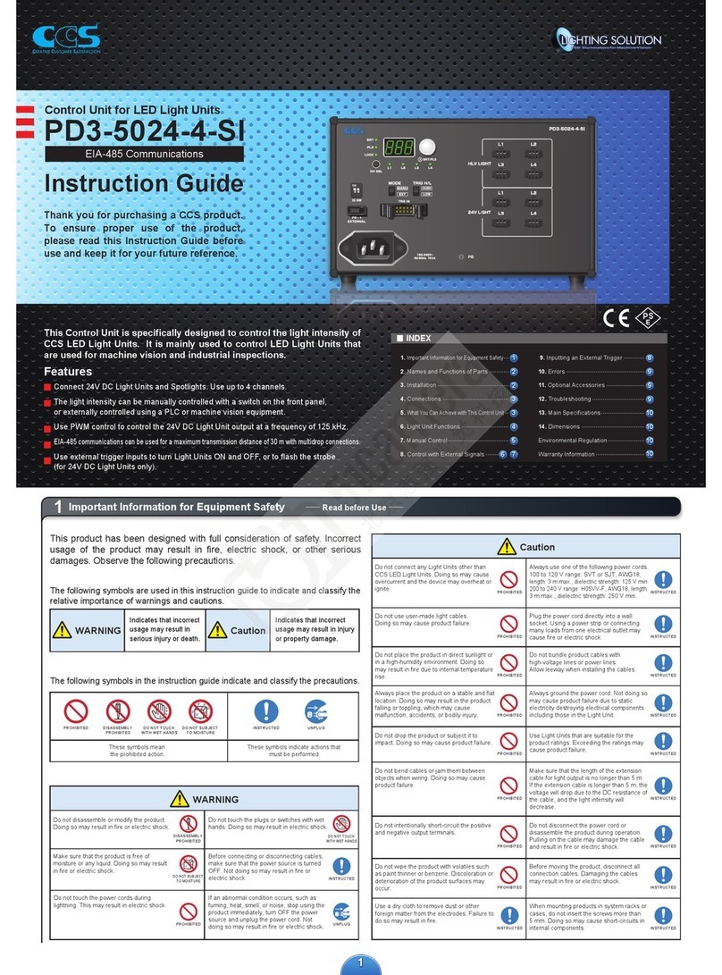
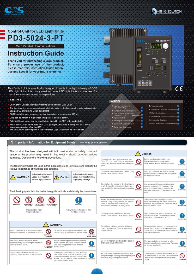
CCS PD3-10024-8-EI Manual

1
Connect 24V DC Light Units and Spotlights. Use up to 8 channels.
The light intensity can be manually controlled with a switch on the front panel,
or externally controlled using Ethernet.
Use PWM control to control the 24V DC Light Unit output at a frequency of 125 kHz.
TCP/IP and UDP/IP Ethernet communications can be used for external control.
Use external trigger inputs to turn Light Units ON and OFF, or to flash the strobe
(for 24V DC Light Units only).
PD3-10024-8-EI
Features
This Control Unit is specifically designed to control the light intensity of
CCS LED Light Units. It is mainly used to control LED Light Units that
are used for machine vision and industrial inspections.
Control Unit for LED Light Units
With Ethernet communications
Thank you for purchasing a CCS product.
To ensure proper use of the product,
please read this Instruction Guide before
use and keep it for your future reference.
Instruction Guide
Caution
INSTRUCTED
PROHIBITED
INSTRUCTED
PROHIBITED
INSTRUCTED
PROHIBITED
INSTRUCTED
PROHIBITED
INSTRUCTED
PROHIBITED
INSTRUCTED
PROHIBITED
INSTRUCTED
PROHIBITED
INSTRUCTED
INSTRUCTED
INSTRUCTED
PROHIBITED
The following symbols are used in this instruction guide to indicate and classify the
relative importance of warnings and cautions.
The following symbols in the instruction guide indicate and classify the precautions.
WARNING
WARNING
Indicates that incorrect
usage may result in
serious injury or death. Caution
Indicates that incorrect
usage may result in injury
or property damage.
PROHIBITED
PROHIBITED
DISASSEMBLY
PROHIBITED
DISASSEMBLY
PROHIBITED
DO NOT TOUCH
WITH WET HANDS
DO NOT TOUCH
WITH WET HANDS
These symbols mean
the prohibited action.
These symbols indicate actions that
must be performed.
DO NOT SUBJECT
TO MOISTURE
DO NOT SUBJECT
TO MOISTURE
INSTRUCTED
INSTRUCTED
UNPLUG
UNPLUG
This product has been designed with full consideration of safety. Incorrect
usage of the product may result in fire, electric shock, or other serious
damages. Observe the following precautions.
Do not touch the power cords during
lightning. This may result in electric shock.
Do not disassemble or modify the product.
Doing so may result in fire or electric shock.
Do not touch the plugs or switches with wet
hands. Doing so may result in electric shock.
Make sure that the product is free of
moisture or any liquid. Doing so may result
in fire or electric shock.
Before connecting or disconnecting cables,
make sure that the power source is turned
OFF. Not doing so may result in fire or
electric shock.
If an abnormal condition occurs, such as
fuming, heat, smell, or noise, stop using the
product immediately, turn OFF the power
source and unplug the power cord. Not
doing so may result in fire or electric shock.
Do not use user-made light cables.
Doing so may cause product failure.
Do not place the product in direct sunlight or
in a high-humidity environment. Doing so
may result in fire due to internal temperature
rise.
Always place the product on a stable and flat
location. Doing so may result in the product
falling or toppling, which may cause
malfunction, accidents, or bodily injury.
Do not intentionally short-circuit the positive
and negative output terminals.
Do not bend cables or jam them between
objects when wiring. Doing so may cause
product failure.
Do not wipe the product with volatiles such
as paint thinner or benzene. Discoloration or
deterioration of the product surfaces may
occur.
Do not drop the product or subject it to
impact. Doing so may cause product failure.
Use a dry cloth to remove dust or other
foreign matter from the electrodes. Failure to
do so may result in fire.
Do not connect any Light Units other than
CCS LED Light Units. Doing so may cause
overcurrent and the device may overheat or
ignite.
Always use one of the following power cords.
100 to 120 V range: SVT or SJT, AWG18,
length: 3 m max., dielectric strength: 125 V min.
200 to 240 V range: H05VV-F, AWG18, length:
3 m max., dielectric strength: 250 V min.
Plug the power cord directly into a wall
socket. Using a power strip or connecting
many loads from one electrical outlet may
cause fire or electric shock.
Do not bundle product cables with
high-voltage lines or power lines.
Allow leeway when installing the cables.
Always ground the power cord. Not doing so
may cause product failure due to static
electricity destroying electrical components
including those in the Light Unit.
Use Light Units that are suitable for the
product ratings. Exceeding the ratings may
cause product failure.
Make sure that the length of the extension
cable for light output is no longer than 5 m.
If the extension cable is longer than 5 m, the
voltage will drop due to the DC resistance of
the cable, and the light intensity will
decrease.
Do not disconnect the power cord or
disassemble the product during operation.
Pulling on the cable may damage the cable
and result in fire or electric shock.
Before moving the product, disconnect all
connection cables. Damaging the cables
may result in fire or electric shock.
When mounting products in system racks or
cases, do not insert the screws more than
5 mm. Doing so may cause short-circuits in
internal components.
1Important Information for Equipment Safety Read before Use
8
9
9
9
10
10
10
10
1
2
2
3
3
4
5
6
INDEX
1.
Important Information for Equipment Safety
2. Names and Functions of Parts
3. Installation
4. Connections
5.
What You Can Achieve with This Control Unit
6. Light Unit Functions
7. Manual Control
8. Control with External Signals
9. Inputting an External Trigger
10. Errors
11. Optional Accessories
12. Troubleshooting
13. Main Specifications
14. Dimensions
Environmental Regulation
Warranty Information
7

22
2Names and Functions of Parts
Pressed with a pointed object to reset
all settings to their default values.
External Control Reset Switch
Select the channel from L1 to L8. Only the channel
on which Light Units are connected can be selected.
The channels with same channel No. of 24V LIGHT
and HLV LIGHT are operated simultaneously.
Channel Selection Switch
Used for external control with Ethernet communications.
External Control Connector
External Trigger Input Connector
Ground the FG terminal.
FG Terminal
Connect these connectors to the 24V DC Light Units.
L1 to L8 (SMP-03V-BC), L1(ELR-02V)
Output Connectors
(24V LIGHT)
Fan Air Inlet (Left side)
This is the air inlet for the cooling fan.
Fan Exhaust Outlet (Right side)
This is the air outlet for the cooling fan.
Connect these connectors to the Spotlights.
L1 to L8 (SMP-03V-BC)
Output Connectors
(HLV LIGHT)
Setting Indicators
The indicator for the selected channel will light.
When the L1 indicator is lit, the settings for the L1 Light
Unit in the 24V Light Units (24V LIGHT) and the L1 Light
Unit in the Spotlights (HLV LIGHT) can be changed.
Channel Indicators
Press: Switches between the light intensity setting and lighting mode setting.
Press for at least 2 seconds: Locks the settings.
Rotate: Sets the light intensity or lighting mode.
Setting Switch
Displays the setting of the
light intensity or the setting of
the lighting mode.
Digital Window
Selects manual (MANU) or external (EXT) control mode.
Manual/External Mode Selector
Selects the logic of the trigger signal.
Trigger Logic Switch
Connects the power source to the Control Unit.
AC Inlet
3Installation
Do not place any objects within 20mm from the fan air inlets
or fan exhaust outlets. Insufficient ventilation may cause
heat to accumulate inside the product and result in a fire.
1Removing the Rubber Feet from the Bottom of the Unit
Remove the screws that hold the rubber feet in place using a Phillips
screwdriver.
2Securing the Brackets to the Base of the Unit
Secure the Brackets to the base of the Unit with the four screws that
come with the Brackets.
3Securing the Unit with Mounting Screws
Secure the Unit in place with mounting screws. The mounting screws must
be provided by the user.
Securing the Unit with Base Brackets (Accessories)
* Attach the Bracket to the other side as well.
Mounting the Unit to DIN Rail
Mounting to DIN Rail
Hook the tab on the upper part of the Unit on the DIN rail and press the
Unit in the direction indicated by arrow 2 while pressing it in the direction
indicated by arrow 1.
Removing from DIN Rail
Press the Unit down in the direction indicated by arrow 3 and pull it out in
the direction indicated by arrow 4.
DIN Rail
1
2
Rear
DIN Rail
3
4
70
Two, 3.5 dia.
holes
±0.2
±0.2
59.3
29
4-C2
40
Two, 4.5 dia.
holes
195
(1)
5
10
Model: BK-PD3
Base Brackets
DIN rail brackets x 2
Screws x 8
Always use Base Brackets (model: BK-PD3) when securing the Unit at
its base. If it is secured without the Brackets, the Unit may be damaged.
Do not remove the DIN rail brackets.
If they must be removed and attached
again, make sure that you use the original
screws (or M3 × 4 mm screws).
If other screws are used, they may
short-circuit internal components and
electric shock may occur.
Caution
WARNING
Mounting Removing
BRT lit: The light intensity can be set.
PLS lit: The lighting mode can be set.
LOCK lit: The settings are locked.
Inputs the ON/OFF signal for ON/OFF Mode.
Inputs the trigger signal for Strobe Mode.
Rubber foot
Installation screw holes
(Insert the screws to a depth of no more than 5 mm
and use a tightening torque of 0.3 N·m max.)
M3 screws for the rubber feet
Screws for securing the Brackets to the mounting surface
(Prepare the mounting screws yourself according to the installation conditions.)
M3 screws for mounting the Brackets (included with the Brackets)
Holes for the mounting screws (4.5 dia.)
Caution
Includes two Base Brackets and
four mounting screws (+ one spare screw)

33
Firmly insert the connector of the LAN cable.
1
2
Press the lock and pull out the connector.
4Connections
1Connect the LED Light
Connect the connecting cable to the LED Light Unit to the output connector on the Control Unit.
Connect 24V DC Light Units to the 24V LIGHT output connectors, and Spotlights to
the HLV LIGHT output connectors. One of the 24V LIGHT output connectors is an
ELR-02V connector for a High-output Light Unit.
Insert the connector to the Light Unit all the way in.
Press the lock and pull out the connector.
SMP-03V-BCSMP-03V-BC ELR-02VELR-02V
2Connect the AC Cord
The AC cord that is included with the Unit is for 100 to 120V AC. We recommend using the
following for 200 to 240V AC. Cable: GTCE-3 x 1.0 mm
2
(manufactured by Kawasaki Electric
Wire Company), Connector: KS-31AY (manufactured by Kawasaki Electric Wire Company)
Connect the power cord to the Control Unit and a wall socket. The Control Unit will turn ON when
power is supplied from the main power source. When the Unit is ON, the digital window will light.
3Connect the LAN Cable (Provided by the user)
To perform external control, connect the LAN cable to the external control connector.
The LAN cable must be provided by the customer. (Cable length should be within 30 m
at aximum.) This product recognizes either cross-cable or straight-cable automatically
by auto-negotiation function. Please reboot the product when changing the cable.
4
Connect the External Trigger Input Cable (Optional item, sold separately)
To use ON/OFF Mode or Strobe Mode, connect the external trigger input
cable to the external trigger input connector.
An optional External Trigger Input Cable (EXCB2-M10-3) (sold separately) is available.
In case using a self-made cable, cable length should be within 3 m at maximum.
Press the connector in until it locks in place.
Release the lock and remove the connector.
Digital Window
The light intensity of the
lowest channel is displayed.
(Display when no Light
Unit is connected)
1
2
1
2
Connect the AC power cord to the AC inlet and a wall socket.
Before connecting the Control Unit, make sure that the main
power source is turned OFF. Making connections with the
power turned ON may result in a fire or electric shock.
WARNING
Connecting Removing
Connecting Removing
Connecting Removing
*Data that has been
set is retained even
after the power is
turned OFF with
manual or external
control.
Select the control mode and lighting mode from the following Application Guide and proceed to the indicated reference items.
The Light Units are always ON.
Power ON
Power OFF
Lit.Not lit.
Control Mode
Lighting Mode
Application Guide
To use external control in Continuous Mode,
refer to items , , and under
.
1 32
8Control with External Signals
To use manual control in Continuous Mode, refer to
items , , and under .
7Manual Control
1 32
To use manual control in ON/OFF Mode,
refer to items , , and under
and
.
7Manual Control
13
2
9Inputting the External Trigger
The Light Units are turned ON for
a set time after the external trigger
signal is input.
Photocoupler OFF
Photocoupler ON
Lit. Not lit.Not lit.
* When the Trigger Logic
Switch is set to HIGH
Continuous ModeON/OFF Mode
Strobe Mode
Front panel operation External control using a PLC
or image process device
The Light Units are turned ON or
OFF according to the external
trigger signal input.
Photocoupler OFF
Photocoupler ON
Lit. Not lit.Not lit.
* When the Trigger Logic
Switch is set to HIGH
5What You Can Achieve with This Control Unit
* It is possible to turn LED light unit ON and
OFF by Ethernet communications, too.
External trigger signal or Ethernet
communications setting can be selected when
using ON/OFF mode by external control.
To use external trigger signal in ON/OFF mode,
refer to items , , and under
8Control with External Signals
9Inputting the External Trigger
1 2 3
and
.
To use Ethernet communications setting in ON/OFF mode,
refer to items , , , and under
1 2
8
Control with External Signals
35
.
To use manual control in Strobe Mode,
refer to items , , and under
and
.
9Inputting the External Trigger
7Manual Control
1 3 42
(Only 24V DC Light Units can be set.) (Only 24V DC Light Units can be set.)
To use external control in Strobe Mode,
refer to items , , , and under
and
.
1 3 42
9Inputting the External Trigger
8Control with External Signals
External Trigger Input Cable
(EXCB2-M10-3)
External Trigger Input Cable
(EXCB2-M10-3)
LAN cable
LAN cable
External Trigger Input Cable
(EXCB2-M10-3)
LAN cable
External Trigger Input Cable
(EXCB2-M10-3)
1
2
1

44
PWM control or lighting time control
8
1
Per connector: 60 W max.
95W max.
Depends on the power consumption of the Light Units.
Depends on which Light Units are connected/disconnected.
Detected when connected for the first time.
0.5 s
6Light Unit Functions
Item
Applicable illuminators
Lighting method
Lighting
mode
Control
mode
Number of
connectors
Rated
capacity
Lighting delay time
Channel selection
Light Unit connection detection
Power startup time
This Control Unit can be connected to Light Units and Spotlights with 24V DC inputs. Connect 24V DC Light Units to the 24V LIGHT connectors and
Spotlights to HLV LIGHT connectors. The functions vary with the Light Units that are connected. Check the following table before using the Light Units.
Continuous mode
ON/OFF mode
Strobe mode
Manual control
External control
SMP-03V-BC
ELR-02V
SMP-03V-BC
ELR-02V
Variable current control
---
8
---
Per connector: 3.9 W max. (700mA max.)
---
Depends on the light intensity of the Light Unit.
Only connected Light Units can be selected.
Detected at any time.
3 s
Light Units with 24V DC input voltage
10
5, 6
5, 6
5, 6
5
6, 7
2
2
10
10
8
5
5
10
10
Output Connectors (24V LIGHT)
Output Connectors (HLV LIGHT)
ELR-02V×1
* Rated capacity: 95 W max.
SMP-03V-BC×8
* Rated capacity per connector: 60 W max.
SMP-03V-BC×8
* Rated capacity per connector: 3.9 W max.
(700mA max.)
Total for all connectors×17
* Total rated capacity: 95 W max.
Spotlights24V DC Light Units
Spotlights: HLV2 series, HLV series*
*not including HLV-27 series/HLV-14- R/
HLV-14-GR/HLV-14- BL/HLV-14- SW
Reference
page

55
Locking Settings
When the setting switch is pressed for 2
seconds or longer, the lighting mode and
light intensity settings are locked, and the
LOCK setting indicator lights. (The set values
can be viewed.) Pressing the switch again for
2 seconds or longer releases the lock.
7Manual Control
Check
Make sure that the LOCK setting indicator is
not light and that the trigger logic switch is
set to HIGH. Otherwise you may not be able
to perform the rest of this procedure.
Set the Manual/External Mode Selector to MANU
to set Manual Mode.
1Setting the Manual/External Mode Selector to Manual
4Selecting the Lighting Mode (Continued)
4Selecting the Lighting Mode
Press the setting switch to light the PLS setting indicator.
Turn the setting switch to select the lighting mode from Continuous Mode,
ON/OFF Mode, or Strobe Mode. (Default value: F00 )
Turn the setting switch and set
F00
to turn ON the Light Units continuously.
To flash the strobe, turn the setting switch and select a setting from F01 to
F10 (strobe time of 40 μs to 40 ms). The Light Units are turned ON for the
period of time set on the setting switch after the external trigger signal is input.
The Strobe Mode can be set for 24V DC Light Units only.
Turn the setting switch and set F00 to turn the Light Units ON and OFF.
The Light Units are turned ON or OFF according to the external trigger signal input.
40μs
80μs
120μs
200μs
600μs
Strobe Mode
(The Strobe Mode can be set
for 24V DC Light Units only.) 1ms
4ms
10ms
20ms
40ms
Continuous Mode / ON/OFF Mode
Status
Digital Window
F01
F02
F03
F04
F05
F06
F07
F08
F09
F10
F00
3Setting the Light Intensity
Press the setting switch to light the BRT setting indicator.
Turn the setting switch to set a value between 0 and 255.
(Default setting: 255 , Minimum: 000 , Maximum: 255 )
Connector Connection Example
Even if the Light Unit is disconnected, the
channel can be selected until the power is
turned OFF. (The settings are also retained.)
Precautions for Channel Selection
Press.
Press for 2 s.
Continuous Mode
ON/OFF Mode (If the external trigger is not used, the Light Units are ON continuously.)
Strobe Mode (If an external trigger is not used, the Light Units are OFF.)
For details on the external trigger input, refer to 9. Inputting the External Trigger.
Press.
Make sure that the main power source is turned ON.
Set items , , and when using Continuous Mode or ON/OFF Mode.
Set items , , , and when using Strobe Mode.
1 3 42
1 32
* The light intensities are theoretical values.
24V LIGHT
0.4 (Dimly lit)
0.8
1.2
99.6
100.0
…
Light Intensity (%)
HLV LIGHT
0.0 (Not lit)
0.4
0.8
99.6
100.0
…
…
000
002
254
255
001
Digital Window
Eight channels from L1 to L8 are allocated to the 24V LIGHT and HLV
LIGHT output connectors. (The ELR-02V connector for 24V LIGHT is L1.)
When L1 is selected, settings for the L1 Light Unit for the 24V LIGHT connectors
(both SMP-03V-BC/ELR-02V) and the HLV LIGHT connectors can be changed.
The 8 channels can be controlled separately.
2Selecting the Channel
Press. Press.
Press the channel selection switch to select the channel to set (L1 to L8).
Press the channel selection switch , to select the Light Units in order from L1 to L8.
Press the channel selection switch , to select the Light Units in order from L8 to L1.
Only channels with Light Units connected to them can be selected.
(If a new Light Unit is connected, the lowest channel is automatically selected.)
Only channels with Light Units connected to them can be selected. If a Light Unit is removed
without turning OFF the power supply, the channel for the Light Unit that is no longer connected
may be selected. This does not indicate a malfunction. Check the following table for details.
There is risk of fire or electric shock. Make sure that the power supply is turned OFF when
you connect Light Units or Spotlights.
The channel with the
disconnected Light Unit
can be selected.
The Light Unit was disconnected
without turning OFF the power supply.
The channel with the
disconnected Light Unit
cannot be selected.
Operation
If there is an electrical connection,
the Light Unit will light.
(The channel can be selected.)
The Light Unit does not turn
ON or an HLV ID error occurs.
(The channel cannot be selected.)
A Light Unit that is not
supported was connected.
L1, L2, L4and L5
Channels
can be selected for the following connections:
and : L1, L2and L 4
: L1 and L5 .
L1, L2, L4, L5, L6, L7 and L8
Channels can be selected if the connections are changed to the following:
and
: L5, L6, and L7 : L 4 and L 8 without turning OFF the power supply.

66
8Control with External Signals
Specifications for External Control
Ethernet
RFC793, RFC768 RFC791 IEEE802.3, IEEE 802.3u, IEEE 802.3x 10BASE-T, 100BASE-TX
Specification
Communications Specifications (*1)
Command Formats
OK
<CR><LF>
NG
O00 to FF
(Refer to *8)
Receive Data (*10)
Send Data (*2)
Light Intensity Setting
Lighting Mode Setting
ON/OFF Setting
Setting Status Check
Error Status Check
All Channel Initialization
IP Address
Subnet Mask
Default Gateway
Reply IP Address
Reception Port Setting
Reply Port Setting
F
S
L
M
C
R
E01
E02
E03
E05
E04
E06
<CR><LF>
000 to 255 (Refer to *5)
00 to 10 (Refer to *6)
0: Not lit, 1: Lit (Refer to *7)
- - -
- - -
- - -
000.000.000.000 to 255.255.255.255
(Specify all digits, e.g., specify
“192.168.000.005”
instead of “192.168.0.5.”)
00000 to 65535
(Specify all digits, e.g., specify “04561”
instead of “4561.”)
00 to FF
(Refer to *8)
000
00
(Refer to *9)
- - -
- - -
- - -
192.168.000.002
255.255.255.000
192.168.000.001
192.168.000.016
40001
30001
<< Annotation>>
*1) The number of TCP connection (possible numbers to connect at same time) which PD3 correspond is “1”
*2) Send a data within 4 seconds from 'Header' to 'Delimiter', otherwise time-out error occurs and command data will be rejected.
*3) Specify all numbers in decimal format.
*4) Channel Specification
L2 L3L1
01 0200
L5 L6L4
04 05
L7
06
L8
0703
Eight channels from L1 to L8 are allocated to the 24V LIGHT and HLV LIGHT output connectors. (The ELR-02V connector for 24V LIGHT is L1.) When L1 is selected,
settings for the L1 Light Unit for the 24V LIGHT connectors (both SMP-03V-BC/ELR-02V) and the HLV LIGHT connectors can be changed. The 8 channels can be controlled separately.
*5) Light Intensity Settings The light intensity is controlled to any of 256 levels. 000 to 255 (000: Minimum, 255: Maximum)
000
0.0 (Not lit)
0.4 (Dimly lit)
Light intensity
(%) HLV LIGHT
24V LIGHT
001
0.4
002
0.8
254
99.6
255
100.0
0.8 1.2 99.6 100.0
Set the value to 00 to enter
Normal Mode and keep the Light
Unit lit continuously.
Set the value to 00 to enter ON/OFF Mode and turn the
Light Unit ON and OFF. The Light Units are turned ON or
OFF according to the external trigger signal input.
Select the lighting time from 01 to 10 (40 µs to 40 ms) to use a strobe light.
The Light Units are turned ON for the set time after the external trigger
signal is input. The Strobe Mode can be set for 24V DC Light Units only.
*6) Lighting Mode Settings Select the lighting mode form Continuous Mode, ON/OFF Mode, or Strobe Mode. The lighting time can be set in Strobe Mode.
(The Strobe Mode can be set for 24V DC Light Units only.) For details on the external trigger input, refer to 9. Inputting the External Trigger.
40μs 80μs 120μs 200μs 600μs 1ms 4ms 10ms 20ms 40ms
01 02 03 04 05 06 07 08 09 1000
* The light intensities are theoretical values.
TCP/UDP protocol IPv4 protocol
Standard Standard Standard Baud rate Transmission medium
10 Mbps/100 Mbps (Automatically detected.)
Protocol layer
(Set values that are higher than 07 are not valid.)
Channel
Set value
(Set values that are higher
than 10 are not valid.)
Strobe Mode
Digital window
Digital window
Set value
Set value
Continuous Mode
or ON/OFF Mode
Status
Function
Light Intensity Setting
Lighting Mode Setting
ON/OFF Setting
Setting Status Check
Error Status Check
All Channel Initialization
IP Address
Subnet Mask
Default Gateway
Reply IP Address
Reception Port Setting
Reply Port Setting
Function
Sent command
Instruction
Default
Data (*3) DelimiterChecksum
@
00 to 07
(Refer to *4)
FF: All channels
(ON/OFF setting only).
Header Channel specification
00 (fixed)
@
00 to 07
(Refer to *4)
FF: All channels
(ON/OFF setting only).
Header Channel specification
00 (fixed)
Received command
DelimiterChecksum
N
- - -
- - -
F999.S99.L9 (Refer to *11)
01: Command error
03: Set value out of range error
02: Checksum error
00: Normal, 11: Error
ABCDEFGHIJKLMNOPQRSTUVWXYZ 0123456789
Sample of Alphanumeric Characters:
Continuous Mode ON/OFF Mode
(If the external trigger is not used, the Light Units are ON continuously.)
Strobe Mode
(If an external trigger is not used, the Light Units are OFF.)

77
Set the Unit’s IP address and the reply address. To enable the settings that were changed, cycle the power supply.
* If the IP address changes, do not forget to change the send destination of commands.
Setting Up the Network (Only Initially and When Settings Are Changed)
2
IP Address
Subnet Mask
Default Gateway
Reception Port Setting
Reply IP Address
Reply Port Setting
192.168.3.2
255.255.255.0
192.168.3.1
4561
192.168.3.10
4562
@00E01192.168.003.00230CRLF
@00E02255.255.255.00035CRLF
@00E03192.168.003.00131CRLF
@00E040456149CRLF
@00E05192.168.003.01033CRLF
@00E06045624CCRLF
@00OEFCRLF
1Setting the Manual/External Mode Selector to External
Set the Manual/External Mode Selector to EXT to set External Mode. The value set with external control is displayed on the digital window.
* Although it is possible to set the external control setting even the manual/external mode selector is set to manual mode, the setting will not be activated until the
manual/external mode selector is set to external mode.
Setting the Light Intensity
Specify the channel and set the light intensity.
3
@02OF1CRLF @02N0151CRLF
@02F07584CRLF
Resetting the Light Intensity and Lighting Mode
@00OEFCRLF @00N014FCRLF
@00RF2CRLF
Checking the Unit Status
@00O004FCRLF @00N0351CRLF
@00CE3CRLF
Setting the Lighting Mode
4
@01OF0CRLF @01N0352CRLF
@01S0458CRLF
To Set ON/OFF Signal in ON/OFF Mode
5
@FFO1BCRLF @FFN027CCRLF
@FFL048CRLF
To Check the Setting Status
@00MEDCRLF @00N0250CRLF@00OF075.S04.L060CRLF
Setting Procedures
8Control with External Signals (Continued)
*9) Default setting for trigger logic switch is HIGH =‘1(ON)’ and LOW =‘0(OFF)’.
*10) There is no received data when timeout error occurs.
*11) Received command for setting status check (F999.S99.L9) F999=Light intensity setting (F000 to F255), S99=Lighting mode setting (S00 to S10), L9=ON/OFF setting (L0: Not lit / L1: Lit)
@ 0 1 F 1 2 5
*8) Checksum
*7) ON/OFF setting from Ethernet communications without regards to trigger logic switch, turned OFF at ‘0’ and ON at ‘1’. ON/OFF setting will not be held after turning the power off.
When operating Ethernet communications and trigger signal input at same time in ON/OFF mode.
When Trigger logic switch is at HIGH: if ether controls setting to OFF setting, Light unit will be turned OFF
When Trigger logic switch is at LOW: if ether controls setting to ON setting, Light unit will be turned ON
Initialize the Network Setting
If the IP address setting and others is incorrect, you will not be able to connect to the Control Unit. You will also not be able to reset the IP address
and others. If that occurs, use a pointed object to press the external control reset switch on the front panel to reset all settings to their default values.
To enable the reset settings, cycle the power supply
* The lowest byte (two characters) of 17F
is taken, so the checksum is 7F.
Example: Setting the Light Intensity of Channel 2 to 125
Byte 2Byte 1 Byte 3 Byte 4 Byte 5 Byte 6 Byte 7
40 hex 30 hex 31 hex 46 hex 31 hex 32 hex 35 hex
Header Sent commandChannel
17F hex
Total
ASCII (hexadecimal)
Character
The codes of the ASCII characters from the header to the
send command are added, the lowest byte is converted to
hexadecimal, and two characters are sent.
To restore the external control setting to default value, send the following command.
All Channel Initialization
(when there is a command error)
Send the following command to check the Unit status.
Checking the Unit status (normal)
(when there is a set value out of range error)
Setting example
Setting the L3 light
intensity to 75
Send data
Receive data when OK
Receive data when NG
Setting example Send data
Receive data when OK
Receive data when NG
Setting example Send data
Receive data when OK
Receive data when NG
Setting example Send data Receive data when OK
Receive data when NG
Setting Send data
Receive data when OK
Receive data when NG
Setting Send data
Receive data when OK
Receive data when NG
(when there is a command error)
Specify the channel and set the lighting mode.
Setting the L2 lighting mode
to 200 µs in Strobe Mode
(when there is a set value out of range error)
Specify the channel and set ON/OFF signal.
(When there is checksum error)
When checking the setting status, send the following command after specify the channel.
●Set items , , and when using Continuous Mode.
1 2 3
Set items , , , and when using ON/OFF Mode.
5
●1 2 3
Set items , , , and when using Strobe Mode.
1 3 42
●
Item Setting example Send data Receive data when OK Receive data when NG
@00N014FCRLF
(when there is a command error)
@00N0351CRLF
(when there is a set value
out of range error)
(If Intensity=75, Strobe mode=200μs, Light unit=OFF)
Make sure that the main power source is turned ON.●
To turn all light units OFF
To check the setting
status of L1.

88
HIGH OFF
LOW ON
HIGH OFF
LOW
HIGH
LOW ON
Inputting an External Trigger
9
Input Signal and Photocoupler
The input signal from the external trigger input connector can be used to control the
photocoupler inside the Unit to turn the LED Light Units ON and OFF or to control
strobe timing. The operation depends on the setting of the trigger logic switch.
9 7 5 3 1
10 8 6 4 2
Connector Layout
No.
Black 1
Red 1
Black 1
Red 1
Black 1
Red 1
Black 1
Red 1
Black 1
Red 1
Light Unit ON/OFF control input
(L1)
Light Unit ON/OFF control input
(L2)
Light Unit ON/OFF control input
(L3)
Light Unit ON/OFF control input
(L4)
Light Unit ON/OFF control input
(L5)
Light Unit ON/OFF control input
(L6)
Light Unit ON/OFF control input
(L7)
Light Unit ON/OFF control input
(L8)
Not used.
COMMON+
1
2
3
4
5
6
7
8
9
10
Orange
Orange
Gray
Gray
White
White
Yellow
Yellow
Pink
Pink
External Trigger Signal Connection Example
1
10
24V DC COMMON
12kΩ
22kΩ
Lighting Delay Time
The lighting delay time for lights connected to 24V LIGHT connectors depends on the power
consumption of the Light Unit. The lighting delay time for Spotlights connected to 24 HLV
LIGHT depends on the intensity of the Spotlights. Refer to the following graphs and tables.
* The data in the graphs show reference values when a Light Unit or Spotlight with a 5-m cable is used. (The values are for reference only.)
Lighting Delay Time (typ.)
Light Intensity
10% 20% 30% 40% 50% 60% 70% 80% 90% 100%
610μs 260μs 180μs 130μs 110μs 82μs 73μs 65μs 60μs 55μs
Light Intensity vs. Lighting Delay Time Characteristic (HLV LIGHT)
0
500
1000
1500
2000
2500
3000
3500
4000
4500
5000
020 40 60 80 100
Light Intensity (%)
10W 20W 30W 40W 50W 60W 70W 80W 90W 95W
6μs 7μs 8μs 9μs 10μs 11μs 12μs 13μs 14μs 14.5μs
Power Consumption vs. Lighting Delay Time Characteristic (24V LIGHT)
0
2
4
6
8
10
12
14
16
18
20
10 20 30 40 50 60 70 80 90 100
Power Consumption (W)
Lighting Delay Time (μs)Lighting Delay Time (μs)
Trigger Input Sequence Diagram
(Only 24V DC Light Units can be set.)
LitLitNot litNot lit Not litNot lit
Trigger Logic
Switch
ON/OFF
Mode
Input signal
Light Units ON
Light Units ON for the set time.
Light Units OFF
No change
Light Units OFF
No change
Light Units ON
Light Units ON for the set time.
Photocoupler Strobe Mode
External Trigger Input
Connector Plug
Enlarged Cable Diagram
Pink Red 1
Example: Pin No. 10, pink, red 1
Wire color Marks
Signal Cable (EXCB2-M10-3)
* If another trigger is input before the Light Unit turns OFF in Strobe Mode,
the starting point of the reentered trigger is taken as the start time and the
strobe light continues for the set time from that point.
ON/OFF Mode
Trigger Logic Switch Set to HIGH
The Light Units turn ON when the photocoupler is OFF, and OFF
when the photocoupler is ON.
Strobe Mode
Photocoupler OFF
Photocoupler ON
Light Unit status
Photocoupler OFF
Photocoupler ON
Light Unit status
Photocoupler OFF
Photocoupler ON
Light Unit status
Photocoupler OFF
Photocoupler ON
Light Unit status
Trigger Logic Switch Set to LOW
The Light Units turn ON when the photocoupler is ON, and OFF
when the photocoupler is OFF.
Trigger Logic Switch Set to HIGH
From the point where the photocoupler goes OFF, the Light Units are
turned ON for the set time (40 µs to 40 ms).
Trigger Logic Switch Set to LOW
From the point where the photocoupler goes ON, the Light Units are
turned ON for the set time (40 µs to 40 ms).
40 µs to 40 ms
40 µs to 40 ms
10 µs min.
Signal Specifications
Light Unit ON/OFF
control input L1
PD3 Control UnitExternal Circuits
Transistor (NPN)
open collector
Rated
input voltage
Maximum
input voltage
20us max. (24V LIGHT)
5ms max. (HLV LIGHT)
24V DC 26.4V DC 14.4V DC min./
3 mA max.
5V DC max./
1 mA max. 12 kΩ (per terminal)
ON voltage/
ON current
OFF voltage/
OFF current Lighting delay time Input impedance
* When operating trigger signal input and Ethernet communications at same time in ON/OFF mode.
When Trigger logic switch is at HIGH: if ether controls setting to OFF setting, Light unit will be turned OFF
When Trigger logic switch is at LOW: if ether controls setting to ON setting, Light unit will be turned ON
10 µs min.
Lit
LitNot litNot lit Not litNot lit
Lit
LitNot litNot lit Not litNot lit
Lit
LitNot litNot lit Not litNot lit
Lighting Delay Time (typ.)
Light Intensity
Refer to “Lighting delay time”.

99
10
Errors
If no Light Unit has ever been
connected to the same channel in the 24V
LIGHT connectors, EId will be displayed.
If a Light Unit is connected to the
same channel in the 24V LIGHT connectors,
“ .” is displayed. (“ ” is the set value.)
HLV ID Error
A Spotlight outside the ID range was
connected to an HLV LIGHT connector.
If the channel that is connected to a Spotlight that is
outside the ID range is selected, an error will be displayed.
Light Units that are connected to 24V
LIGHT connectors can be set normally.
Overcurrent Error
The current consumption of the Light
Unit exceeded 107% of the rating.
Fan Stop Error
The fan has stopped.
Output is
stopped.
Output is
stopped.
Normal
OR
(Example display)
Period
Check the rating of the
LED Light Unit. Connect
an LED Light Unit that is
within the rating.
Press and hold the
setting switch or
cycle the power.
Press and hold the
setting switch or
cycle the power.
Operation recovers
automatically.
Doing so may cause
product failure.
Consult a CCS
representative.
Check the Spotlight.
Connect a Spotlight
that is supported by
the Control Unit.
If an internal error occurs in the Control Unit, it is displayed on the digital window.
Refer to the following table and clear the error before using the Control Unit again.
11
Optional Accessories (Sold Separately)
Model: EXCB2-M10-3
External Trigger Input Cable
Connector: XG4M-1030-T (manufactured by OMRON)
Cut off on one end
10-pole MIL connector
5 dia.
9
12
10
3000 150+
0
12
Troubleshooting
Symptom Items to check for fixing the problem
External control is
not possible.
Unable to turn the
Light Unit ON and
OFF or use strobe
control.
Malfunctioning.
Fuming, extreme
temperature, smell,
noise, or other
abnormality.
Is the external control cable (LAN cable) inserted firmly
into the external control connector and an external device?
Was the command sent correctly?
Set the network settings and data correctly.
Is the external trigger input cable inserted firmly into the
external trigger input connector and an external device?
Are the external trigger input cable and external devices
wired correctly?
Check the connector configuration and correct the wiring.
Is the lighting mode set correctly?
Set the value to F00 for ON/OFF Mode.
Set the value to F01 to F10 for Strobe Mode.
Is the signal setting correct?
Check the setting method and sequence diagram.
Please use designated power sources with stable voltage.
Sharing power sources with inverters, motors, etc., may
cause malfunction.
Do not bundle product cables with high-voltage lines or power
lines. Doing so may cause the product to malfunction. Keep
the product cables as far away from such lines as possible.
There is a possibility of product failure. Please stop usage
immediately and turn OFF the power switch.
Please do not attempt to use or repair the product, since it
is dangerous, but contact CCS Inc.
If you have any problems during product usage, please look up the cause in this chart. If the situation does not improve, or an unexpected situation
occurs, please contact CCS Inc.
3
3
8
5, 6
6, 7
8
-
-
-
Symptom Items to check for fixing the problem Reference
page
Reference
page
Lights not
illuminating.
Light intensity
control is not
possible.
Are all power sources turned ON?
Is the LED light cable inserted firmly into the output connector?
Is the AC cord inserted firmly into the AC inlet and a wall
socket?
Does the digital window show an error?
Check the error display.
Is an appropriate Light Unit connected to the output
connector? Check the Light Unit.
Is the output connector the correct one for the connected
Light Unit? Connect 24V DC Light Units to the 24V LIGHT
connectors and Spotlights to HLV LIGHT connectors.
Is the lighting mode set correctly?
Set the lighting mode to F00 for Continuous Mode or
ON/OFF Mode.
Does the logic of the trigger signal match the trigger
signal setting switch?
Is the external trigger input OFF (in ON/OFF Mode or Strobe
Mode)? Check the setting method and sequence diagram.
Is the manual/external switch set correctly?
Set it to MANU to operate manually and to EXT for
external control.
Is an appropriate Light Unit connected to the output
connector? Check the Light Unit.
Is the output connector the correct one for the connected
Light Unit? Connect 24V DC Light Units to the 24V LIGHT
connectors and Spotlights to HLV LIGHT connectors.
Have the wrong channels been selected?
Check the channels whose lights are to be controlled.
Is the setting switch locked?
Press and hold the setting switch for more than two
seconds to release the lock.
3
3
3
4
5, 6
8
8
9
5, 6
4
4
4
5, 6
5
Digital Window
When detecting the error during external control, command will be received as
acknowledgement for checking status (over current confirmation) command “C”.
(This applies only to overcurrent errors and fan stop errors.)
Error Output
* Immediately after the error, occurrence of an error will be noticed only one time
by using UDP protocol. Notify data is the same as checking status (over current
confirmation) command “C”.
For details, refer to 8. Control with External Signals.
Error Status
Clearing the Error
Recovery Method

EU RoHS Directive
China RoHS Directive
*Standards for "RoHS Directive-Compliant Products"
Name and Amount of Toxic and Hazardous Substances or Elements
Lead
1000 ppm max.
Mercury
1000 ppm max.
Lead
(Pb)
Mercury
(Hg)
Cadmium
(Cd) (Cr (VI) )
PBB PBDE
Cadmium
100 ppm max.
Hexavalent chromium
1000 ppm max.
PBB
1000 ppm max.
PBDE
1000 ppm max.
(Items that are exempted in the RoHS Directive are excluded from these standards.)
Usage deadline
for environmental
protection Product name
Control Unit
for LED Lights
Toxic or hazardous substances and elements
Usage Deadline for Environmental Protection
产品中有毒有害物质或元素的名称及含量
铅
(Pb)
汞
(Hg)
镉
(Cd)
六价铬
(Cr (VI) )
环保
使用期限 产品
LED 照明
专用电源
有毒有害物质或元素
*Lead and cadmium are excluded in EU RoHS.
:表示该有毒有害物质在该部件所有均质材料中的含量均在 SJ/T11363-2006 标准规定的限量要求以下。
:表示该有毒有害物质至少在该部件的某一均质材料中的含量超出 SJ/T11363-2006 标准规定的限量要求。
此标志的数字是根据中华人民共和国电子信息产品污染控制管理办法以及有关标准等,表示该产品的环保使用期限的年数。
遵守产品的安全和使用上的注意,在产品使用后采取适当的方法根据各地法律,规定,回收再利用或进行废弃处理。
环保使用期限
(注) 铅和镉中的“×”,因欧洲 RoHS 没限定,故用“○”表示。
多溴联苯
(PBB)
多溴二苯醚
(PBDE)
Environmental Regulation
The RoHS Directive is short for the "restriction of use of certain hazardous substances in electrical and
electronic equipment." As a directive, it restricts the use of specific hazardous substances for new electrical and
electronic equipment marketed in the EU on or after July 1, 2006, and restricts the use of six substances,
which are (1) lead, (2) mercury, (3) cadmium, (4) hexavalent chromium, (5) polybrominated biphenyl (PBB),
and (6) polybrominated diphenyl ether (PBDE).
China RoHS Directive is formally known as "Management Methods for Controlling Pollution by Electronic
Information Products", which was implemented on March 1, 2007 in China. Same as EU RoHS Directive,
this regulation restricts the usage of six substances such as lead, mercury, cadmium, hexavalent chromium,
polybrominated biphenyl (PBB), and polybrominated diphenyl ether (PBDE). This regulation requires
electronic information products which are manufactured or imported, and sold in China, to clearly disclose
contents of the 6 restricted substances listed below.
Hexavalent
chromium
: Indicates that this toxic or hazardous substances contained in all the homogeneous materials for this part, according to
SJ/T11363-2006 is within the limit requirement.
: Indicates that this toxic or hazardous substance contained in all the homogeneous materials for this part, according to
SJ/T11363-2006, is over the limit requirement.
The number used in this logo is based on “Management Methods for Controlling Pollution by Electronic Information
Products” and related regulations from People’s Republic of China. It shows the product usage duration in years for
environmental protection. After finishing a product usage, the product needs to be re-used or discarded appropriately following
local law and regulations, complying with safety and usage caution.
Warranty Information
Copyright© 2011 CCS Inc. All Rights Reserved.
Descriptions in this instruction guide are based on information available as of November 2011. KZ03995-T001-001
Ask any product queries to the following address or to your nearest CCS representative.
Shimodachiuri-agaru, Karasuma-dori, Kamigyo-ku, Kyoto 602-8011 Japan
Phone : +81-75-415-8284 Fax : +81-75-415-8278 E-mail : intlsales@ccs-inc.co.jp
Headquarters
http://www.ccs-grp.com/mvad/
Do not use the product in the following situations.
medical equipment, amusement machines, or safety equipment.
Under conditions or in an environment not described in this instruction guide.
In nuclear energy control systems, railroad systems, aviation systems, vehicles, combustion equipment,
In applications involving serious risk to life or property, particularly applications demanding a high level of safety.
Contents of this Instruction Guide may be changed without prior notice.
Illustrations used in this Instruction Guide may differ from actual products.
CCS maintains the copyright on this Instruction Guide. Unauthorized transfer or reproduction is strictly prohibited.
Instruction Guide and Dimensional Diagrams in PDF or CAD can be downloaded from the CCS website.
http://www.ccs-grp.com/
EXCEPT FOR THE EXPRESS WARRANTIES STATED IN THIS DOCUMENT, CCS MAKES NO ADDITIONAL WARRANTIES,
EXPRESS, IMPLIED, OR STATUTORY, AS TO ANY MATTER WHATSOEVER. IN PARTICULAR, ANY AND ALL WARRANTIES
OF MERCHANTABILITY OR FITNESS FOR PARTICULAR PURPOSE ARE EXPRESSLY EXCLUDED.
EXCEPT AS EXPRESSLY SET FORTH HEREIN, CCS MAKES NO WARRANTIES WITH RESPECT TO THE PRODUCTS.
WARRANTY PERIOD: TWO YEARS, STARTING FROM CCS Inc. SHIPPING DATE.
CCS Inc. WILL REPAIR OR REPLACE THE PRODUCT FREE OF CHARGE IF IT SHOULD FAIL TO FUNCTION WITHIN THE
SPECIFIED WARRANTY PERIOD. IF EITHER OF THESE CONDITIONS OCCURS, PLEASE TAKE THE PRODUCT TO YOUR
CCS SALES REPRESENTATIVE.
WARRANTY TERMS
1 CCS Inc. WILL REPAIR OR REPLACE THE PRODUCT FREE OF CHARGE IF IT SHOULD FAIL TO FUNCTION UNDER USE
ON OUR SPECIFIED CONDITION IN ACCORDANCE WITH THE INSTRUCTION GUIDE AND OTHER WRITTEN CAUTIONS
DURING THE INDICATED WARRANTY PERIOD OF TWO YEARS.
2 CCS Inc. WILL CHARGE A REPAIR FEE UNDER THE FOLLOWING CONDITIONS:
1) IF THE PRODUCT HAS BEEN SUBJECTED TO MISUSE, UNAUTHORIZED REPAIRS, OR MODIFICATION FROM ITS
ORIGINAL DESIGN.
2) IF THE PRODUCT HAS BEEN DAMAGED FROM IMPACTS DUE TO INAPPROPRIATE HANDLING.
3) IF DAMAGE TO THE PRODUCT RESULTS FROM EXTERNAL CAUSES INCLUDING ACCIDENTS, FIRE, POLLUTION,
RIOTS, COMMUNICATION FAILURES, EARTHQUAKES, THUNDERSTORMS, WIND AND FLOOD DAMAGE, OR ANY
OTHER ACT OF PROVIDENCE, OR FROM ANY EXTRAORDINARY CONDITIONS SUCH AS ELECTRICAL SURGES,
WATER LEAKAGE, CONDENSATION, OR THE USE OF CHEMICALS.
4) IF THE DAMAGE RESULTS FROM CONNECTION TO ANY LED LIGHT UNIT OR TO ANY EQUIPMENT WHICH CCS Inc.
DOES NOT MANUFACTURE OR DOES NOT SPECIFY FOR USE.
3 CCS ASSUMES NO LIABILITY FOR ANY PURCHASER’S SECONDARY DAMAGE (DAMAGE OF EQUIPMENT, LOSS OF
OPPORTUNITIES, LOSS OF PROFITS, ETC.) OR ANY OTHER DAMAGE RESULTING FROM A FAILURE OF OUR
PRODUCT.
THIS WARRANTY INFORMATION PROVIDES THE SCOPE OF CCS'S PRODUCT WARRANTY WITHIN THE SPECIFIED
PERIOD, AND DOES NOT INDICATE OR IMPLY ANY FURTHER GUARANTEE BEYOND THE WARRANTY TERMS.
CONTACT CCS FOR INQUIRIES OR INFORMATION ON REPAIRS TO THE PRODUCT AFTER THE EXPIRATION OF THE WARRANTY.
Use our website to find your nearest CCS representative.
1010
Front View
Side View
Bottom View
13
Main Specifications
14
Dimensions
220
120
(6)
(1.8)
19214
1059.3
(6) (6)
82.6 (8)(13)
124
Product name
Model
Rated capacity
Input power supply
Inrush current (typ.)
Ground leakage current
Rated output voltage
Insulation withstand voltage
(input-output, input-FG)
Operating temperature and humidity
Storage temperature and humidity
Vibration resistance
Cooling method
CE Marking
PSE
Environmental regulations
Input connector
External control connector
Material and surface processing
Weight
Accessories
Digital Control Unit for LED Light Units (with Ethernet communications)
PD3-10024-8-EI
95 W max. for 17 connectors total
100 to 240V AC (+10%, −15%), 130 VA, 50/60 Hz
15 A (at 100V AC), 30 A (at 200V AC) from a cold start
3.5 mA max. (264V AC, 60 Hz, with no load)
24V DC
1,500V AC for one minute, Cutoff current: 10 mA,
500V DC, 20 MΩ min.
Temperature: 0 to 40°C, Humidity: 20% to 85% (with no condensation)
Temperature: −20 to 60°C, Humidity: 20% to 85% (with no condensation)
Acceleration: 19.6 m/s2, Frequency: 10 to 55 Hz, Cycles: 3 minutes,
Sweep cycle: For 1 hour each in X, Y, and Z directions
Forced air cooling
Safety standard: Conforms to EN 61010-1, EMC standard: Conforms to EN 61326, Class A.
Specified Electrical Appliance and Material(DC power supply units)Conformity with METI Ordinance Article 1
RoHS compliant
AC input: 3-pin inlet EN 60320-1 certified C14 type × 1
Trigger input: MIL connector (MIL-C-83503 compliant), 10-pole
For setting the light intensity and lighting mode: RJ-45
Material: Aluminum and resin, Surface processing: Blue alumite
1500 g max.
2-m long 3-pin power cord with ground terminal x1, Base Brackets x1 set, Instruction Guide x1
Specifications for Different Output Connectors
24V DC light units
60W max. (SMP-03V-BC/1 connector)
95W max. (ELR-02V)
PWM control (125kHz) or
lighting time control
Detected when connected
for the first time.
0.5 s
SMP-03V-BC (J.S.T. Mfg. Co., Ltd.) x 8
ELR-02V (J.S.T. Mfg. Co., Ltd.) x 1
Input type
Applicable
illuminators
Rated capacity
Lighting method
Light Unit
connection detection
Power startup time
Output
connectors
Spotlights: HLV2 series, HLV series*
*not including HLV-27 series/HLV-14-R/
HLV-14-GR/HLV-14-BL/HLV-14-SW
3.9W (700mA)max.
(SMP-03V-BC/1 connector)
Variable current control
Detected at any time.
3 s
SMP-03V-BC
(J.S.T. Mfg. Co., Ltd.) x 8
Four, M3 screws
(Insertion depth of 5 mm max.)
Four, M3 screws
(Insertion depth of 5 mm max.)
Other manuals for PD3-10024-8-EI
1
Table of contents
Other CCS Control Unit manuals
Popular Control Unit manuals by other brands

GESTRA
GESTRA CB 26 installation instructions

Sintai Optical
Sintai Optical 1DX Quick installation guide

EFI
EFI fiery EB-1357 Installation and service guide

Texas
Texas TSW1100 quick start guide

Paradyne
Paradyne iMarc SLV9128 installation instructions

SMAR
SMAR FY302 Operation, maintenance & instruction manual

Initiative Engineering
Initiative Engineering STM40FF quick start guide

ADLINK Technology
ADLINK Technology MPC-8164 user manual

Acromag
Acromag BusWorks XT Series user manual

Nordson
Nordson Encore HD Customer product manual

Dustcontrol
Dustcontrol DC 11 Original instructions

Kessel
Kessel Control Unit Ecolift 230V Instructions for installation, operation and maintenance