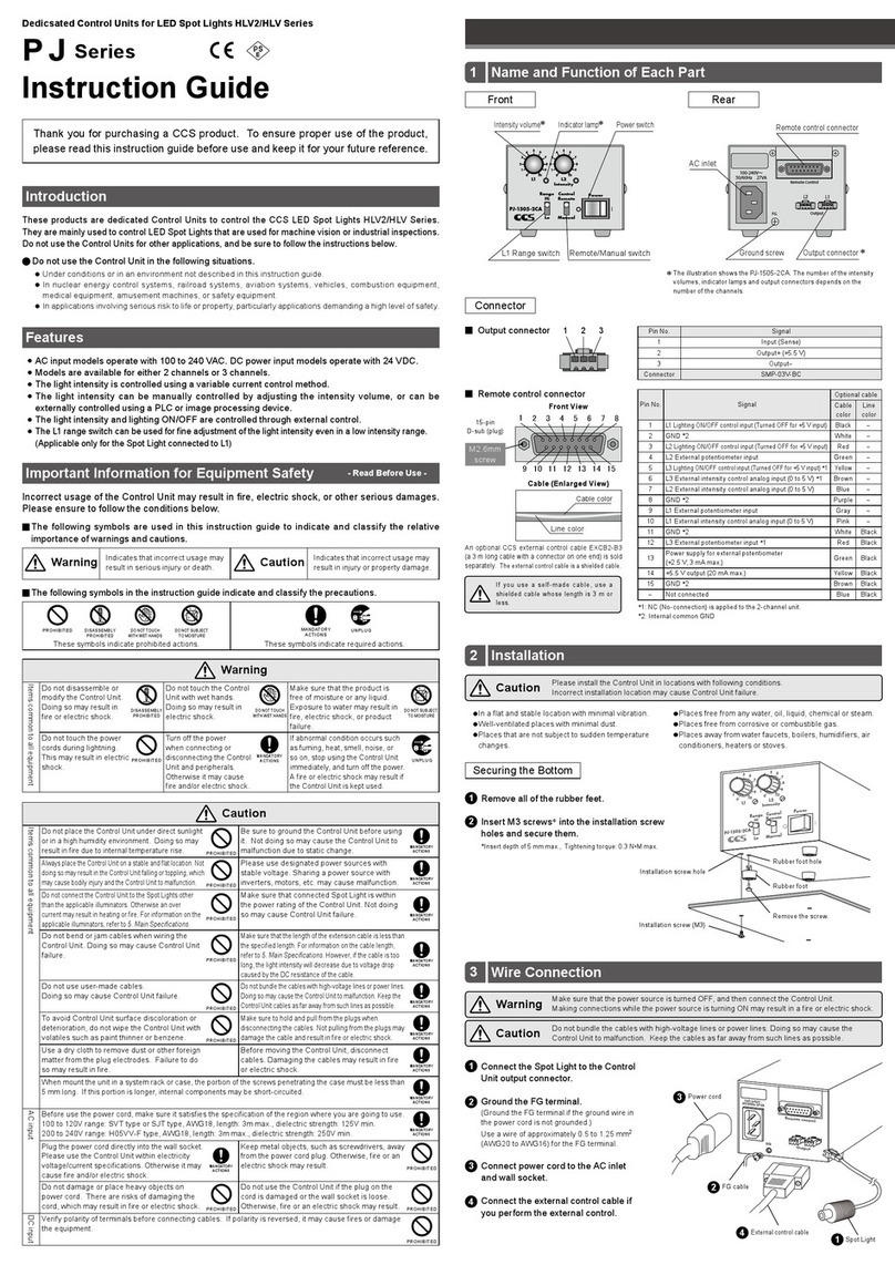
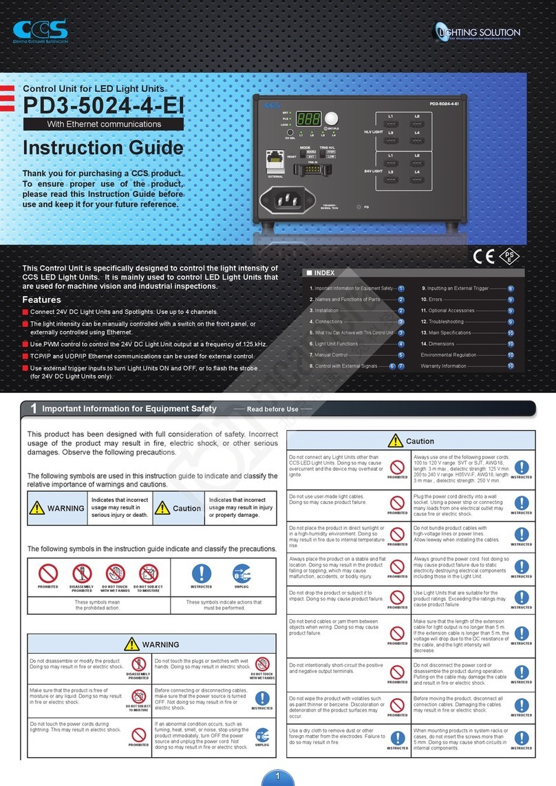
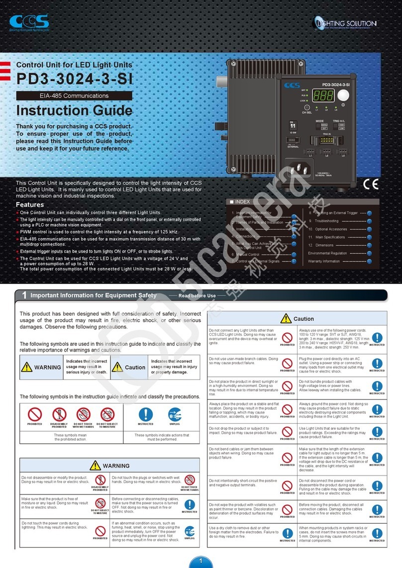
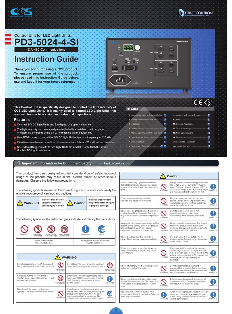
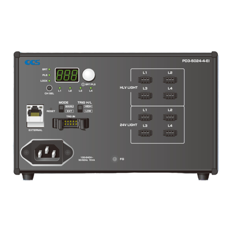
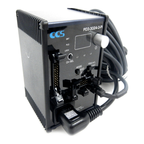
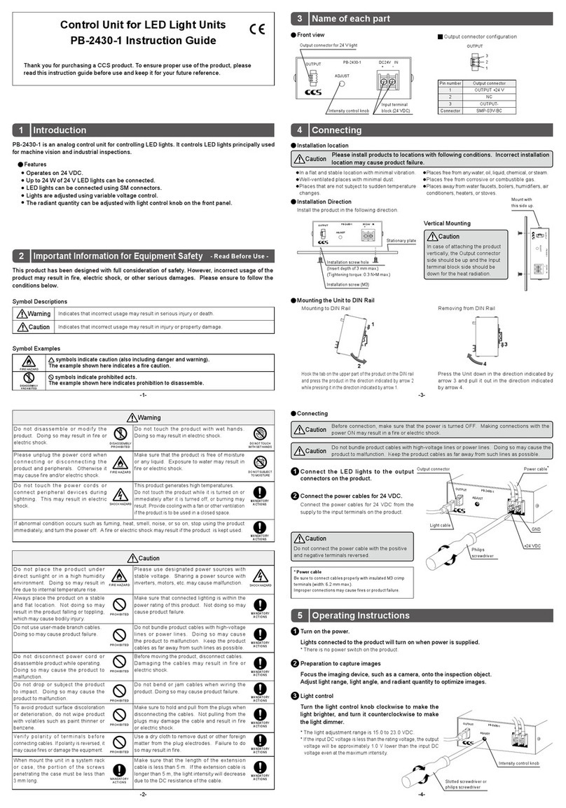
CCS PD3-5024-3-PT Manual

1
1Important Information for Equipment Safety
INDEX
1.
Important Information for
Equipment Safety
2. Names of Parts and Installation
3. What You Can Achieve with
This Control Unit
4. Manual Control
5. Inputting an External Trigger
6. Control with External Signals
7. Signal Input Sequences
8.
Troubleshooting
9. Optional Accessories
10. Main Specifications
11. Dimensions
Environmental Regulation
Warranty Information
Instruction Guide
Control Unit for LED Light Units
PD3-5024-3-PT
With Parallel Communications
Read before Use
Caution
The following symbols are used in this instruction guide to indicate and classify the
relative importance of warnings and cautions.
The following symbols in the instruction guide indicate and classify the precautions.
WARNING
WARNING
Indicates that incorrect
usage may result in
serious injury or death. Caution
Indicates that incorrect
usage may result in injury
or property damage.
PROHIBITED
PROHIBITED
DISASSEMBLY
PROHIBITED
DISASSEMBLY
PROHIBITED
DO NOT TOUCH
WITH WET HANDS
DO NOT TOUCH
WITH WET HANDS
These symbols mean
the prohibited action.
This symbol indicates actions that
must be performed.
DO NOT SUBJECT
TO MOISTURE
DO NOT SUBJECT
TO MOISTURE
INSTRUCTED
INSTRUCTED
INSTRUCTED
This product has been designed with full consideration of safety. Incorrect
usage of the product may result in fire, electric shock, or other serious
damages. Observe the following precautions.
Do not touch the power cords during
lightning. This may result in electric shock.
Do not disassemble or modify the product.
Doing so may result in fire or electric shock.
Do not touch the plugs or switches with wet
hands. Doing so may result in electric shock.
Make sure that the product is free of
moisture or any liquid. Doing so may result
in fire or electric shock.
Before connecting or disconnecting cables,
make sure that the power source is turned
OFF. Not doing so may result in fire or
electric shock.
If abnormal condition occurs such as fuming,
heat, smell, noise, or so on, stop using the
product immediately, and turn off the power
source. A fire or electric shock may result if
the product is kept used.
Thank you for purchasing a CCS product.
To ensure proper use of the product,
please read this Instruction Guide before
use and keep it for your future reference.
This Control Unit is specifically designed to control the light intensity of CCS
LED Light Units. It is mainly used to control LED Light Units that are used for
machine vision and industrial inspections.
Features
One Control Unit can individually control three different Light Units.
The light intensity can be manually controlled with a dial on the front panel, or externally controlled
using a PLC or machine vision equipment.
PWM control is used to control the light intensity at a frequency of 125 kHz.
Data can be written in high-speed with parallel external control.
External trigger inputs can be used to turn lights ON or OFF, or to strobe lights.
The Control Unit can be used for CCS LED Light Units with a voltage of 24 V and a
power consumption of up to 48 W.
The total power consumption of the connected Light Units must be 48 W or less.
24V DC IN
+ -
PROHIBITED
PROHIBITED
INSTRUCTED
PROHIBITED
PROHIBITED
INSTRUCTED
PROHIBITED
INSTRUCTED
INSTRUCTED
INSTRUCTED
INSTRUCTED
PROHIBITED
Do not use user-made branch cables. Doing
so may cause product failure.
Do not place the product in direct sunlight or
in a high-humidity environment. Doing so
may result in fire due to internal temperature
rise.
Always place the product on a stable and flat
location. Doing so may result in the product
falling or toppling, which may cause
malfunction, accidents, or bodily injury.
Do not bend cables or jam them between
objects when wiring. Doing so may cause
product failure.
Do not drop the product or subject it to
impact. Doing so may cause product failure.
Do not connect any Light Units other than
CCS LED Light Units. Doing so may cause
overcurrent and the device may overheat or
ignite.
Do not bundle product cables with
high-voltage lines or power lines.
Allow leeway when installing the cables.
Use Light Units that are suitable for the
product ratings. Exceeding the ratings may
cause product failure.
Use a standard Extension Cable that is
manufactured by CCS. However, if the
cable is too long, the light intensity will
decrease due to the DC resistance of the
cable.
Always hold onto the plug or connector
when disconnecting the cables. Pulling on
the cable may damage the cable and result
in fire or electric shock.
Before moving the product, disconnect all
connection cables. Damaging the cables
may result in fire or electric shock.
When mounting products in system racks or
cases, do not insert the screws more than
5 mm. Doing so may cause short-circuits in
internal components.
PROHIBITED
PROHIBITEDPROHIBITED
INSTRUCTED
Do not intentionally short-circuit the positive
and negative output terminals.
Do not wipe the product with volatiles such
as paint thinner or benzene. Discoloration or
deterioration of the product surfaces may
occur.
Be sure to use the product within the range
of input voltage. Applying the voltage beyond
the range may cause product failure.
Use a dry cloth to remove dust or other
foreign matter from the electrodes. Failure to
do so may result in fire.
5
1
2
2
3
3
4
5
6
6
6
6
6

22
2Names of Parts and Installation
3What You Can Achieve with This Control Unit
Displays the setting of the light intensity
or the setting of the lighting mode.
Selects manual (MANU) or external (EXT) control mode.
Digital Display
Setting Indicators
Press: Switches between the light intensity setting
and lighting mode setting.
Press for at least 2 seconds: Locks the settings.
Rotate: Sets the light intensity or lighting mode.
Setting Switch
Selects L1, L2, or L3.
Channel Selection Switch
For external control with parallel communications.
External Control Connector
Inputs the ON/OFF signal for ON/OFF Mode.
Inputs the trigger signal for Strobe Mode.
External Trigger Input Connector
BRT lit: The light intensity can be set.
PLS lit: The lighting mode can be set.
LOCK lit: The settings are locked.
Channel Indicators
L1 lit: Lit when changing settings for Light Unit connected to output connector L1.
L2 lit: Lit when changing settings for Light Unit connected to output connector L2.
L3 lit: Lit when changing settings for Light Unit connected to output connector L3.
Manual/External Mode Selector
Selects the logic of the trigger signal
Trigger Logic Switch
Supply power to the Light
Units.
Output Connectors
Connects the power source
to the Control Unit.
Terminal Block
Names and Functions of Parts
1Removing the Rubber Feet from
the Bottom of the Unit
Remove the screws that hold the rubber
feet in place using a Phillips screwdriver.
2Securing the Brackets to the Base
of the Unit
Secure the Brackets to the base of the
Unit with the four mounting screws that
come with the Brackets.
3
Securing the Unit with Mounting Screws
Secure the Unit in place with mounting screws.
The mounting screws must be provided by the user.
Mounting to DIN Rail
Hook the tab on the upper part of the Unit on
the DIN rail and press the Unit in the direction
indicated by arrow 2 while pressing it in the
direction indicated by arrow 1.
Removing from DIN Rail
Press the Unit down in the direction indicated
by arrow 3 and pull it out in the direction
indicated by arrow 4.
Mounting the Unit to DIN Rail
Securing the Unit with Base Brackets (Optional, Sold Separately)
Connections
Optional Cables Three models of optional cables (sold separately) are available.
External Control Cable (Model: EXCB2-M20-3) External Trigger Input Cable (Model: EXCB2-M10-3)
External Control/External Trigger Input Cable (Model: EXCB2-M10M20-3. The external control and external trigger input can be connected with one cable.)
1
3
2
4
Mounting
Removing
Always use Base Brackets (model: BK-PD3) when securing the Unit at its base.
If it is secured without the Brackets, the Unit may be damaged.
Output Connectors (L1 to L3)
Connecting Removing
Insert the connector to
the Light Unit all the
way in.
Press the lock and pull
out the connector.
External Trigger Input Connector (TRIG IN)
Connecting Removing
Press the connector in
until it locks in place.
Release the lock and
remove the connector.
External Control Connector (EXTERNAL)
Connecting Removing
Press the connector in
until it locks in place.
Release the lock and
remove the connector.
Select the control mode and lighting mode from the following Application Guide and proceed to the indicated reference items.
* Data that has been set is retained even after the power is turned OFF with manual or external control.
Before connecting the Control Unit, make sure that the main
power source is turned OFF.
Making connections with the power turned ON may result in a
fire or electric shock.
WARNING
The Light Units are always ON.
The Light Units are turned ON or
OFF according to the external
trigger signal input.
Power ON
Power OFF
Lit.Not lit.
The Light Units are turned ON for
a set time after the external trigger
signal is input.
Control mode
Lighting mode
Front panel operation External control using a PLC
or image process device
Application Guide
5Inputting the External Trigger
To use external control in Strobe Mode,
refer to items , , , and under
and
.
1 3 42
6Control with External Signals
To use external control in ON/OFF Mode,
refer to items , , and under
and
.
1 32
5Inputting the External Trigger
6Control with External Signals
To use external control in Continuous Mode,
refer to items , , and under
.
1 32
6Control with External Signals
5Inputting the External Trigger
To use manual control in ON/OFF Mode,
refer to items , , and under
and
.
4Manual Control
13
2
To use manual control in Continuous Mode, refer to
items , , and under .
4Manual Control
1 32
5Inputting the External Trigger
4Manual Control
To use manual control in Strobe Mode,
refer to items , , and under
and
.
1 3 42
Photocoupler OFF
Photocoupler ON
Lit. Not lit.Not lit.
* When the Trigger Logic
Switch is set to HIGH
Photocoupler OFF
Photocoupler ON
Lit. Not lit.Not lit.
* When the Trigger Logic
Switch is set to HIGH
Continuous ModeON/OFF Mode
Strobe Mode
Rubber foot
Installation screw holes
M3 screws for
the rubber feet
(Insert the screws to a depth of no
more than 5 mm and use a tightening
torque of 0.3 N·m max.)
Screws for securing the Brackets
to the mounting surface
(Prepare the mounting screws yourself
according to the installation conditions.)
M3 screws for mounting the Brackets
(M3, included with the Brackets)
Holes for the mounting screws
(4.5 dia.)
In case using a self-made cable, cable length should be within 3 m at maximum.
Terminal Block Cover
Attached to the Terminal Block in shipping.
Terminal Block
Connect the power cord to the Terminal Block and the main
power source, then attach the Terminal Block Cover onto the
Terminal Block.
The Control Unit will turn ON when power is supplied from
the main power source. When the Unit is ON, the digital
display will light.
● Be sure to connect cables properly with insulated M3 crimp
terminals (width: 6.2mm max.).
Improper connections may cause fires or product failure.
●
Pay attention to the polarity(+/-) when connecting the power cord.
Caution
1
2

33
4Manual Control
Inputting an External Trigger
Refer to 7. Signal Input Sequence for the sequence diagram.
5
Locking Settings
When the setting switch is pressed for
2 seconds or longer, the lighting mode and
light intensity settings are locked, and
the LOCK setting indicator lights. (The set
values can be viewed.) Pressing the switch
again for 2 seconds or longer releases the lock.
2Selecting the Channel
Press the channel selection switch to select the
channel to set (L1 to L3). The channel indicators
will change.
3Setting the Light Intensity
Press the setting switch to light the BRT setting
indicator.
Turn the setting switch to set a value between 0 and 255.
(Default setting: 000, Minimum: 000, Maximum: 255)
* The Light Units are light dimly at the minimum value.
1Setting the Manual/External Mode
Selector to Manual
Set the Manual/External Mode Selector to MANU
to set Manual Mode.
Make sure that the LOCK setting indicator is not light and that the trigger
logic switch is set to HIGH. Otherwise you may not be able to perform the
rest of this procedure.
Check
4Selecting the Lighting Mode
Press the setting switch to light the PLS
setting indicator.
Turn the setting switch to select the lighting
mode from Continuous Mode, ON/OFF Mode,
or Strobe Mode.
(Default value: F00 )
Continuous Mode
Turn the setting switch and set F00 to
turn ON the Light Units continuously.
ON/OFF Mode (If the external trigger is not used, the Light Units are ON continuously.)
Turn the setting switch and set F00 to turn the Light Units ON and OFF.
The Light Units are turned ON or OFF according to the external trigger signal input.
Strobe Mode
(If an external trigger is not used, the Light Units are OFF.)
To flash the strobe, turn the setting switch and
select a setting from F01 to F10
(strobe time of 40 μs to 40 ms).
The Light Units are turned ON for the period of time set
on the setting switch after the external trigger signal is input.
For details on the external trigger input, refer to 8. Inputting the External Trigger.
Digital display
F00 F01 F02 F03 F04 F05 F06 F07 F08 F09 F10
40 μs 80μs
120 μs 200 μs 600 μs
Strobe Mode
1 ms 4 ms 10 ms 20 ms 40 ms
Continuous Mode
ON/OFF Mode
Status
Make sure that the main power source is turned ON.
Set items , , and when using Continuous Mode or ON/OFF Mode.
Set items , , , and when using Strobe Mode.
1 3 42
1 32
Input Signal and Photocoupler
The input signal from the external trigger input connector can be used to control
the photocoupler inside the Unit to turn the LED Light Units ON and OFF or to
control strobe timing.
The operation depends on the setting of the trigger logic switch.
Setting Procedures
With the external trigger input connector pins 1
to 3, select the channels (L1 to L3) where you
want to input an external trigger, and input the
trigger.
Connector Layout
External Trigger Signal Connection Example
Trigger signals are input from the external trigger
input connector in ON/OFF Mode and Strobe
Mode are regardless of either Manual Mode or
External Mode.
ON/OFF Mode
The Light Units are turned ON or OFF according to
the external trigger signal input.
Strobe Mode
The Light Units are turned ON for the set time
after the external trigger signal is input.
9 7 5 3 1
10 8 6 4 2
1
2
3
Trigger Logic
Switch
ON/OFF
Mode
Input signal
HIGH OFF
Light Units ON
Light Units ON for the set time.
LOW ON
Light Units OFF
No change
HIGH OFF
Light Units OFF
No change
LOW
HIGH
LOW ON
Light Units ON
Light Units ON for the set time.
Photocoupler Strobe Mode
External Trigger Input Connector Plug
Enlarged Cable Diagram
Rated input voltage: 24 VDC
Maximum input voltage: 26.4 VDC
ON voltage/ON current: 14.4 VDC min./3 mA max.
OFF voltage/OFF current: 5 VDC max./1 mA max.
ON/OFF response time: 10 µs max.
Input impedance: 12 kΩ (per terminal)
Signal Specifications
Pink Red 1
Example: Pin No. 10, pink, red 1
Light Unit ON/OFF
control input
L1
24 VDC
Transistor (NPN)
open collector
Transistor (NPN)
open collector
Transistor (NPN)
open collector
COMMON+
PD3 Control UnitExternal Circuits
L3
L2
10
1
2
3
10
(COMMON+)
Light Unit ON/OFF
control input
Light Unit ON/OFF
control input
No.
Wire color
Cable
(EXCB2-M10-3/EXCB2-M10M20-3)
Marks
Signal
Light Unit ON/OFF control input (L1)
Light Unit ON/OFF control input (L2)
Light Unit ON/OFF control input (L3)
Not used.
COMMON+
- - - - - -
Orange
Orange
Gray
Pink
Black 1
Red 1
Black 1
Red 1
1
2
3
4 to 9
10
12kΩ
22kΩ
12kΩ
22kΩ
12kΩ
22kΩ

Input Signal and Photocoupler
The input signal from the external control
connector turns the photocoupler inside the
Control Unit ON and OFF to set and
write data. The input signal is compatible
with both the sinking and sourcing devices.
For a sinking device, the photocoupler is
OFF when the input signal is high, and for
a source type, the photocoupler is ON
when the input signal is high.
Signal input
HIGH OFF
LOW ON
HIGH ON
LOW
Sinking
Sourcing OFF
Photocoupler
No. Bit Signal
Wire
color Marks
1
2
3
4
5
6
7
8
9
10
11
12
13
14
15
16
17
18
19
20
B0
B1
B2
B3
B4
B5
B6
B7
CHSEL0
CHSEL1
CHSEL2
COMMON
BRTWR
TRGWR
M0
M1
M2
M3
OC
OE
Orange
Orange
Gray
Gray
White
White
Yellow
Yellow
Pink
Pink
Orange
Orange
Gray
Gray
White
White
Yellow
Yellow
Pink
Pink
Black 1
Red 1
Black 1
Red 1
Black 1
Red 1
Black 1
Red 1
Black 1
Red 1
Black 2
Red 2
Black 2
Red 2
Black 2
Red 2
Black 2
Red 2
Black 2
Red 2
Wire
color Marks
Orange
Orange
Gray
Gray
White
White
Yellow
Yellow
Pink
Pink
Orange
Orange
Gray
Gray
White
White
Yellow
Yellow
Pink
Pink
Black 2
Red 2
Black 2
Red 2
Black 2
Red 2
Black 2
Red 2
Black 2
Red 2
Black 3
Red 3
Black 3
Red 3
Black 3
Red 3
Black 3
Red 3
Black 3
Red 3
Light Intensity
Input (8 bits)
Lighting Mode
Value Input
(4 bits)
Error Output
Channel
Selection
(3 bits)
Light Intensity Write
Lighting Mode Write
Rated input voltage: 24 VDC
Maximum input voltage: 26.4 VDC
ON voltage/ON current: 14.4 VDC min./3 mA max.
OFF voltage/OFF current: 5 VDC min./1 mA max.
Response time: 50 µs max.
Input impedance: 12 kΩ (one terminal)
Connection Specifications
Specifications for External Control
Sinking
PD3 Control Unit
External Circuits
Sourcing
PD3 Control Unit
External Circuits
External Signal Connection Example
Connector Layout
External Control Connector Plug
Enlarged Cable Diagram
Pink Red 1
Example: Pin No. 10, pink, red 1
EXCB2-M20-3
EXCB2-M10M20-3
Cable
1
0
0
1
Data
Setting Procedures
Refer to 7. Signal Input Sequence for the sequence diagram.
Make sure that the main power source is turned ON.
Set items , , and when using Continuous Mode or ON/OFF Mode.
1 32 ●Set items , , , and when using Strobe Mode.
1 3 42
1
Setting the Manual/External Mode Selector to External
Set the Manual/External Mode Selector to EXT to set
External Mode. The value set with external control
is displayed on the digital display.
* Although it is possible to set the external control setting even the
manual/external mode selector is set to manual mode, the setting will not be
activated until the manual/external mode selector is set to external mode.
3Setting the Light Intensity
B7
Digital display
Radiant
quantity
0
0
0
1
1
0
1
2
254
255
B6
0
0
0
1
1
B5
0
0
0
1
1
B4
0
0
0
1
1
B3
0
0
0
1
1
B2
0
0
0
1
1
B1
0
0
1
1
1
B0
0
1
0
0
1
000
001
002
254
255
0: Photocoupler ON,
1: Photocoupler OFF
…
…
…
…
…
…
…
…
…
…
Dim
Bright
(COMMON)
There are 256 levels to the light intensity. Use pins 1
to 8 (B0 to B7) of the external control connector. Refer
to the following table for the settings.
Continue writing data. Input a signal to pin 13 (BRTWR)
that turns ON the photocoupler for at least 50 µs.
After that, turn the photocoupler OFF to complete writing.
(Default setting: 000, Minimum: 000, Maximum: 255)
Continuous Mode
Refer to the following table and set the lighting mode to Continuous Mode.
ON/OFF Mode
(If the external trigger is not used, the Light Units are ON continuously.)
Refer to the following table and set the lighting mode to ON/OFF Mode.
Th
e Light Units are turned ON or OFF according to the external trigger signal input.
Strobe Mode (If an external trigger is not used, the Light Units are OFF.)
The strobe time can be set to between 40 µs and 40 ms in Strobe Mode.
Refer to the following table for the settings.
The Light Units are turned ON for the set time after the external trigger signal is input.
18
M3
Digital display
No.
0
0
0
0
0
0
0
0
1
1
1
17
M2
0
0
0
0
1
1
1
1
0
0
0
16
M1
0
0
1
1
0
0
1
1
0
0
1
15
M0
0
1
0
1
0
1
0
1
0
1
0
F00
F01
F02
F03
F04
F05
F06
F07
F08
F09
F10
Lighting mode
Continuous Mode or ON/OFF Mode
Strobe Mode (40 µs)
Strobe Mode (80 µs)
Strobe Mode (120 µs)
Strobe Mode (200 µs)
Strobe Mode (600 µs)
Strobe Mode (1 ms)
Strobe Mode (4 ms)
Strobe Mode (10 ms)
Strobe Mode (20 ms)
Strobe Mode (40 ms)
0: Photocoupler ON,
1: Photocoupler OFF
* Pins 1011 to 1111 are not valid.
For details on the external trigger input, refer to 5. Inputting the External Trigger.
4Selecting the Lighting Mode
Select the lighting mode form Continuous Mode,
ON/OFF Mode, or Strobe Mode. Use pins 15 to 28
(M0 to M3) of the external control connector.
Refer to the following table for the settings.
(Default setting: F00 )
Continue writing data. Input a signal to pin 14 (TRGWR)
that turns ON the photocoupler for at least 50 µs.
After that, turn the photocoupler OFF to complete writing.
CHSEL2 CHSEL1
11 10
0 0
0 0
0 1
Bit
No.
L1
L2
L3
CHSEL0
9
0
1
0
2Selecting the Channel
0: Photocoupler ON,
1: Photocoupler OFF
* Pins 011 to 111 are not valid.
(COMMON)
Select the channel (L1 to L3) to set. Use pins 9 to 11
(CHSEL0 to CHSEL2) of the external control connector.
Refer to the following table for the settings. Input the write
signal and hold the setting status until writing is completed.
COMMON 12
1
COMMON 12
1
Transistor (NPN)
open collector
Light intensity input
B0
Light intensity input
B0
Transistor (PNP)
open collector
24 VDC
24 VDC
12kΩ
22kΩ
12kΩ
22kΩ
(COMMON)
6Control with External Signals
44

External Circuits
Trigger Input Sequence Diagram
Error Output
Error Output
Circuit Example
If another trigger is input before the Light Unit turns OFF in Strobe Mode, the starting point of the reentered trigger is taken as the start time and the strobe light continues for the set time from that point.
Normal operation
Pins 19 and 20 are open.
Error
Pins 19 and 20 are closed.
Rated input voltage: 24 VDC
Maximum input voltage: 26.4 VDC
Load current: 10 mA max.
Leakage current: 50 µA max.
Signal Specifications
Sequence Diagram for Writing Data
Channel Selection Input
CHSEL2 to CHSEL0
Light Intensity Write Input
BRTWR
Lighting Mode Write Input
Light Intensity Input
TRGWR
Photocoupler OFF
Photocoupler ON
Photocoupler OFF
Photocoupler ON
L1 light
set value
L2 light
set value
B7 to B0
Lighting Mode Value Input
M3 to M0
200 µs min. 300 µs min.
50 µs max.
50 µs min.
50 µs min.
50 µs min.
50 µs max.
50 µs min.
L1
Light intensity 1
L2
Light intensity 2
Lighting mode 2
Light intensity/lighting mode 1Light intensity/lighting mode 1
Light intensity/lighting mode 2
Lighting mode 1
Signal input
HIGH OFF
LOW ON
HIGH ON
LOW
Sinking
Sourcing OFF
Photocoupler
1
0
0
1
Data
Photocoupler OFF
Photocoupler ON
Photocoupler OFF
Photocoupler ON
Strobe Mode
Trigger Logic Switch Set to HIGH
From the point where the photocoupler goes OFF, the Light Units are
turned ON for the set time (40 µs to 40 ms).
Trigger Logic Switch Set to LOW
From the point where the photocoupler goes ON, the Light Units are
turned ON for the set time (40 µs to 40 ms).
Light Unit status
Light Unit status
10 µs max.
10 µs min.
40 µs to 40 ms
10 µs max.
10 µs min.
40 µs to 40 ms
Not lit.Not lit. Not lit.
Not lit.
Not lit.Not lit. Not lit.
Not lit.
Lit.Lit.
Lit.Lit.
Photocoupler OFF
Photocoupler ON
Photocoupler OFF
Photocoupler ON
ON/OFF Mode
Trigger Logic Switch Set to HIGH
The Light Units turn ON when the photocoupler is OFF, and OFF when
the photocoupler is ON.
Logic Switch Set to LOW
The Light Units turn ON when the photocoupler is ON, and OFF when
the photocoupler is OFF.
Light Unit status
Light Unit status Lit.Lit.Not lit.Not lit. Not lit.Not lit.
Not lit.
Not lit.
10 µs max. 10 µs max.
Lit.
Lit.Not lit.Not lit.
* Pins 1011 to 1111 are not valid.
8Troubleshooting
If the consumption current of Light Units exceeds 107% higher than the
rated current, the overcurrent protection operates and stops the output.
OCP will be displayed on the digital display.
Please check the rated current of Light Units and connect the Light Units
under the rated current of this control unit.
Please press Setting Switch for over a second to reset the OCP error.
(OCP error can be reset by rebooting.)
The error status is output from pins 19 and 20 of the external
control connector.
PD3 Control Unit
19
20
Photocoupler Error Output
OC
Error Output
OE
Error Output
Load current
7Signal Input Sequences
55
10 µs min.
40 µs min.
10 µs min.
40 µs min.
A pulse width of ON signal shall be 10μs or more. The Light Units will be truned on for at least 40μs, even when the input ON signal is less than 40μs.

Product name
Model
Applicable Light Unit rating
PWM frequency
Rated output voltage
Rated output current
Operating temperature and humidity
Storage temperature and humidity
Vibration resistance
Cooling method
CE Marking
Environmental regulations
Input connector
Output connectors
External Control
Connector
Material and surface processing
Weight
Accessories
Digital Control Unit for LED Light Units (with parallel communications)
PD3-5024-3-PT
24 V, 48 W
125 kHz
24 VDC
Total for 3 channels: 1.9 A
Temperature: 0 to 40°C, Humidity: 20% to 85% (with no condensation)
Temperature: −20 to 60°C, Humidity: 20% to 85% (with no condensation)
Acceleration: 19.6 m/s2, Frequency: 10 to 55 Hz, Cycles: 3 minutes,
Sweep cycle: For 1 hour each in X, Y, and Z directions
Natural air cooling
EMC standard: Conforms to EN 61326, Class A.
RoHS compliant
24 VDC input: 2-pin Terminal Block × 1
Light output: SMP-03V-BC (J.S.T. Mfg. Co., Ltd.) x 3
Trigger input: MIL connector (MIL-C-83503 compliant), 10-pole
For setting the light intensity/lighting mode: MIL connector (MIL-C-83503 compliant), 20-pole
Material: Aluminum and resin, Surface processing: Blue alumite
400 g max.
Instruction Guide
21 0
21 4
84
(6)
(1.8)
Front View
Model: EXCB2-M20-3
Connector: XG4M-2030-T (manufactured by OMRON)
External Control Cable
150+
3000 0
Cut off on one end
19
2
1
20
20-pole MIL connector
6.1 dia.
Connector: XG4M-1030-T (manufactured by OMRON)
Model: EXCB2-M10-3
External Trigger Input Cable
9
12
10-pole MIL connector
10
150+
3000 0
5 dia.
Cut off on one end
External control connector: XG4M-2030-T (manufactured by OMRON)
Trigger input connector: XG4M-1030-T (manufactured by OMRON)
Model: EXCB2-M10M20-3
External Control/External Trigger Input Cable (Common)
150+
3000 0
Cut off on one end
21
19 20
2
1
910
10-pole MIL connector
20-pole MIL connector
100
7.2 dia.
Model: BK-PD3
Base Brackets
70
Two, 3.5 dia. holes
±0.2
±0.2
59.3
29
4 2C-
40
Two, 4.5 dia. holes
195
(1)
5
10
Includes two Base Brackets
and four mounting screws
Input voltage (rated)
Power consumption (typ.)
24 VDC
Input voltage (range) 21.6 to 26.4 VDC
52W
82.6 (8)(13.7)
Side View Bottom View
56
Four, M3 screws
(Insertion depth
of 5 mm max.)
14
.95 3 10
(6) (6)
10
Main Specifications
11
Dimensions
9Optional Accessories (Sold Separately)
EU RoHS Directive
China RoHS Directive
*Standards for "RoHS Directive-Compliant Products"
Name and Amount of Toxic and Hazardous Substances or Elements
Lead
1000 ppm max.
Mercury
1000 ppm max.
Lead
(Pb)
Mercury
(Hg)
Cadmium
(Cd) (Cr (VI) )
PBB PBDE
Cadmium
100 ppm max.
Hexavalent chromium
1000 ppm max.
PBB
1000 ppm max.
PBDE
1000 ppm max.
(Items that are exempted in the RoHS Directive are excluded from these standards.)
Usage deadline
for environmental
protection Product name
Control Unit
for LED Lights
Toxic or hazardous substances and elements
Usage Deadline for Environmental Protection
产品中有毒有害物质或元素的名称及含量
铅
(Pb)
汞
(Hg)
镉
(Cd)
六价铬
(Cr (VI) )
环保
使用期限 产品
LED 照明
专用电源
有毒有害物质或元素
*Lead and cadmium are excluded in EU RoHS.
:表示该有毒有害物质在该部件所有均质材料中的含量均在 SJ/T11363-2006 标准规定的限量要求以下。
:表示该有毒有害物质至少在该部件的某一均质材料中的含量超出 SJ/T11363-2006 标准规定的限量要求。
此标志的数字是根据中华人民共和国电子信息产品污染控制管理办法以及有关标准等,表示该产品的环保使用期限的年数。
遵守产品的安全和使用上的注意,在产品使用后采取适当的方法根据各地法律,规定,回收再利用或进行废弃处理。
环保使用期限
(注)铅和镉中的“×”,因欧洲 RoHS 没限定,故用“○”表示。
多溴联苯
(PBB)
多溴二苯醚
(PBDE)
Environmental Regulation
The RoHS Directive is short for the "restriction of use of certain hazardous substances in electrical and
electronic equipment." As a directive, it restricts the use of specific hazardous substances for new electrical and
electronic equipment marketed in the EU on or after July 1, 2006, and restricts the use of six substances,
which are (1) lead, (2) mercury, (3) cadmium, (4) hexavalent chromium, (5) polybrominated biphenyl (PBB),
and (6) polybrominated diphenyl ether (PBDE).
China RoHS Directive is formally known as "Management Methods for Controlling Pollution by Electronic
Information Products", which was implemented on March 1, 2007 in China. Same as EU RoHS Directive,
this regulation restricts the usage of six substances such as lead, mercury, cadmium, hexavalent chromium,
polybrominated biphenyl (PBB), and polybrominated diphenyl ether (PBDE). This regulation requires
electronic information products which are manufactured or imported, and sold in China, to clearly disclose
contents of the 6 restricted substances listed below.
Hexavalent
chromium
: Indicates that this toxic or hazardous substances contained in all the homogeneous materials for this part, according to
SJ/T11363-2006 is within the limit requirement.
: Indicates that this toxic or hazardous substance contained in all the homogeneous materials for this part, according to
SJ/T11363-2006, is over the limit requirement.
The number used in this logo is based on “Management Methods for Controlling Pollution by Electronic Information
Products” and related regulations from People’s Republic of China. It shows the product usage duration in years for
environmental protection. After finishing a product usage, the product needs to be re-used or discarded appropriately following
local law and regulations, complying with safety and usage caution.
Warranty Information
Copyright© 2012 CCS Inc. All Rights Reserved.
Descriptions in this instruction guide are based on information available as of September 2012. KZ04003-T001-002
Ask any product queries to the following address or to your nearest CCS representative.
Shimodachiuri-agaru, Karasuma-dori, Kamigyo-ku, Kyoto 602-8011 Japan
Phone : +81-75-415-8284 Fax : +81-75-415-8278 E-mail : intlsales@ccs-inc.co.jp
Headquarters
http://www.ccs-grp.com/mvad/
Do not use the product in the following situations.
medical equipment, amusement machines, or safety equipment.
Under conditions or in an environment not described in this instruction guide.
In nuclear energy control systems, railroad systems, aviation systems, vehicles, combustion equipment,
In applications involving serious risk to life or property, particularly applications demanding a high level of safety.
Contents of this Instruction Guide may be changed without prior notice.
Illustrations used in this Instruction Guide may differ from actual products.
CCS maintains the copyright on this Instruction Guide. Unauthorized transfer or reproduction is strictly prohibited.
Instruction Guide and Dimensional Diagrams in PDF or CAD can be downloaded from the CCS website.
http://www.ccs-grp.com/
EXCEPT FOR THE EXPRESS WARRANTIES STATED IN THIS DOCUMENT, CCS MAKES NO ADDITIONAL WARRANTIES,
EXPRESS, IMPLIED, OR STATUTORY, AS TO ANY MATTER WHATSOEVER. IN PARTICULAR, ANY AND ALL WARRANTIES
OF MERCHANTABILITY OR FITNESS FOR PARTICULAR PURPOSE ARE EXPRESSLY EXCLUDED.
EXCEPT AS EXPRESSLY SET FORTH HEREIN, CCS MAKES NO WARRANTIES WITH RESPECT TO THE PRODUCTS.
WARRANTY PERIOD: TWO YEARS, STARTING FROM CCS Inc. SHIPPING DATE.
CCS Inc. WILL REPAIR OR REPLACE THE PRODUCT FREE OF CHARGE IF IT SHOULD FAIL TO FUNCTION WITHIN THE
SPECIFIED WARRANTY PERIOD. IF EITHER OF THESE CONDITIONS OCCURS, PLEASE TAKE THE PRODUCT TO YOUR
CCS SALES REPRESENTATIVE.
WARRANTY TERMS
1 CCS Inc. WILL REPAIR OR REPLACE THE PRODUCT FREE OF CHARGE IF IT SHOULD FAIL TO FUNCTION UNDER USE
ON OUR SPECIFIED CONDITION IN ACCORDANCE WITH THE INSTRUCTION GUIDE AND OTHER WRITTEN CAUTIONS
DURING THE INDICATED WARRANTY PERIOD OF TWO YEARS.
2 CCS Inc. WILL CHARGE A REPAIR FEE UNDER THE FOLLOWING CONDITIONS:
1) IF THE PRODUCT HAS BEEN SUBJECTED TO MISUSE, UNAUTHORIZED REPAIRS, OR MODIFICATION FROM ITS
ORIGINAL DESIGN.
2) IF THE PRODUCT HAS BEEN DAMAGED FROM IMPACTS DUE TO INAPPROPRIATE HANDLING.
3) IF DAMAGE TO THE PRODUCT RESULTS FROM EXTERNAL CAUSES INCLUDING ACCIDENTS, FIRE, POLLUTION,
RIOTS, COMMUNICATION FAILURES, EARTHQUAKES, THUNDERSTORMS, WIND AND FLOOD DAMAGE, OR ANY
OTHER ACT OF PROVIDENCE, OR FROM ANY EXTRAORDINARY CONDITIONS SUCH AS ELECTRICAL SURGES,
WATER LEAKAGE, CONDENSATION, OR THE USE OF CHEMICALS.
4) IF THE DAMAGE RESULTS FROM CONNECTION TO ANY LED LIGHT UNIT OR TO ANY EQUIPMENT WHICH CCS Inc.
DOES NOT MANUFACTURE OR DOES NOT SPECIFY FOR USE.
3 CCS ASSUMES NO LIABILITY FOR ANY PURCHASER’S SECONDARY DAMAGE (DAMAGE OF EQUIPMENT, LOSS OF
OPPORTUNITIES, LOSS OF PROFITS, ETC.) OR ANY OTHER DAMAGE RESULTING FROM A FAILURE OF OUR
PRODUCT.
THIS WARRANTY INFORMATION PROVIDES THE SCOPE OF CCS'S PRODUCT WARRANTY WITHIN THE SPECIFIED
PERIOD, AND DOES NOT INDICATE OR IMPLY ANY FURTHER GUARANTEE BEYOND THE WARRANTY TERMS.
CONTACT CCS FOR INQUIRIES OR INFORMATION ON REPAIRS TO THE PRODUCT AFTER THE EXPIRATION OF THE WARRANTY.
Use our website to find your nearest CCS representative.
66
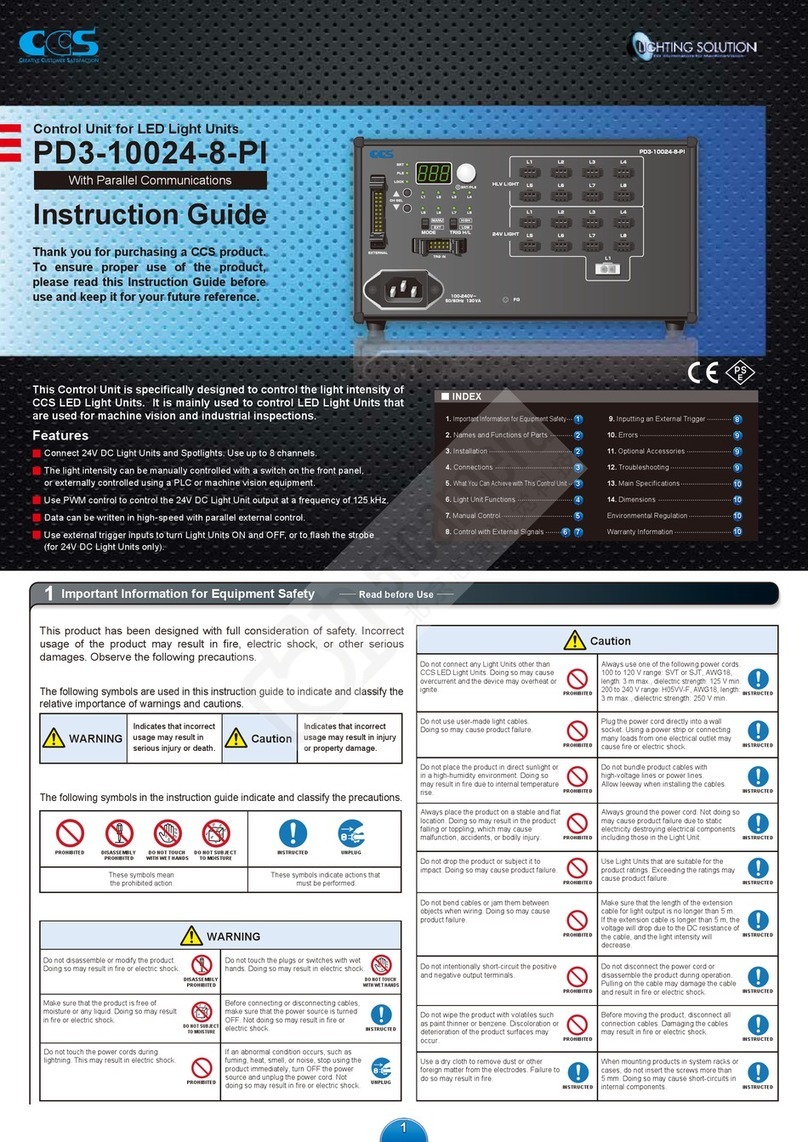
Table of contents
Other CCS Control Unit manuals
Popular Control Unit manuals by other brands

Vag
Vag GA INDUSTRIES Figures 251-D Installation, operation and maintenance manual

Beyerdynamic
Beyerdynamic Orbis SU 63 manual

Praher Plastics
Praher Plastics Aquastar MP6 pos manual

Burkert
Burkert 8697 operating instructions

RCS AUDIO-SYSTEMS
RCS AUDIO-SYSTEMS VARES LOOP TRT-300A operating instructions

GE
GE VersaSafe VersaPoint IC220SDL840 user manual