manuals.online logo
Brands
  1. Home
  2. •
  3. Brands
  4. •
  5. CDVI
  6. •
  7. Controllers
  8. •
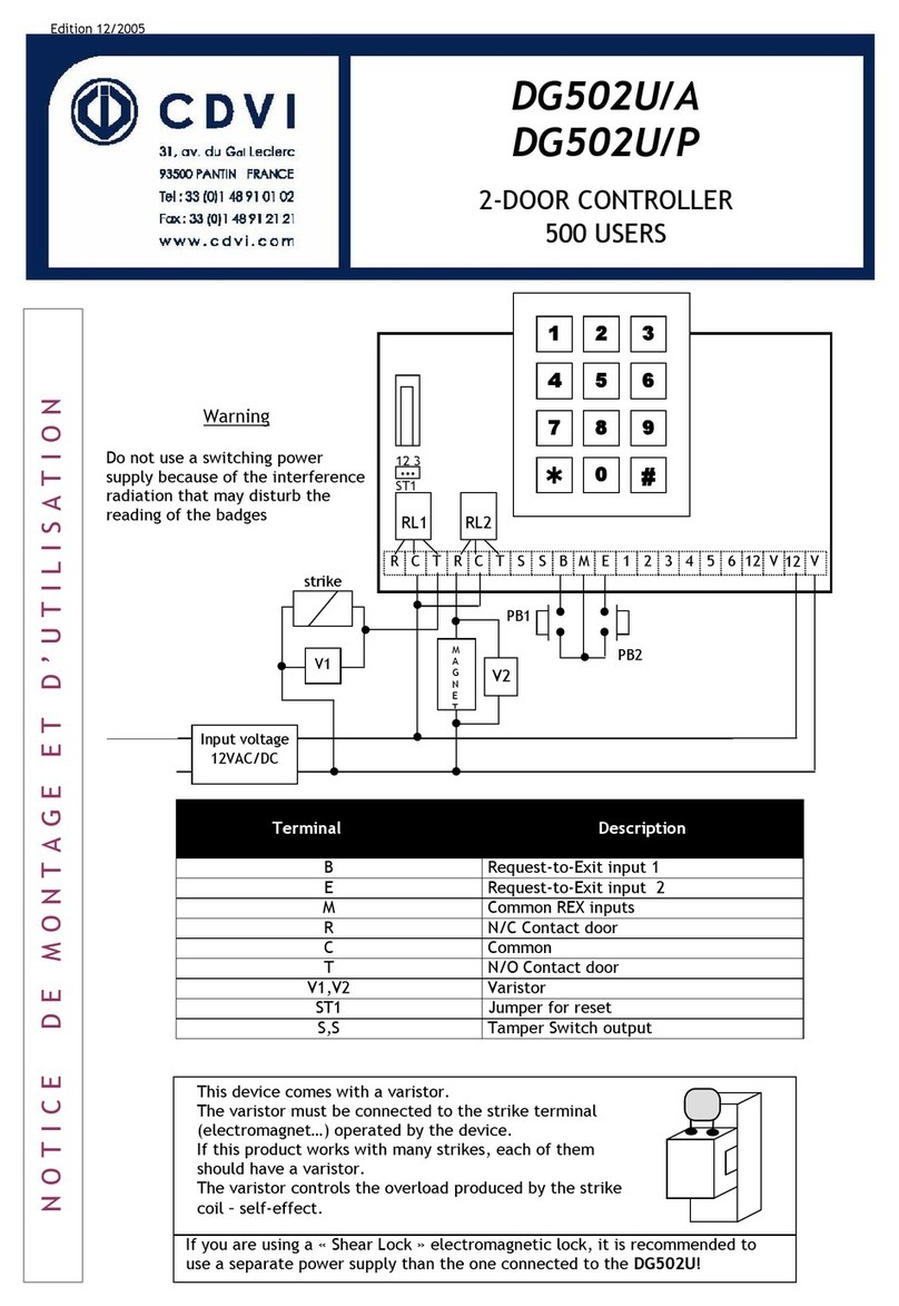
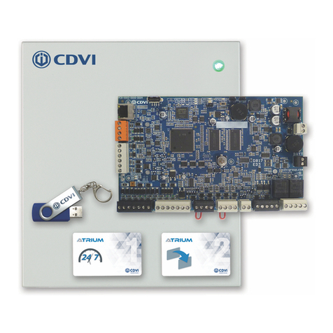
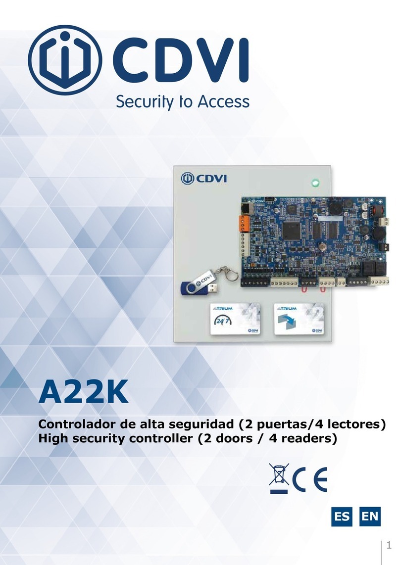
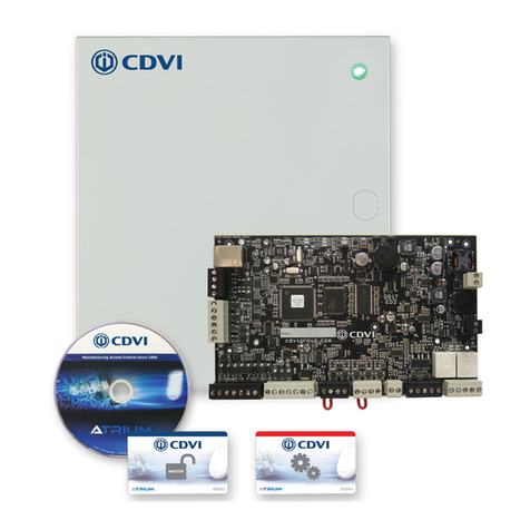
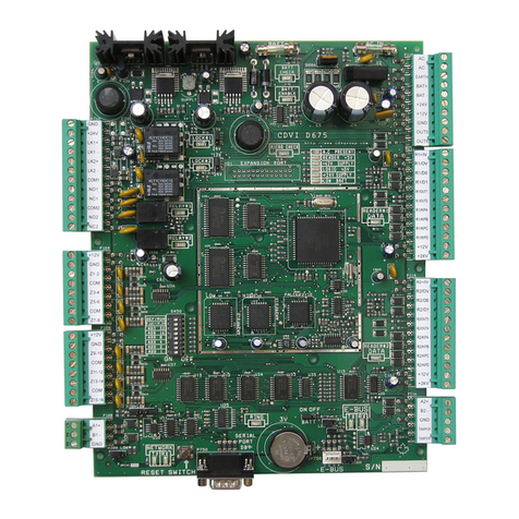
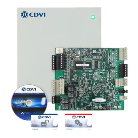
  9. CDVI ATRIUM A22K User manual

CDVI ATRIUM A22K User manual

QUICK START GUIDEQUICK START GUIDE
A22K 2-DOOR / 4-READER CONTROLLERA22K 2-DOOR / 4-READER CONTROLLER
LAN or WAN
BUZ GRN RED D1 D0 GND 12V BUZ GRN RED D1 D0 GND GNDC112V 12VREX1 GND GND C1 NO1 NC1LK1+ LK1- C2 NO2 NC2LK2+ LK2-TMPC2 12VREX2
+12V DC
+24V DC
-
+12V DC
-
+12V DC
A+
B-
Input 1
Input 2
Output 1
Output 2
BUZ GRNRED D1 D0 GND 12V BUZ GRNRED D1 D0 GND GNDC112V 12VREX1 GND GND C1 NO1NC1LK1+LK1- C2 NO2 NC2LK2+LK2-TMPC2 12VREX2
+12VDC
+24VDC
-
+12VDC
-
+12VDC
A+
B-
Input1
Input2
Output1
Output2
BUZ GRNRED D1 D0 GND 12V BUZ GRNRED D1 D0 GND GNDC112V 12VREX1 GND GND C1 NO1NC1LK1+LK1- C2 NO2 NC2LK2+LK2-TMPC2 12VREX2
+12VDC
+24VDC
-
+12VDC
-
+12VDC
A+
B-
Input1
Input2
Output1
Output2
BUZ GRNRED D1 D0 GND 12V BUZ GRNRED D1 D0 GND GNDC112V 12VREX1 GND GND C1 NO1NC1LK1+LK1- C2 NO2 NC2LK2+LK2-TMPC2 12VREX2
+12VDC
+24VDC
-
+12VDC
-
+12VDC
A+
B-
Input1
Input2
Output1
Output2
The ATRIUM A22K controller includes an embedded web server.
You can connect directly using your browser (PC, smartphone or
tablet) and do basic conguration, such as add / delete a user,
create and assign access levels to a user, etc. Simply install the
“ATRIUM Finder” application (Apple Store or Google Play) and
visit the CDVI website for all video tutorials on basic conguration
via the embedded web server:
https://www.cdvi.ca/cdvi-academy/videos/
Use the FREE ATRIUM software for advanced conguration
(PC only).
A22K FULL MANUAL
Scan the QR Code with your smartphone
for the full A22K manual
ATRIUM BASIC CONFIGURATION
Scan the QR Code with your smartphone for
the ATRIUM system configuration quick start guide
or visit CDVI website to download the manuals : www.cdvi.ca
POWER UP THE A22K CONTROLLER
VIDEO TUTORIALS ON ATRIUM SYSTEM CONFIGURATION
8
9
PLAN YOUR A22K NETWORK CONNECTIVITY
500 door system (100 doors connected IP + 400 doors connected RS485)
1
“MASTER”
CONTROLLER
The “Master” controller
manages up to forty nine (49)
“Sub-Controllers”.
(100 doors fully IP)
IP CONNECTIVITY
Out of the box the A22K is ready for IP connectivity, fty (50) A22K per account.
If you have more than one A22K controller per account, one must be set as
the “Master” controller to manage the others. These forty-nine (49) others are dened as “Sub-Controllers”.
RS485 CONNECTIVITY
An A22K can be set as an “Expander”. Up to four (4) can be connected to the
RS485 network (orange connector) of the “Master” and each “Sub-Controller”.
A22K “Master” or “Sub-Controllers”
RS485 port (orange connector).
A22K set as “Expander” A22K set as “Expander” A22K set as “Expander” A22K set as “Expander”
IP Network
Maximum 300 ft (100 m)
How to set an A22K as an “Expander”
On power OFF, move the “Module Type”
jumper setting to the two pins closest to “EX”.
DO NOT use IP connection
when an A22K is set as an
“Expander”.
Do not connect to a receptacle
controlled by a switch.
Simply plug the power cord into an AC electrical outlet.
LED on door metal enclosure illuminates green
when power is established.
Universal Power Supply specications:
Input: 120-240 VAC, 1.2 A, 50 Hz/60 Hz
Output: 24 VDC @ 2.5 A
“SUB-CONTROLLERS”
Up to forty-nine (49) A22K dened as “Sub-Controllers”.
EX CT
+12V DC
+24V DC
-
+12V DC
-
+12V DC
A+
B-
Input 1
Input 2
Output 1
Output 2
READER DOOR 1
INPUT
DOOR 1
LOCK
DOOR 1
LOCK
DOOR 2
INPUT
DOOR 2READER DOOR 2
ENCLOSURE
TAMPER
SWITCH
INPUT
BUZ GRN RED D1 D0 GND 12V BUZ GRN RED D1 D0 GND GNDC112V 12VREX1 GND GND C1 NO1 NC1LK1+ LK1- C2 NO2 NC2LK2+ LK2-TMPC2 12VREX2
+12V DC
+24V DC
-
+12V DC
-
+12V DC
A+
B-
Input 1
Input 2
Output 1
Output 2
INPUT
POWER
SUPPLY
RS485
LOCAL
BUS
ETHERNET
PORT
SYSTEM STATUS
EXTRA
INPUTS/
OUTPUTS
ETHERNET LOCAL BUS LOCK 1 & 2
JUMPER SETTING
STATUS
24V DC INPUT/
BATTERY/
MODULE TYPE
BATTERY
BACKUP
READER DOOR 1
INPUT
DOOR 1
LOCK
DOOR 1
LOCK
DOOR 2
INPUT
DOOR 2READER DOOR 2
ENCLOSURE
TAMPER
SWITCH
INPUT
BUZ GRN RED D1 D0 GND 12V BUZ GRN RED D1 D0 GND GNDC112V 12VREX1 GND GND C1 NO1 NC1LK1+ LK1- C2 NO2 NC2LK2+ LK2-TMPC2 12VREX2
Use twisted pair wiring
for RS485 connection
(1 pair for ground and 1
pair for A+ B-)
Maximum 4000 ft
(1220 m)
Communication between the
“Master” controller and
“Sub-Controllers” is
established via TCP/IP ONLY.
AES256
ENCRYPTION
QUICK START GUIDEQUICK START GUIDE
A22K 2-DOOR / 4-READER CONTROLLERA22K 2-DOOR / 4-READER CONTROLLER
CONNECT THE LOCK
5
+12V DC
+24V DC
-
+12V DC
-
+12V DC
A+
B-
Input 1
Input 2
Output 1
Output 2
INPUT
POWER
SUPPLY
RS485
LOCAL
BUS
ETHERNET
PORT
SYSTEM STATUS
EXTRA
INPUTS/
OUTPUTS
ETHERNET LOCAL BUS LOCK 1 & 2
JUMPER SETTING
STATUS
24V DC INPUT/
BATTERY/
MODULE TYPE
BATTERY
BACKUP
Door Strike
(Door 1)
READER DOOR 1
INPUT
DOOR 1
LOCK
DOOR 1
LOCK
DOOR 2
INPUT
DOOR 2READER DOOR 2
ENCLOSURE
TAMPER
SWITCH
INPUT
BUZ GRN RED D1 D0 GND 12V BUZ GRN RED D1 D0 GND GNDC112V 12VREX1 GND
GND C1 NO1 NC1LK1+ LK1- C2 NO2 NC2LK2+ LK2-TMP
C2 12VREX2
By default, the lock output is set for door strike (“Fail Secure”). The output
is at 0 VDC to keep the door locked and toggles to 12 VDC during 5 sec., on
access granted or request-to-exit, to unlock the door.
The A22K provides 12 VDC/750 mA for each door lock.
CONNECT K1 HIGH SECURITY CARD READER
4
+12V DC
+24V DC
-
+12V DC
-
+12V DC
A+
B-
Input 1
Input 2
Output 1
Output 2
INPUT
POWER
SUPPLY
RS485
LOCAL
BUS
ETHERNET
PORT
SYSTEM STATUS
EXTRA
INPUTS/
OUTPUTS
READER DOOR 1
INPUT
DOOR 1
LOCK
DOOR 1
LOCK
DOOR 2
INPUT
DOOR 2READER DOOR 2
ETHERNET LOCAL BUS LOCK 1 & 2
JUMPER SETTING
STATUS
24V DC INPUT/
BATTERY/
MODULE TYPE
BATTERY
BACKUP
ENCLOSURE
TAMPER
SWITCH
INPUT
Connection shown with
K1 KRYPTO High Security Card Reader
DOOR 1
ENTRY READER
Blue wire NOT connected
DOOR 1
EXIT READER (Optional)
Blue wire connected to A22K GND terminal
(Only required in the need to supervise the exit from an area)
Red
Black
Green
White
BUZ GRN RED D1 D0 GND 12V BUZ GRN RED D1 D0 GND GNDC112V 12VREX1 GND GND C1 NO1 NC1LK1+ LK1-
C2 NO2 NC2LK2+ LK2-
TMPC2 12VREX2
+12V DC
+24V DC
-
+12V DC
-
+12V DC
A+
B-
Input 1
Input 2
Output 1
Output 2
INPUT
POWER
SUPPLY
RS485
LOCAL
BUS
ETHERNET
PORT
SYSTEM STATUS
EXTRA
INPUTS/
OUTPUTS
ETHERNET LOCAL BUS LOCK 1 & 2
JUMPER SETTING
STATUS
24V DC INPUT/
BATTERY/
MODULE TYPE
BATTERY
BACKUP
READER DOOR 1
INPUT
DOOR 1
LOCK
DOOR 1
LOCK
DOOR 2
INPUT
DOOR 2READER DOOR 2
ENCLOSURE
TAMPER
SWITCH
INPUT
BUZ GRN RED D1 D0 GND 12V
BUZ GRN RED D1 D0 GND GNDC112V 12VREX1 GND GND C1 NO1 NC1LK1+ LK1- C2 NO2 NC2LK2+ LK2-TMPC2 12VREX2
Metal Enclosure
Wall Tamper Switch
(N.C.)
PCB
holder
Metal Enclosure
Door Tamper Switch
(N.C.)
CONNECT METAL ENCLOSURE TAMPER SWITCHES
3
FIX METAL ENCLOSURE & A22K PCB
2
CONNECT THE POWER SUPPLY TERMINAL & BACKUP BATTERY
7
+12V DC
+24V DC
-
+12V DC +
-
-
+12V DC
A+
B-
Input 1
Input 2
Output 1
Output 2
INPUT
POWER
SUPPLY
RS485
LOCAL
BUS
ETHERNET
PORT
SYSTEM STATUS
EXTRA
INPUTS/
OUTPUTS
ETHERNET LOCAL BUS LOCK 1 & 2
JUMPER SETTING
STATUS
24V DC INPUT/
BATTERY/
MODULE TYPE
BATTERY
BACKUP
BATT
READER DOOR 1
INPUT
DOOR 1
LOCK
DOOR 1
LOCK
DOOR 2
INPUT
DOOR 2READER DOOR 2
ENCLOSURE
TAMPER
SWITCH
INPUT
BUZ GRN RED D1 D0 GND 12V BUZ GRN RED D1 D0 GND GNDC112V 12VREX1 GND GND C1 NO1 NC1LK1+ LK1- C2 NO2 NC2LK2+ LK2-TMPC2 12VREX2
Red
Power Supply
LED Indicator
White
Red & black battery cables
are provided with the A22K
Always disconnect power
terminal prior to service
1 x Sealed Rechargeable
GEL Type Battery
12 VDC @ 7 Ah
CONNECT THE DOOR CONTACT & REQUEST-TO-EXIT
+12V DC
+24V DC
-
+12V DC
-
+12V DC
A+
B-
Input 1
Input 2
Output 1
Output 2
INPUT
POWER
SUPPLY
RS485
LOCAL
BUS
ETHERNET
PORT
SYSTEM STATUS
EXTRA
INPUTS/
OUTPUTS
ETHERNET LOCAL BUS LOCK 1 & 2
JUMPER SETTING
STATUS
24V DC INPUT/
BATTERY/
MODULE TYPE
BATTERY
BACKUP
N.C.
Com.
N.C.
Com.
N.C.
Com.
READER DOOR 1
INPUT
DOOR 1
LOCK
DOOR 1
LOCK
DOOR 2
INPUT
DOOR 2READER DOOR 2
ENCLOSURE
TAMPER
SWITCH
INPUT
BUZ GRN RED D1 D0 GND 12V BUZ
GRN RED D1 D0 GND GNDC112V 12VREX1 GND GND C1 NO1 NC1LK1+ LK1- C2 NO2 NC2LK2+ LK2-TMPC2 12VREX2
PRESS
TO EXIT
6
Install indoors in a safe and secure location.
Suggested locations are electrical rooms,
communication equipment rooms, closets or in the ceiling.
1. Fix the wall and door enclosure tamper switch
2. Install the metal enclosure on the wall
3. Mount the A22K pcb inside metal enclosure using
pcb holders (red circles on the drawing)
Remove the jumper from
the terminal before installing
the door contact
Refer to the full manual for the installation of lock
working on 24 VDC using our on-board dry contact
and an external power supply.
DOOR CONTACT
A door contact is required (default
N.C.) to monitor door status (open
or closed). It will generate an alarm
(card reader beeping and ashing
red) on a door forced event (access
not allowed) or door open too long.
REQUEST-TO-EXIT (REX)
Since a door contact is operational,
a REX is required (default N.C.)
in order to exit a door without
generating an alarm. The REX
could be a push button or motion
detector device.
Plug the two pin terminal, to which LED and
pre-installed universal power supply are connected,
to the A22K pcb input power supply.
Step 4, 5 & 6 show
the connection for door #1.
Do the same for door # 2
using its terminals.
+12V DC
+24V DC
-
+12V DC
-
+12V DC
A+
B-
Input 1
Input 2
Output 1
Output 2
INPUT
POWER
SUPPLY
RS485
LOCAL
BUS
ETHERNET
PORT
SYSTEM STATUS
EXTRA
INPUTS/
OUTPUTS
ETHERNET LOCAL BUS
LOCK 1 & 2
JUMPER SETTING
STATUS
24V DC INPUT/
BATTERY/
MODULE TYPE
BATTERY
BACKUP
Electromagnetic Door Lock
(Door 2)
Door Strike
(Door 1)
+
-
+
-
READER DOOR 1
INPUT
DOOR 1
LOCK
DOOR 1
LOCK
DOOR 2
INPUT
DOOR 2READER DOOR 2
ENCLOSURE
TAMPER
SWITCH
INPUT
BUZ GRN RED D1 D0 GND 12V BUZ GRN RED D1 D0 GND GNDC112V 12VREX1 GND GND C1 NO1 NC1LK1+ LK1- C2 NO2 NC2LK2+ LK2-TMPC2 12VREX2
12V0V
How to set the “Lock Output” for
Electromagnetic Lock (Maglock)?
On power OFF, move the “Lock Jumper Setting”
to the “12V” pins as shown here. The output
will be now at 12 VDC to keep the door locked
and toggles to 0 VDC during 5 sec., on access
granted or request-to-exit, to unlock the door.
QUICK START GUIDEQUICK START GUIDE
A22K 2-DOOR / 4-READER CONTROLLERA22K 2-DOOR / 4-READER CONTROLLER
LAN or WAN
BUZ GRN RED D1 D0 GND 12V BUZ GRN RED D1 D0 GND GNDC112V 12VREX1 GND GND C1 NO1 NC1LK1+ LK1- C2 NO2 NC2LK2+ LK2-TMPC2 12VREX2
+12V DC
+24V DC
-
+12V DC
-
+12V DC
A+
B-
Input 1
Input 2
Output 1
Output 2
BUZ GRNRED D1 D0 GND 12V BUZ GRNRED D1 D0 GND GNDC112V 12VREX1 GND GND C1 NO1NC1LK1+LK1- C2 NO2 NC2LK2+LK2-TMPC2 12VREX2
+12VDC
+24VDC
-
+12VDC
-
+12VDC
A+
B-
Input1
Input2
Output1
Output2
BUZ GRNRED D1 D0 GND 12V BUZ GRNRED D1 D0 GND GNDC112V 12VREX1 GND GND C1 NO1NC1LK1+LK1- C2 NO2 NC2LK2+LK2-TMPC2 12VREX2
+12VDC
+24VDC
-
+12VDC
-
+12VDC
A+
B-
Input1
Input2
Output1
Output2
BUZ GRNRED D1 D0 GND 12V BUZ GRNRED D1 D0 GND GNDC112V 12VREX1 GND GND C1 NO1NC1LK1+LK1- C2 NO2 NC2LK2+LK2-TMPC2 12VREX2
+12VDC
+24VDC
-
+12VDC
-
+12VDC
A+
B-
Input1
Input2
Output1
Output2
The ATRIUM A22K controller includes an embedded web server.
You can connect directly using your browser (PC, smartphone or
tablet) and do basic conguration, such as add / delete a user,
create and assign access levels to a user, etc. Simply install the
“ATRIUM Finder” application (Apple Store or Google Play) and
visit the CDVI website for all video tutorials on basic conguration
via the embedded web server:
https://www.cdvi.ca/cdvi-academy/videos/
Use the FREE ATRIUM software for advanced conguration
(PC only).
A22K FULL MANUAL
Scan the QR Code with your smartphone
for the full A22K manual
ATRIUM BASIC CONFIGURATION
Scan the QR Code with your smartphone for
the ATRIUM system configuration quick start guide
or visit CDVI website to download the manuals : www.cdvi.ca
POWER UP THE A22K CONTROLLER
VIDEO TUTORIALS ON ATRIUM SYSTEM CONFIGURATION
8
9
PLAN YOUR A22K NETWORK CONNECTIVITY
500 door system (100 doors connected IP + 400 doors connected RS485)
1
“MASTER”
CONTROLLER
The “Master” controller
manages up to forty nine (49)
“Sub-Controllers”.
(100 doors fully IP)
IP CONNECTIVITY
Out of the box the A22K is ready for IP connectivity, fty (50) A22K per account.
If you have more than one A22K controller per account, one must be set as
the “Master” controller to manage the others. These forty-nine (49) others are dened as “Sub-Controllers”.
RS485 CONNECTIVITY
An A22K can be set as an “Expander”. Up to four (4) can be connected to the
RS485 network (orange connector) of the “Master” and each “Sub-Controller”.
A22K “Master” or “Sub-Controllers”
RS485 port (orange connector).
A22K set as “Expander” A22K set as “Expander” A22K set as “Expander” A22K set as “Expander”
IP Network
Maximum 300 ft (100 m)
How to set an A22K as an “Expander”
On power OFF, move the “Module Type”
jumper setting to the two pins closest to “EX”.
DO NOT use IP connection
when an A22K is set as an
“Expander”.
Do not connect to a receptacle
controlled by a switch.
Simply plug the power cord into an AC electrical outlet.
LED on door metal enclosure illuminates green
when power is established.
Universal Power Supply specications:
Input: 120-240 VAC, 1.2 A, 50 Hz/60 Hz
Output: 24 VDC @ 2.5 A
“SUB-CONTROLLERS”
Up to forty-nine (49) A22K dened as “Sub-Controllers”.
EX CT
+12V DC
+24V DC
-
+12V DC
-
+12V DC
A+
B-
Input 1
Input 2
Output 1
Output 2
READER DOOR 1
INPUT
DOOR 1
LOCK
DOOR 1
LOCK
DOOR 2
INPUT
DOOR 2READER DOOR 2
ENCLOSURE
TAMPER
SWITCH
INPUT
BUZ GRN RED D1 D0 GND 12V BUZGRN RED D1 D0 GND GNDC112V 12VREX1 GND GND C1 NO1 NC1LK1+ LK1- C2 NO2 NC2LK2+ LK2-TMPC2 12VREX2
+12V DC
+24V DC
-
+12V DC
-
+12V DC
A+
B-
Input 1
Input 2
Output 1
Output 2
READER DOOR 1
INPUT
DOOR 1
LOCK
DOOR 1
LOCK
DOOR 2
INPUT
DOOR 2READER DOOR 2
ENCLOSURE
TAMPER
SWITCH
INPUT
BUZ GRN RED D1 D0 GND 12V BUZ GRN RED D1 D0 GND GNDC112V 12VREX1 GND GND C1 NO1 NC1LK1+ LK1- C2 NO2 NC2LK2+ LK2-TMPC2 12VREX2
+12V DC
+24V DC
-
+12V DC
-
+12V DC
A+
B-
Input 1
Input 2
Output 1
Output 2
INPUT
POWER
SUPPLY
RS485
LOCAL
BUS
ETHERNET
PORT
SYSTEM STATUS
EXTRA
INPUTS/
OUTPUTS
ETHERNET LOCAL BUS LOCK 1 & 2
JUMPER SETTING
STATUS
24V DC INPUT/
BATTERY/
MODULE TYPE
BATTERY
BACKUP
READER DOOR 1
INPUT
DOOR 1
LOCK
DOOR 1
LOCK
DOOR 2
INPUT
DOOR 2READER DOOR 2
ENCLOSURE
TAMPER
SWITCH
INPUT
BUZ GRN RED D1 D0 GND 12V BUZ GRN RED D1 D0 GND GNDC112V 12VREX1 GND GND C1 NO1 NC1LK1+ LK1- C2 NO2 NC2LK2+ LK2-TMPC2 12VREX2
Use twisted pair wiring
for RS485 connection
(1 pair for ground and 1
pair for A+ B-)
Maximum 4000 ft
(1220 m)
Communication between the
“Master” controller and
“Sub-Controllers” is
established via TCP/IP ONLY.
AES256
ENCRYPTION

Other manuals for ATRIUM A22K

4

Other CDVI Controllers manuals

CDVI DG502U/A User manual

CDVI

CDVI DG502U/A User manual

CDVI ATRIUM A22K User manual

CDVI

CDVI ATRIUM A22K User manual

CDVI Digicode Mifare DGM1D User manual

CDVI

CDVI Digicode Mifare DGM1D User manual

CDVI SASIC User manual

CDVI

CDVI SASIC User manual

CDVI A22 User manual

CDVI

CDVI A22 User manual

CDVI PROMI1000PC User manual

CDVI

CDVI PROMI1000PC User manual

CDVI ATRIUM A22K User manual

CDVI

CDVI ATRIUM A22K User manual

CDVI STAR1M User manual

CDVI

CDVI STAR1M User manual

CDVI ATRIUM A22K User manual

CDVI

CDVI ATRIUM A22K User manual

CDVI SOLAR2R User manual

CDVI

CDVI SOLAR2R User manual

CDVI ATRIUM A22POE User manual

CDVI

CDVI ATRIUM A22POE User manual

CDVI ATRIUM AC22 User manual

CDVI

CDVI ATRIUM AC22 User manual

CDVI CT-V900 User manual

CDVI

CDVI CT-V900 User manual

Popular Controllers manuals by other brands

Newport XPS-RL quick start

Newport

Newport XPS-RL quick start

NuAire SPCON 1.5A installation manual

NuAire

NuAire SPCON 1.5A installation manual

YASKAWA MP2300Siec Hardware manual

YASKAWA

YASKAWA MP2300Siec Hardware manual

Allen-Bradley PowerFlex 753 quick start

Allen-Bradley

Allen-Bradley PowerFlex 753 quick start

Toptica Digilock 110 manual

Toptica

Toptica Digilock 110 manual

YASKAWA 264IF-01 user manual

YASKAWA

YASKAWA 264IF-01 user manual

VSI 1000-X Series Operation and maintenance manual

VSI

VSI 1000-X Series Operation and maintenance manual

AutomationDirect Stellar SR55 Series user manual

AutomationDirect

AutomationDirect Stellar SR55 Series user manual

Consort HRXSL Installation & Control Guide

Consort

Consort HRXSL Installation & Control Guide

Lennox Core Unit Controller Setup guide

Lennox

Lennox Core Unit Controller Setup guide

Aruba Networks 3000 Series manual

Aruba Networks

Aruba Networks 3000 Series manual

Titan Controls Helios 3 instruction manual

Titan Controls

Titan Controls Helios 3 instruction manual

TREND IQ251 installation instructions

TREND

TREND IQ251 installation instructions

Belimo LF24-SR-E US manual

Belimo

Belimo LF24-SR-E US manual

VIPA System 300S manual

VIPA

VIPA System 300S manual

RKC INSTRUMENT CB103 instruction manual

RKC INSTRUMENT

RKC INSTRUMENT CB103 instruction manual

Leviton BITWISE BWBC1 quick start guide

Leviton

Leviton BITWISE BWBC1 quick start guide

PowMr Pstar-30A user manual

PowMr

PowMr Pstar-30A user manual

manuals.online logo
manuals.online logoBrands
  • About & Mission
  • Contact us
  • Privacy Policy
  • Terms and Conditions

Copyright 2025 Manuals.Online. All Rights Reserved.