CDVI STAR1M User manual

cdvigroup.com 1
STAR1M - Mullion Mifare® standalone controller and card reader
Security to Access
www.cdvigroup.com
English
EN
STAR1M
Mullion Mifare®Standalone Controller
and Card Reader

cdvigroup.com
2
STAR1M - Mullion Mifare® standalone controller and card reader
1] PRODUCT PRESENTATION
- 2-in-1 Mifare Reader :
- Standalone Access control system
- Wiegand Mifare®reader mode
- Resin-coated electronics
- Audible and visual feedback
- 3 metre cable (10 wire cable - AWG28)
- Up to 150 cards (shadow mode)
- Up to 300 cards (standard mode)
- 1 Relay output (1A 12V dc)
- 1 Request to exit input
-25°C à +70°C
STAR1M
IP54
Dimensions (L x W x D): 130 x 41 x 28 mm
Technology: 13.56 MHz
Protocol: Mifare®classic, ultralight C
Input voltage: 12Vdc
Consumption: 120mA
Wiegand 26/30/44-bit (Mifare® reader)
2] REMINDERS AND RECOMMENDATIONS
Recommended cable
10 wire cable (AWG28)
Recommended power supplies
ADC335 and BS60 (in case the reader
is powered by neither the controller
nor the reader controller [INTBUSW]).
The power supply must be designed to
be a limited power supply as dened
by EN 60950-1.
Environment
When in a humid area or close to the
sea, we recommend applying varnish to
the terminals to avoid oxidation.
Installation recommendations
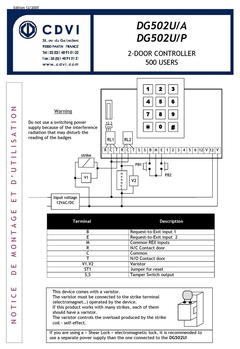
To protect the device from back EMF, do
not forget to install the varistor across
the lock terminals (in parallel).
This product is shipped with a
varistor.
The varistor must be connected directly
to the locking system terminals (electric
strikes, electromagnet, or lock) operated
by the device. If the device functions with
several locking systems, each one must
be tted with a varistor. The varistor limits
overload produced by the strike coil, known
as self-effect or back EMF. If you are using
a shearlock, electromagnet or other type
of electric lock, we recommend the use of
dedicated power supply for the lock.
For optimum
lighting, be
careful to not
fold the cable
inside the
product.
3] MOUNTING KIT
Leaktight
seal TF 3x30
Screws S5
Plastic anchor TORX®
Screwdriver tip TORX®3x8
Screws Varistor METALR tag
STAR1M 1 2 2 1 1 1 1
R
76,7
R
35,4
7
60
30
Ce document est la propritété exclusive de CDVI, il ne peut être communiqué à des tiers sans son autorisation.
This document is the exclusive property of CDVI and it may not be disclosed to others without permission.
31, av du Gal Leclerc
93691 PANTIN CEDEX
F R A N C E
Tel : 33(0)148910102
Fax
: 33(0)148912121
www.cdvi.com
Plan M1806-VdE
Edition 00
Date 01/10/2009
ECHELLE 1:1
A4V
DES.: A. Broustal
Matière : ...
Tolérance gale :
0.1
Etat de surface : Ra 3,2
A0228015
Badge PP New
plan coté pour dépôt "dessin&modèle"
C.A.: ...
Vol. (mm
3
)
:
Poids (g) :
IK09
Frequency band: 13,553 - 13,567 MHz
Maximum power emitted: 42 dBμA/m
We, CDVI, declare that the STAR1M complies with the 2014/53/UE European directive.
The full UE declaration is avaiblable on our website www.cdvi.com.
INSTALLATION MANUAL EN
Thank you for buying our products and for the trust placed in our company

cdvigroup.com 3
STAR1M - Mullion Mifare® standalone controller and card reader
INSTALLATION MANUAL EN
4] OPERATION MODES
Dipswitch Standalone mode
(page 13) Wiegand mode
(page 18)
1OFF ON
2
OFF ON OFF ON
Change the
Master card NORMAL
operation Dipswitch 3
option 44-bit
3
OFF ON OFF ON
Shadow mode
(page 15) Standard mode
(page 16) 26-bit 30-bit
4Not assigned
The different dipswitch positions are used to switch the STAR1M to a
standalone system or to a Mifare®access reader.
5] WIRING DIAGRAM
C56
C58
C61
1
MM10
4
3
2
1
ON
ON
ON
ON
L7
Q6
Q7
Q8
R77
R78
R79
P1
1P3
BZ3
C6
C24
C59
-
+
MM1
MM14
CR3
+
-
CR10
CR25
CR26
CR24
MM3
MM15
CR12
CR13
CR15
I1
+
-
+
-
MM16
CR22
P2
-
+
CR19
CR21
CR20
CR28
CR27
CR29
CR11
R70
R67
R68
R64
R69
R65
C68
CR30
Wire
colors
Wiring table
Standalone mode Wiegand mode
Red 12Vdc 12Vdc
Black 0V 0V
Green /Data 0
White /Data 1
Blue Normally open /
Grey Common /
Purple Normally closed /
Brown Request to exit input Buzzer input
Yellow /Green LED input
Orange /Red LED input
LEDs on start-up:
- Green (1s)
- Red (1s)
- Blue + BEEP (1s)
LEDs during routine operation:
- Standby: Blue
- When a tag is read: Green or red
To switch operation mode, please reboot the STAR1M.

cdvigroup.com
4
STAR1M - Mullion Mifare® standalone controller and card reader
6] SETTING READER MODE
1
ON
2
ON
3
ON
ON ON ON
1 2 3
ON
OFF
ON
OFF
Before powering on, select the operating mode (Wiegand Mifare®reader or
standalone mode).
1] Wiegand Mifare®reader (DIP1 ON)
- green
- red
- blue + buzzer (starting sequence)
2] Standalone mode (DIP1 OFF) = factory default setting
- green
- red
- blue + buzzer (starting sequence)
- yellow/green: waiting for the Master card to be programmed
(when powering on for the 1st time)
7] STANDALONE MODE
- Mifare®compliant - ISO 14443A (Mifare®classic)
- Programming using the Master card directly on the reader
- Capacity: 1 Master card + 300 or 150 user cards (according to mode)
- 1 door controller: 1 relay output N.O/N.C contact (1A 12Vdc)
- 1 request to exit input
- Compatible with METAL, PVP (Mifare®) badges, BV cards (ISO Mifare®
credit card format) and ERV, ERNV remote transmitters
INSTALLATION MANUAL EN
ON
4
ON
4
Electric strike wiring example (Fail secure)
12V DC
ADC335
Push button
Strike fail secure
All our locks are tted with a varistor.

cdvigroup.com 5
STAR1M - Mullion Mifare® standalone controller and card reader
INSTALLATION MANUAL EN
Electromagnetic lock wiring example (Fail safe)
12V DC
ADC335
Push button
Magnet
Strike fail safe
Normal operation
1
ON
2
ON
3
ON
4
ON ON
OFF
Swipe user card
Access granted
Beep + green LED + relay activated
Access denied
Beep + red LED
Blue LED
Position DIP2 to ON
The factory setting of the STAR1M is shadow mode.
For rst use, please program a master badge (see process page 8).

cdvigroup.com
6
STAR1M - Mullion Mifare® standalone controller and card reader
INSTALLATION MANUAL EN
Enter programming mode
Yellow led
Present user card
Beep + green LED then yellow LED Blue LED
Present the master badge
Swipe the master badge or
wait 10 seconds
Exit programming mode
To add more cards, repeat step user card
and step shadow card.
Present the shadow card
2 beeps + green LED ashing
Add user cards (max. 150)
Delete user cards
Enter programming mode
Yellow LED
Present the user card or its shadow card
Beep + LED OFF then back to yellow LED
Present again the same card
Beep + red LED then back to yellow LED
Both cards are deleted
Blue LED
Present the master badge
Swipe the master badge or
wait 10 seconds
Exit programming mode
7.1 Shadow mode
In Shadow mode, two different badges are programmed for the same user. The user
gets one of the two badges and the second badge is stored in a secure place by the
system supervisor as a shadow badge. These 2 badges can both grant access. In the
event that the user badge is lost or stolen, the shadow badge can be used to delete the
user badge from the STAR1M.
1
ON
2
ON
3
ON
4
ON ON
OFF
Dipswitch setting

cdvigroup.com 7
STAR1M - Mullion Mifare® standalone controller and card reader
Blue LED
INSTALLATION MANUAL EN
Add user cards (max. 300)
Enter programming mode
Yellow LED
Present the user card one after the other
Beep + green LED then yellow LED
If the card is already programmed
Beep + LED OFF then back to yellow LED
Blue LED
Present the master badge
Swipe the master badge or
wait 10 seconds
Exit programming mode
Enter programming mode
Yellow LED
Present the user card
Beep + LED OFF then back to yellow LED
Present again the same card
Beep + red LED then back to yellow LED.
Blue LED
Delete user cards
Present the master badge
Swipe the master card or
wait 10 seconds
Exit programming mode
7.2 Standard mode
In Standard Mode only one user badge is programmed for each user. To delete a user
from the STAR1M, enter the programming mode and present the user badge.
1
ON
2
ON
3
ON
4
ON ON
OFF
Dipswitch setting

cdvigroup.com
8
STAR1M - Mullion Mifare® standalone controller and card reader
INSTALLATION MANUAL EN
7.3 Common operation
Program or replace a Master badge
1
ON
2
ON
3
ON
4
ON ON
OFF
Set DIP2 to OFF
Yellow LED
+ Beep
Present the new master badge
(the old one will be erased)
Beep + LED OFF
1
ON
2
ON
3
ON
4
ON ON
OFF
Set DIP2 to ON
Beep
Blue LED
After 10 seconds
White and Red LED ashing
+ Beep
1 ash : 1 second
Program the unlock time
Enter programming
mode
Yellow LED
Press the push button
Each push button press: 1 second Blue LED
Present the master badge
Default value : 5 seconds, programmable from 01 to 99 seconds
1
ON
2
ON
3
ON
4
ON ON
OFF
Switch on power
supply
White/Red LED ashing while the
memory is deleted.
Followed by start-up sequence
Delete all cards (reset the reader to the factory
default values)
Switch off power supply
Set DIP1 to ON
Switch off power
supply
1
ON
2
ON
3
ON
4
ON ON
OFF
Set DIP1 and DIP2 to OFF
Standalone Mode is activated
Switch on power supply
To delete all cards switch to Wiegand mode Switch to standalone mode

cdvigroup.com 9
STAR1M - Mullion Mifare® standalone controller and card reader
INSTALLATION MANUAL EN
8.1 Wiegand 26, 30 and 44 bit output format
8] MIFARE® READER WIEGAND MODE
OFF
1
ON
2
ON
3
ON
4
ON ON
OFF
1
ON
2
ON
3
ON
4
ON ON
OFF
1
ON
2
ON
3
ON
4
ON ON
30-bit Wiegand Output
44-bit Wiegand Output
26-bit Wiegand Output
Important :
- Switching « shadow mode » to « independent mode »: all cards are saved
but become independant
- Switching « independent mode » to « shadow mode »: all cards are erased

cdvigroup.com
10
STAR1M - Mullion Mifare® standalone controller and card reader
INSTALLATION MANUAL EN
8.3 LEDs management in CENTAUR
8.2 LEDs management in ATRIUM
GREEN ACCESS GRANTED
RED ACCESS DENIED
BLUE STANDBY
LED STATUS
GREEN ACCESS GRANTED
RED ACCESS DENIED
BLUE STANDBY
LED STATUS
GREEN LED
CONFIGURATION
RED LED
CONFIGURATION
GREEN LED
CONFIGURATION
RED LED
CONFIGURATION
Reference : G0301FR1031V04
Extranet : CDVI_IM_STAR1M_A5_EN-01

cdvigroup.com 11
STAR1M - Mullion Mifare® standalone controller and card reader
Security to Access
www.cdvigroup.com
Reference : G0301FR1031V04
Extranet : CDVI_IM_STAR1M_A5_EN-01
*G0301FR1031V04*
CDVI Group
FRANCE (Headquarters)
Phone: +33 (0)1 48 91 01 02
CDVI FRANCE + EXPORT
31, av. du Général Leclerc
93500 PANTIN - France
Phone: +33 (0)1 48 91 01 02
www.cdvi.com
CDVI AMERICAS
[CANADA - USA]
Phone: +1 (450) 682 7945
www.cdvi.ca
CDVI BENELUX
[BELGIUM - NETHERLANDS - LUXEMBOURG]
Phone: +32 (0) 56 73 93 00
www.cdvibenelux.com
CDVI TAIWAN
Phone: +886 (0)42471 2188
www.cdvichina.cn
CDVI SUISSE
Phone: +41 (0)21 882 18 41
www.cdvi.ch
CDVI CHINA
Phone: +86 (0)10 84606132/82
www.cdvichina.cn
CDVI IBÉRICA
[SPAIN - PORTUGAL]
Phone: +34 (0)935 390 966
www.cdviberica.com
CDVI ITALIA
Phone: +39 0321 90 573
www.cdvi.it
CDVI MAROC
Phone: +212 (0)5 22 48 09 40
www.cdvi.ma
CDVI NORDICS
[SWEDEN - DENMARK - NORWAY - FINLAND]
Phone: +46 (0)31 760 19 30
www.cdvi.se
CDVI UK
[UNITED KINGDOM - IRELAND]
Phone: +44 (0)1628 531300
www.cdvi.co.uk
CDVI POLSKA
Phone +48 12 659 23 44
www.cdvi.com.pl
All the information contained within this document (pictures, drawings, features, specications and dimensions)
could be perceptibly different and can be changed without prior notice.
Other manuals for STAR1M
2
Table of contents
Other CDVI Controllers manuals

CDVI
CDVI ATRIUM A22K User manual

CDVI
CDVI ATRIUM AC22 User manual

CDVI
CDVI ATRIUM A22POE User manual

CDVI
CDVI ATRIUM A22K User manual

CDVI
CDVI SASIC User manual

CDVI
CDVI PROMI1000PC User manual

CDVI
CDVI DG502U/A User manual

CDVI
CDVI ATRIUM A22K User manual

CDVI
CDVI Digicode Mifare DGM1D User manual

CDVI
CDVI ATRIUM A22K User manual