SPEWE 112GT-28 User manual
1901180 / 08-2015 | spewe.ch
112GT / 112GTL
1
D
Glühdraht-Schneidegerät
Sicherheitshinweise / Daten 2
Bedienungsanleitung 3-10
Ersatzteilliste 11
F
Découpeuse a filament chauffant
Information / Instructions de sécurité 2
Mode d’emploi type 3-9
Liste pièces de rechange 10/11
I
Trancia a filo incandescente
Avvisi di sicurezza / Dati 2
Istruzioni per l’uso modello 3-9
Elenco dei pezzi di ricambio 10/11
GB
Heated Wire Cutting Device
Safety Instructions / Details 2
Operating Instructions 3-9
Replacement Parts 10/11
112GT-28
Mod. 2012
Art.-Nr. 1000006 (EU)
Art.-Nr. 1000107 (CH)
112GTL-28
Mod. 2013
Art.-Nr. 1000061 (EU)
Art.-Nr. 1000108 (CH)

2
112GT / 112GTL
1901183 / 08-2015
D
Sicherheitshinweise – Vorwort: Diese Anleitung ist die Grundlage zur Bedienung des Glühdraht-
Schneidegeräts. Sie verdient Ihre volle Aufmerksamkeit.
Bevor Sie mit irgendwelchen Arbeiten an oder mit dem Gerät beginnen, verpflichten wir Sie, die vorliegende An-
leitung und die separaten Sicherheitsbestimmungen bis zum Schluss sorgfältig durchzulesen. Bestehen irgend-
welche Unklarheiten, sprechen Sie uns umgehend dazu an. Nehmen Sie das Gerät nicht in Betrieb solange Un-
klarheiten bestehen. Mit der Inbetriebnahme des Gerätes bestätigen Sie, dass Sie die Anleitung gelesen und
verstanden haben und somit die Betriebsverantwortung übernommen haben.
Lieferumfang: Glühdraht-Schneidegerät 112GT/GTL-28 mit integriertem Trafo, Ersatzdraht,
Ersatzsicherung, Anleitung
Technische Daten: Schnittlänge: 110/127 cm | Schnitttiefe: 28.5 cm | Zuschnitt: Thermisch |
Stromversorgung: 230V/50Hz
F
Remarques de sécurité concernant les coupeuses à filament incandescent – Préface
Ce mode d’emploi est la base pour le maniement de la coupeuse à filament incandescent. Veuillez le consulter
avec beaucoup d’attention.
Avant de commencer quelques travaux que ce soit ou avant d’utiliser la coupeuse, nous vous engageons à lire
le présent mode d’emploi et les remarques de sécurité séparé a minutieusement jusqu’à la fin. S’il y a quelques
confusions, n’hésitez pas à nous contacter immédiatement. Ne mettez pas la coupeuse en service tant qu’il y a
des confusions. Avec la mise en service de la coupeuse, vous confirmez que vous avez lu le mode d’emploi et
que vous l’avez compris et ainsi vous prenez en charge la responsabilité du bon fonctionnement.
Fourniture : Coupeuse à filament incandescent type 112GT/GTL-28 avec transforma
teur intégré, filament de rechange, fusible de rechange, mode d'emploi.
Caractéristiques Longueur de coupe: 110/127 cm | Profondeur de coupe: 28.5 cm |
techniques: Découpe: thermique | Alimentation électrique: 230V/50Hz
I
Avvisi di sicurezza per la trancia a filo incandescente - Premssa
Le presenti istruzioni sono la base per l’uso della taglierina a filo incandescente.
Prima di iniziare qualsiasi operazione sull’apparecchio o con l’apparecchio, vi chiediamo di impegnarvi a leggere
attentamente le presenti istruzioni e la avvertenze di sicurezza separato fino alla fine. Qualora dovessero esser-
vi dei punti non chiari, contattateci immediatamente e parlatecene. Non mettete in funzione l’apparecchio fino a
quando sussistono questi dubbi. Mettendo in funzione l’apparecchio, confermate di avere letto le istruzioni e di
esservi assunto la responsabilità del relativo esercizio.
Corredo di fornitura : Apparecchio di taglio a filo incandescente tipo 112GT/GTL-28 con trasformatore
integrato, filo di ricambio, fusibile di ricambio, istruzioni per l’uso.
Dati tecnici: Lunghezza di taglio: 110/127 cm | Profondità di taglio: 28.5 cm | Taglio: termico |
Alimentazione: 230V/50Hz
GB
Hot wire cutter safety advice and instructions manual - Foreword
These instructions must be read before using the hot wire cutter. Please read them carefully.
Before you begin any work or begin using the tool, you must carefully read this introduction and the separate
safety advice . If you have any queries, please do not hesitate to contact us. Do not use the tool if you continue
to be unsure about any aspect. When you begin to use the tool, you tacitly confirm that you have read and un-
derstood the introduction and that you take full responsibility for the operation of the tool.
Scope of delivery: Hot-wire cutting tool Type 112GT/GTL-28 with integrated transformer, re
placement conductor, replacement fuse, operating instructions.
Technical details: Cutting length: 110/127 cm | Cutting depth: 28.5 cm | Cut: Thermal |
Power supply: 230V/50Hz
D
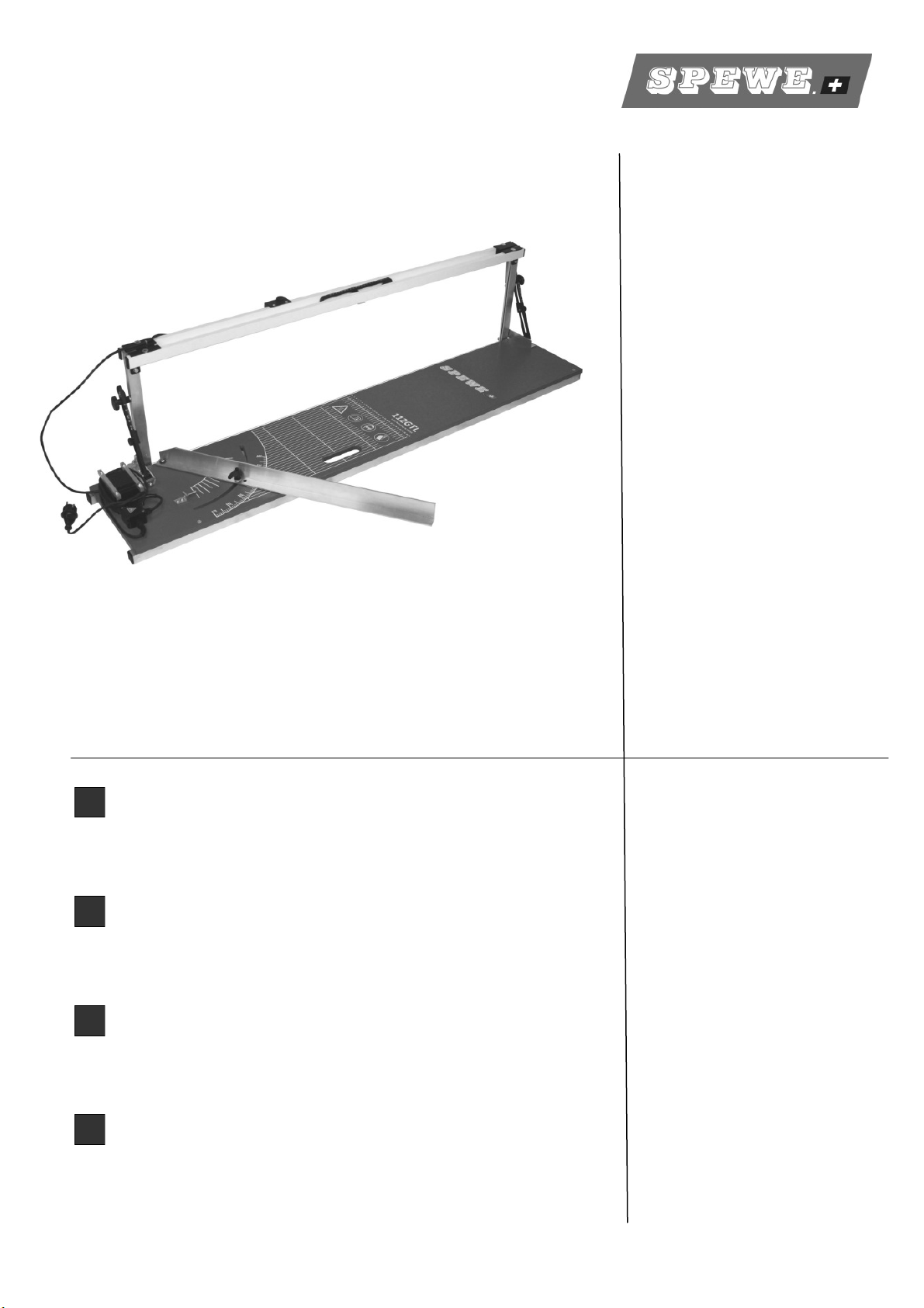
Ziehen Sie das Gerät an der Griffmulde aus der
Verpackung und nicht an den Bügelstreben.
Fig. 1
1901180 / 08-2015 |
112GT / 112GTL
3
Inbetriebnahme | Installation | Messa in funzione | Setting the Device Up
Fig. 2
2
1
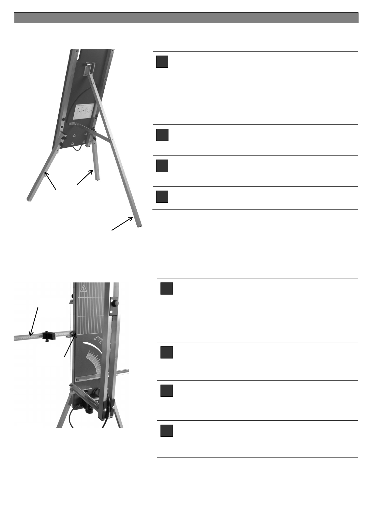
D
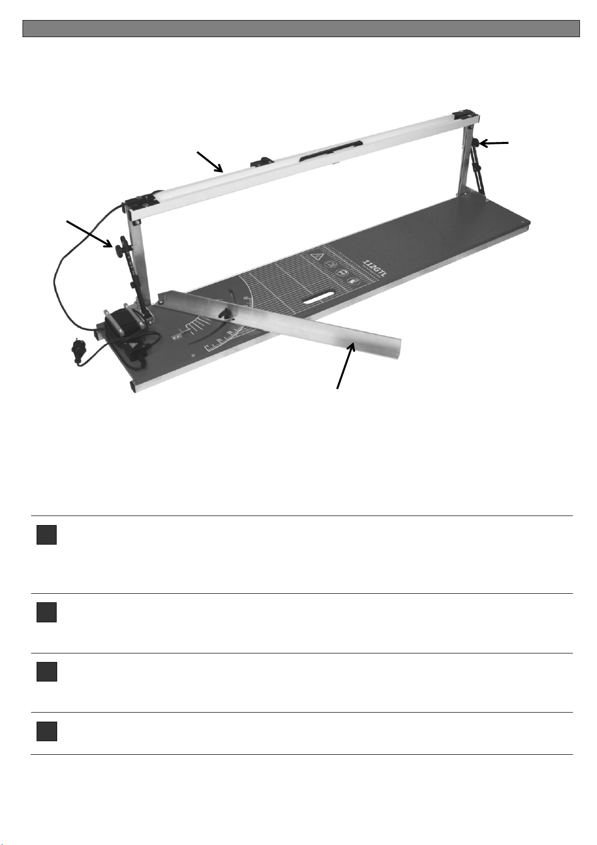
Gerät auf einen Tisch, einen Plattenbund oder auf Arbeitsböcke legen.
Sterngriffe [1] beidseitig lösen, Schneidbügel [2] aufklappen und Sterngriffe [1] wieder fixieren.
Klemmhebel an Auflageschiene (3) lösen, Auflageschiene abschwenken und Klemmhebel wieder
leicht fixieren. Netzkabel abwickeln und an 230V Netz anschliessen.
F
Dévissez les poignées en étoile [1] en haut et en bas, dépliez l’étrier de coupe [2] et resserrez les
poignées en étoile [1]. Dépliez le rails de support [3].
Déroulez le câble de raccordement au réseau et raccordez le au 230V.
I
Allentare l’impugnatura a stella [1] superiore e inferiore, ribaltare l’archetto da taglio [2] e fissare le
impugnature a stella [1]. Oscillare le guide di supporto [3] verso il basso.
Cavo di alimentazione e collegarlo a gestire il potere 230V.
GB
Release star knob [1] at bottom and top, fold back cutting bow [2] and fixate star knob [1]. Pull out
bearing rail [3]. Unravel power cable and connect to 230V power outlet.
1
3

4
112GT / 112GTL
1901183 / 08-2015
Schnittvarianten | Variantes de coupes | Varianti di taglio | Cutting variants
4
5
7
7
6
1
1
Fig. 3

1901180 / 08-2015 |
112GT / 112GTL
5
Schnittvarianten | Variantes de coupes | Varianti di taglio | Cutting variants
D
Dämmplatte auf Gerät legen. Schneidbügel [4] hochziehen, Dämmplatte bis zum gewünschten
Zuschnittmass vorschieben, Drucktaster [5] betätigen und Schneidbügel durch Dämmplatte
drücken. ! Der Trafo ist nicht für Dauerbetrieb ausgelegt. Nach erfolgtem Schnitt muss der
Drucktaster wieder losgelassen werden.
Falzschnitt: Mittels schwenk- und in der Höhe einstellbarem Tiefenbegrenzer [6] können auch
Falz- oder Auftrennschnitte ausgeführt werden.
Gehrungsschnitt: Mittels beidseitiger Feststeller [7] können auch rasch wiederholbare
Gehrungsschnitte eingestellt werden.
F
Sortir l’étrier [4] avant la coupe, Pousser le panneau [5] jusqu’à la cote de coupe et laisser
l’étrier dans le panneau.
Le transformateur n'est pas conçu pour un fonctionnement continu.
Coupe de rainure : Poser la butée de profondeur [6]. Régler la profondeur de rainure ou
l’épaisseur de coupe . Poser le panneau isolant, Avancer le panneau jusqu’au marquage de
découpe voulu, Soulever l'étrier de découpe et découper le pli. Des panneaux complets peuvent
être découpés avec ce réglage.
Onglets : Transférer l’onglet sur le panneau isolant que vous placerez dans l‘appareil. Desser-
rer la poignée étoile inférieure [1], tourner l’étrier jusqu’à ce que l’onglet coïncide avec le
marquage sur le panneau et fixer la poignée étoile. Pousser le curseur [7] pour les coupes
répétitives, puis le pousser et le fixer par la poignée étoile.
I
Estrarre l’archetto [4] prima del taglio, premere il pannello fino [5] alla misura di taglio desiderata
e lasciare l’archetto nel pannello.
Il trasformatore non è progettato per un funzionamento continuo.
Taglio piegato: Posizionare il limitatore di profondità [6] in perpendicolare. Determinare una
profondità o spessore di scanalatura. Inserire il pannello isolante, far avanzare il pannello fino
alla marcatura di taglio desiderata, sollevare l’archetto per taglio e tagliare la piega. Con questo
sistema è anche possibile isolare interi pannelli.
Taglio ad angolo: Trasferire il taglio ad angolo sul pannello isolante e inserirlo nell’apparecchio.
Allentare l’impugnatura a stella [1], ruotare l’archetto per taglio fino a combaciare la marcatura
sul pannello isolante e fissare l’impugnatura a stella. Per l’esecuzione di tagli ad angolo ripetuti,
spostare e fissare il corsoio [7] nelle parti superiore e inferiore sull’impugnatura a stella
GB
Pull out bracket [4] before cutting, push board [5] forwards to cutting dimension and allow
bracket to dive into board.
The transformer is not designed for continuous operation.
Seam: Place depth limiter [6]. Set seam depth or separating thickness. Insert insulation board,
push the board forward to the cutting marking desired, lift the cutting bracket and cut out seam.
With this setting, entire boards can also be separated.
Mitre cut: Transfer mitre to insulation board and insert in equipment. Loosen star handle [1] at
the bottom, swerve cutting bracket until mitre matches the mitre on the insulation board and
secure star handle. For repeat cuts, push slide [7] at bottom on star handle and secure it.
6
112GT / 112GTL
1901183 / 08-2015
Justierung | Ajustage | Torsiometrica | Adjustment
Störungsursachen | Les problèmes potentiels | Potenziali problemi | Potential problems
D
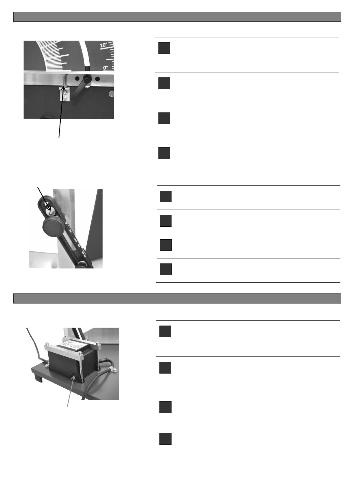
90°-Justierung:
Konterschraube [8] lösen, Schnittwinkel neu
ausrichten und Schraube wieder fixieren.
F
Ajustage à 90 ° :
Desserrez la vis [8], modifiez l'angle de coupe et
fixez de nouveau la vis.
I
Regolazione a 90°:
Allentare la vite [8] regolare l’angolo di taglio e
fissare nuovamente la vite.
GB
90°-alignment:
Loosen the screw [8], adjust the cutting angle again
and fix the screw again.
8
D
90°-Schnittwinkel kann mittels Reiter [9] exakt
nachjustiert werden.
F
Un angle de coupe de 90° peut être ajusté avec
précision au moyen du curseur [9].
I
L’archetto per taglio a 90° può essere nuovamente
regolato in modo esatto mediante il corsoio [9].
GB
90° cutting angles can be readjusted precisely with a
slide [9].
9
D
Sicherung ersetzen: Dreh- und Druckschraube [10]
für die Feinsicherung entfernen, defekte Sicherung
ersetzen und Schraube wieder eindrehen.
Feinsicherung 5x20mm
F
Remplacez le fusible: Retirez la vis rotative et à
pression [10] pour les fusibles fins, remplacez les
composants défectueux et repositionnez la vis.
Fusible 5x20mm
I
Sostituire il fusibile: girare e rimuovere la vite [10]
per fusibili fine, sostituire difettoso Si-assicurazione
e vite del bullone. Fusibili 5x20mm
GB
Replace fuse: turn and remove screw [10] for fine
fuses, replace defective Si-assurance and bolt
screw. Fuses 5x20mm
10
Fig. 4
Fig. 5
Fig. 6

1901180 / 08-2015 |
112GT / 112GTL
7
Draht ersetzen | Remplacer | Sostituzione e trazione del filo | Replacing
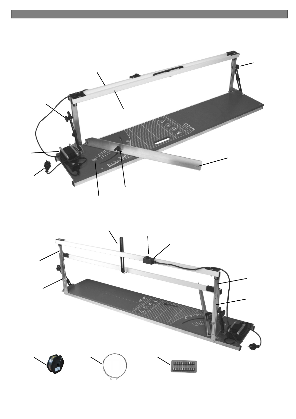
D
Draht ersetzen : Gerät vom 230V Netz trennen.
Bei einem Drahtriss den restlichen Draht vom Gerät
entfernen. Von der Ersatzdrahtspule ungefähr den
erforderlichen Draht ablösen.
Am einen Drahtende eine kleine Schlaufe bilden,
den Draht an der ersten Feder [11] einhängen, über
die erste [12] und zweite [13] Drahtführungsrolle bis
zur zweiten Zugfederöse [14] führen. Die zweite
Feder so stark spannen, dass beide Federn um ca.
3 cm länger werden. Danach den Draht einige Male
um sich selber wickeln (Schlaufe bilden) und restli-
chen Draht abklemmen.
Achten Sie beim Schneiden hin und wieder, dass
die Zugfedern jeweils genügend gespannt sind.
F
Remplacer / retendre le filament: Débrancher l’appareil du secteur 230V.
En cas de rupture de filament, enlevez le reste de fil de l’appareil. Dévidez la quantité approximative
de filament nécessaire de la bobine de rechange.
Faites une petite boucle à une extrémité [11], accrochez le filament au premier ressort [12], passez
le par le rouleau de guidage [13] jusqu’au deuxième [14], engagez le sur le deuxième anneau du
ressort de traction et commencer à tendre le 2
ème
ressort jusqu’à ce que les deux ressorts
s’allongent d’environ 3 cm. Puis enroulez le fil de plusieurs tours sur lui-même (boucle) et coincez le
reste de filament.
Assurez-vous de temps à autre lors de la coupe que les ressorts de traction sont toujours
suffisamment tendus.
I
Sostituzione e trazione del filo: Alimentare l’apparecchio a 230 V.
In caso di rottura del filo, rimuovere il filo residuo sull’apparecchio. Allentare il filo necessario dalla
bobina del filo di ricambio.
Realizzando un piccolo cappio [11] a un’estremità, il filo si aggancia alla prima molla [12], passa
attraverso il rullo guidafilo [13] fino al secondo [14], viene teso dal secondo anello della molla di
tensione e inizia a tendere la seconda molla tanto intensamente da allungare le due molle di circa 3
cm. Successivamente, avvolgere leggermente il filo su se stesso (cappio) e fissare il filo residuo.
Verificare saltuariamente mediante il taglio che le molle di tensionamento siano adeguata-
mente tese.
GB
Replacing, tightening wire: Disconnect equipment from 230V mains.
If a wire snaps, remove the remaining wire from the equipment. Cut off the approximately required
wire from the spare coil.
Make a small loop [11] at one end, connect the wire to the first spring [12], guide it via the wire-
guiding pulley [13] through to the second one [14], pull it through the second tension spring eye and
start to tighten the second spring so that both springs are extended by approx. 3 cm. Then wrap the
wire several times around itself (loop) and cut off the remaining wire.
When cutting, check occasionally that the tension spring is sufficiently tight.
11
12
13 14
Fig. 7
Fig. 8
8
112GT / 112GTL
1901183 / 08-2015
Optionales Zubehör* | Accessoires optionnels | Accessorio optional | Optional accessory
* Zubehör kann teilweise im Lieferumfang enthalten sein.
D
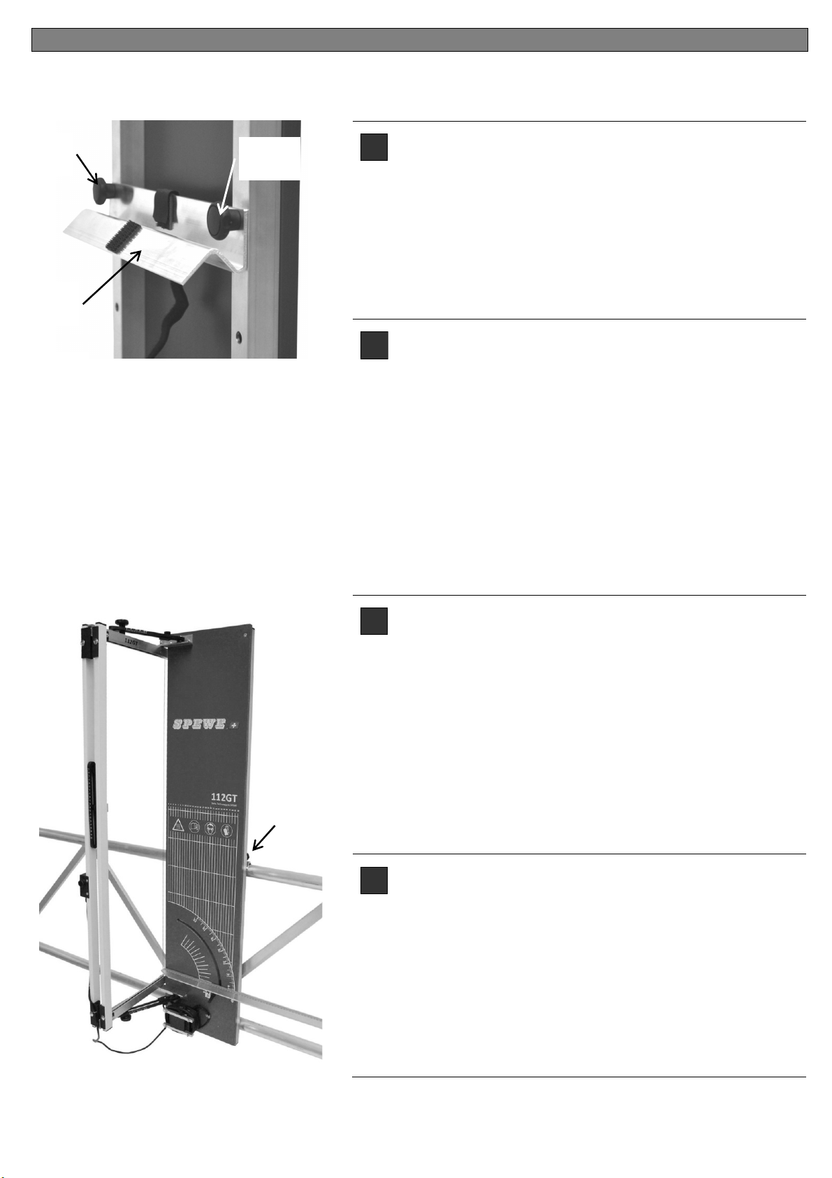
Geländerhalterung [15](Optional)
für senkrechten Geräteeinsatz am Rückengeländer.
Montage: Geländerhalterung an Rückseite des Ge-
rätes mittels beiliegenden Sterngriffschrauben [15a] in
die dafür vorgesehenen Gewindebüchsen montieren.
Gerät mittels Gerüsthalterung auf Geländerstange
setzen und Klettband um Geländerstange legen. Das
Gerät ist somit gegen ein Herunterfallen gesichert.
F
Support de balustrade [15] (Accessoires optionnels)
pour une utilisation de l'appareil en position verticale
sur la balustrade.
Montage: Montez le support de balustrade au dos de
l'appareil à l'aide des vis papillons mises à disposition
[15a] en les plaçant dans les filetages prévus à cet
effet.
Placez la coupeuse sur la barre de l'échafaudage
comme sur l'illustration.
Enroulez de la bande Klett autoagrippante autour de
la barre de la balustrade. C'est ainsi que l'appareil est
protégé contre les chutes.
I
Supporto per parapetto [15](Accessorio optional)
per l’uso dell’apparecchio in senso verticale su una
ringhiera posteriore.
Montaggio: Montare il supporto per parapetto sul lato
posteriore dell’apparecchio con le viti con manopola a
crociera [15°] nelle apposite bussole filettate.
Applicare l’apparecchio di taglio sulla barra del
parapetto secondo le modalità illustrate nella figura.
Avvolgere il nastro di velcro intorno alla barra del
parapetto per impedire che l’apparecchio possa
cadere.
GB
Scaffolding support [15](Optional accessory)
for vertical use of tools in the rear handrail.
Assembly: Mount the scaffolding support on the rear
of the Tool in the tapped bush meant for it with the aid
of the attached star handle screws [15a].
Put the cutting tool on the scaffolding rod as in the il-
lustration,
Put the Velcro strip around the scaffolding rod. The
tool is thus protected from falling down.
15a
Art.
-
Nr. 1
2
0
0
0
2
0
15a
15
15
Fig. 9
Fig. 10
1901180 / 08-2015 |
112GT / 112GTL
9
Optionales Zubehör* | Accessoires optionnels | Accessorio optional | Optional accessory
* Zubehör kann teilweise im Lieferumfang enthalten sein.
D
Fussstützen [16]Optionales Zubehör
Nachrüstsatz für Geräteeinsatz als Standgerät
Freistellstütze mit Strebe [16a]:Stütze und Streben-
winkel an vorgesehener Stelle mittels Schrauben
montieren. Stütze bleibt nach Montage am Gerät.
Einsatz: Stütze abschwenken und Strebe an Winkel
einhängen.
F
Support de balustrade [16] Accessoires optionnels
Kit de rattrapage pour utiliser l’équipoment tant qu‘unité
autonome
I
Poggiapiedi [16] accessorio opzionale
Kit di retrofit per le applicazioni del dispositivo come
unità stand-alone
GB
Footrests [16] optional accessory
Retrofit kit for device applications as standalone unit
D
Schwenkbare Skala mit Anschlagreiter [17]
(Optionales Zubehör)
Nachrüstsatz zur Montage an die linke Geräteseite
Montage:
Mittels Schraube [17a] in die dafür vorgesehen
Gewindebüchse an Geräterückseite befestigen.
F
Pivotant échelle avec butée réglable [17]
(Accessoire en option)
Kit de rattrapage pour le montage sur le côté gauche
de l'appareil
I
Girevole con scala arresto regolabile [17]
(Accessorio opzionale)
Retrofit kit per il montaggio sul lato sinistro del
dispositivo
GB
Pivoting scale with adjustable stop [17]
(Optional accessory)
Retrofit kit for mounting on the left side of the device
16a
Art.-Nr. 1200054
Art.
-
Nr. 1
20
00
2
2
17a
16
Art.-Nr. 1200021
17
Fig. 11
Fig. 12
10
112GT / 112GTL
1901183 / 08-2015
Ersatzteilliste | Nomenclature | Elenco parti di ricambio per modello | Spare parts list
112GT-28 ab Nr. 0381
112GTL-28 ab Nr. 0001
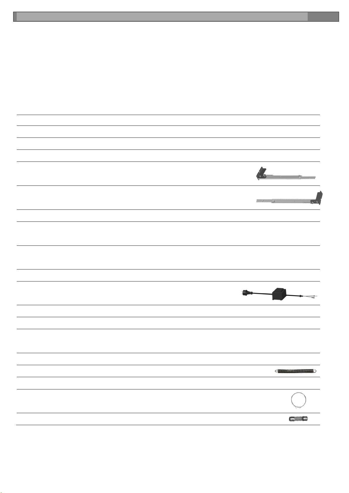
Nr. Art.-Nr. Beschreibung
1 1900198 Auflageschiene mit Klemmung
2 1900197 Klemmung Auflageschiene (mit Klemmhebel)
3 1901590 Justierung Auflageschiene kompl.
4
1900213
Kugelführung GT-28 / GTL-28 Oben komplett
5
1900214
Kugelführung GT-28 / GTL-28 Unten komplett
6 1900443 Befestigungskit (Sterngriff 40 mit Büchse)
7
1902748
1902935
Bügelstrebe Auszug GT RAL 9003, kompl. mit Schaltergehäuse
Bügelstrebe Auszug GTL RAL 9003, kompl. mit Schaltergehäuse
8
1902747
1902936
Bügelstrebe Fest GT, RAL 9003
Bügelstrebe Fest GTL, RAL 9003
9 1901597 Tiefenbegrenzer 28 mit Rändelschraube
10 1900611
Transformator 230V
11 1900224 Schaltergehäuse Links, kompl. mit Drucktaster
12 1900086 Drucktaster 10A, schwarz
13
1900068
1900067
Netzkabel DE/EU, mit Konturenstecker
Netzkabel CH, Flachstecker
14 1900475 Folien-Skala 0-100cm x12mm
15 1900521 Zugfeder 50mm
16 1200018 Ersatzdraht 0.65mm / 20 m
17
1200092
1200091
Schneiddraht 131 cm Ø 0,65mm, 5 St. (112GT-28)
Schneiddraht 149 cm Ø 0,65mm, 5 St. (112GTL-28)
18 1900084 Sicherung 5x20, 10 A, 10 Stk.
1901180 / 08-2015 |
112GT / 112GTL
11
Ersatzteilliste | Nomenclature | Elenco parti di ricambio per modello | Spare parts list
112GT-28 ab Nr. 0381
112GTL-28 ab Nr. 0001
1,14
2
3
9
5
6
6
7
8
4
10
11
12
13
15
15
16
18
17
Fig. 13
Fig. 14
This manual suits for next models
5
Other SPEWE Cutter manuals

SPEWE
SPEWE 1200169 User manual

SPEWE
SPEWE 1900L-30 User manual

SPEWE
SPEWE 3500EL-40 Manual

SPEWE
SPEWE Isoturbo 6000L S-05 User manual

SPEWE
SPEWE 112SL-28 User manual

SPEWE
SPEWE DT127-30 User manual

SPEWE
SPEWE 1900ML-30 04 Series User manual

SPEWE
SPEWE FD144T-30 User manual

SPEWE
SPEWE 212SL-30 User manual

SPEWE
SPEWE 112SL-28 Manual

SPEWE
SPEWE 410GTL 2014 User manual

SPEWE
SPEWE ES-212SL-30 User manual

SPEWE
SPEWE 890SL User manual

SPEWE
SPEWE 600SL User manual

SPEWE
SPEWE ES-5305 Series User manual

SPEWE
SPEWE 1900M-24 User manual

SPEWE
SPEWE ES-5300 User manual

SPEWE
SPEWE 5300S User manual

SPEWE
SPEWE 791GT User manual

SPEWE
SPEWE DT104-28 User manual


