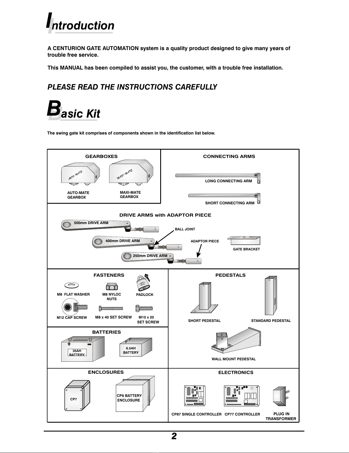
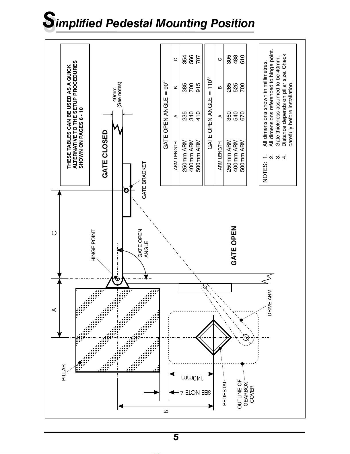
Centurion Auto-Mate User manual
Other Centurion Gate Opener manuals

Centurion
Centurion VECTOR2 User manual

Centurion
Centurion Auto-Mate User manual

Centurion
Centurion D10 User manual

Centurion
Centurion R3 User manual

Centurion
Centurion D2 Turbo User manual

Centurion
Centurion VECTOR2 User manual

Centurion
Centurion D5-EVO REPAIR User manual

Centurion
Centurion R3R5 User manual

Centurion
Centurion R3 User manual

Centurion
Centurion D10 User manual

Centurion
Centurion A10 Series User manual

Centurion
Centurion LEVER4 User manual

Centurion
Centurion D10 User manual

Centurion
Centurion CP70R5 User manual

Centurion
Centurion Vector User manual

Centurion
Centurion D5-EVO REPAIR Owner's manual

Centurion
Centurion A10 Series User manual

Centurion
Centurion D2 Turbo User manual

Centurion
Centurion D2 Turbo User manual

Centurion
Centurion R3 Specification sheet