manuals.online logo
Brands
  1. Home
  2. •
  3. Brands
  4. •
  5. Jamara
  6. •
  7. Transmitter
  8. •
  9. Jamara SCX User manual

Jamara SCX User manual

IT - Istruzioni per l’uso
GB - Instruction
SCX 2,4 GHz
Trasmittente | Transmitter
No. 061172
44/20
IT - Indicazioni generali
L’azienda JAMARA e. K. non risponderà dei danni causati al prodotto o dal prodotto, qualora esse
derivino dall‘uso o dall‘utilizzo non conforme. Il cliente sarà pienamente responsabile del cor-
retto uso e del corretto utilizzo. Ciò riguarda, in particolare, il montaggio, il processo di ricarica,
l‘applicazione, la scelta dell‘area di applicazione. A tal ne sarà necessario prendere conoscenza
delle istruzioni per l’uso, contenenti informazioni e avvertenze importanti.
GB - General information
JAMARA e.K. is not liable for any damage caused to the product itself or by it, if this is due to impro-
per operation or handling errors. The customer alone bears the full responsibility for the proper use
and handling, including in particular, assembling, charging and using the model, and selecting the
area in which to use it. Please refer to the operating and user instructions, which contain important
information and warnings.
IT - Dichiarazione di conformità
Con la presente JAMARA e.K. dichiara che il prodotto “SCX 2,4 GHz, No. 061172“ è
conforme alla Direttiva 2014/53/UE, 2011/65/UE.
Il testo integrale della dichiarazione di conformità UE è disponibile al seguente indiriz-
zo Internet: www.jamara-shop.com/Conformity
GB - Certicate of Conformity
Hereby JAMARA e.K. declares that the product “SCX 2,4 GHz, No. 061172“ complies with Directive
2014/53/EU, 2011/65/EU.
The full text of the EU Declaration of Conformity is available at the following Internet address:
www.jamara-shop.com/Conformity
Contenuto del kit:
• Trasmittente
• Ricevente
• Istruzioni
Accessori richiesti:
8 x batterie AA Cod. 140267 (4 pz.)
Highlights:
• Trasmittente 2 canali 2,4 GHz
• Ricevente 3 canali 2,4 GHz
• 2 interruttori per Reverse
• 2 Trim
Dati tecnici:
Frequenza 2,4 GHz
Modulazione GFSK
Modulazione servo 10 Bit (1024 Passi)
Adatto per Auto, Barche
Canali 2 Servo/Reverse
Temperature - 15 bis + 58° C
Tensione di operazione 12 V DC (8 Celle)
Caricamento batterie Presa incorporata
Misure ~ 190 x 210 x 81
Peso ~ 700 g
Ricevente SCX 2,4 GHz
Cod. 06 1171
Dati tecnici:
Frequenza 2,4 GHz
Modulazione GFSK
Modulazione servo 10 Bit (1024 Passi)
Tensione di operazione 4,5 - 7,4 V DC
Misure ~ 38 x 22 x 13 mm
Peso ~ 11 g
Portata ~ 400 m
Box contents:
• Transmitter
• Receiver
• Instruction
Recommended Accessories
8 x AA Batteries Ord. No. 140267 (4 pieces)
Features:
• 2 Channel 2,4 GHz Tranmitter
• 3 Channel 2,4 GHz Receiver
• 2 Servo Reverse
• 2 Trim Sliders
• Charging socket
• Programmable fail-safe on the receiver
Technical data:
Frequency 2,4 GHz
Modulation GFSK
Servo resolution 10 Bit (1024 Steps)
Model types Car, boat
Functions 2 channel
Temperature range - 15 to + 58° C
Receiver antenna length ~ 26 cm
Operating voltage 12 V DC (8 cells)
Charging Via charging socket
Size ~ 190 x 210 x 81 mm
Weight ~ 700 g
Receiver SCX 2,4 GHz:
Ord.No. 06 1171
Technical data:
Frequency 2,4 GHz
Modulation GFSK
Servo resolution 10 Bit (1024 steps)
Operating voltage 4,5 - 7,4 V DC
Size ~ 38 x 22 x 13 mm
Weight ~ 11 g
Range: ~ 400 m
Questo modello non é un giocattolo!
Prima di avviare il modello, leggere attentamente tutte le istruzioni per l’uso.
Attenzione! Leggere completamente le avvertenze / istruzioni di sicurezza,
questi sono per la vostra sicurezza può prevenire incidenti / infortuni.
For model building only - Not a toy!
Read the complete instructions and security instructions carefully before using the
model.
Caution! Please fully and carefully read warnings/ safety instructions.
These are for our own security and can avoid accidents/injuries.
Rispettate inoltre le norme seguenti:
• Prima di accendere la vostra radio controllate che lo stick del gas sia al minimot.
• Assicurarsi che il binding della trasmittente e della ricevente siano effettuati in modo corretto.
• Accendete primable trasmittente e poi la ricevente.
• Agite al contrario per spegnere.
• Prima di andare in volo fate sempre una prova di portata in distanza con il modello a terra e
l‘antenna chiusa.
• Non mettere in pericolo persone o animali.
• Utilizzare il sistema o il modello solo per essere controllati su un terreno adatto.
• Non usare la trasmittente con pioggia, vento forte oppure temporali.
• Se per un periodo più lungo non usata la trasmittente, togliete le batterie.
Following should be strictly adhered to:
• Before Switching on the system ensure that throttle stick is in the off position.
• Check that the transmitter and receiver are compatible and bonded to one another.
• Always switch the transmitter on rst and then the receiver.
• Always switch the receiver off rst and then the transmitter .
• Complete a full range and function test before every take-off .
• Never over-y people and do not allow your model to endanger people or animals.
• Do not y near to over-head cables, buildings or airelds.
• The system must not be operated in rain, or thunder storms.
• If you do not intend to use the transmitter for a long period, remove the batteries.
Frequency bands: 2.4 GHz Frequency range: 2405,5 – 2475,0 Mhz EIRP: < 5 mW (max. power transmitted)
2
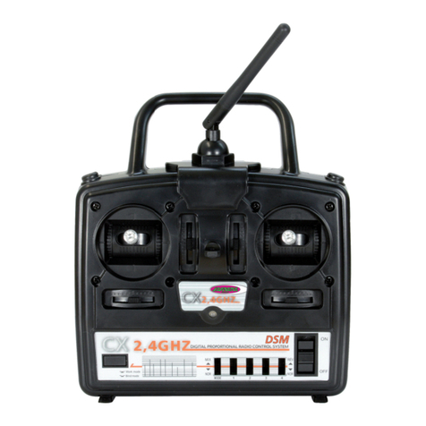
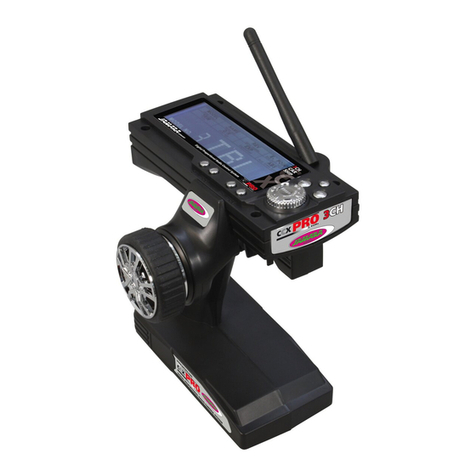
DE - Trasmittente
1 Antenna
2 Maniglia
3 Power LED
4 Servo Reverse CH 1
5 Stick controllo
6 Controllo trim
7 Tasto di collegamento
8 Interruttore On/Off
9 Stick gas
10 Gas trim
11 Servo Reverse CH 2
12 Indicatore LED
Alloggiamento batterie
Troverete questo scomparto sul retro della
vostra radio; per aprirlo spingete il coperchio
della direzione “PUSH”. Montando le batterie
ispettate la polarità indicata.
Ricevente
La ricevente offre collegamenti diretti per un
massimo di due servi.
Attribuzione uscite della ricevente:
Canale 1: Direttivo
Canale 2: Gas
Bind/Canale 3: Cavo di sincronizzazione
Receiver
2 Servos can be connected directly to the re-
ceiver.
Receiver Channel Allocation:
Channel 1: Steering
Channel 2: Throttle
Binding Channel 3: Binding Cable
GB - Transmitter
1 Antenna
2 Handle
3 Power LED
4 Servo Reverse CH 1
5 Left/Right Stick
6 Left/Right Trim
7 Binding Button
8 ON/OFF Switch
9 Throttle Stick
10 Throttle Trim
11 Servo Reverse CH 2
12 Indicator LED
Battery Hatch
The battery hatch is located on the rear side
of the transmitter and to open it simply push
down on the position marked ‚Push‘ and slide
the cover away. When tting the batteries al-
ways be very careful not to short circuit them
by observing the correct polarity.
Procedura di sincromizzazione
Su tutte le radio in banda 2.4 GHz é necessario che ad ogni accensione la trasmittente si sincronizzi
con la ricevente afnché le due possano comunicare fra loro. Questa operazione è necessaria
poiché, se non eseguita questa procedura nel modo corretto, la vostra radio no funzionerà. Proce-
dete perciò come vi indichiamo qui di seguito:
1. Collegare il cavo alla ricente sul canale 3. Poi alimentare la ricevente con il voltaggio. Il indicatore
LED alla ricevente BAT lampeggia.
2. Premete il pulsante di sincronizzazione del trasmettitore ed accendetelo. In questo modo entrate
nella modalità di sincronizzazione.
3. Quando questa operazione è stata fatta con successo, il LED si luci.
4. Spegnete sia la Trasmittente che la Ricevente.
5. Scollegate il cavo di collegamento della Ricevente.
NOTA IMPORTANTE
Il radiocomando non funziona se il commutatore di sincronizzazione è attivato. Controllate inoltre
che la Trasmittente non resti accesa a lungo in modalità sincronizzazione.
Binding
As with all 2,4 GHz systems the transmitter and the receiver must be bound together and this process is
vital. Before the system is bound together it will not function and therefore cannot be used and so the
following steps must be followed before you attempt to operate the system:
1. Fit the binding plug to socket 3 on the receiver and connect the power supply.
The receiver LED will begin to blink:
2. Press and hold down the binding button on the transmitter and switch the power on.
This will put the transmitter into binding mode.
3. Once the binding process has finished the LED will shine.
4. Switch the transmitter and receiver off.
5. Remove the binding plug.
Important Information
The system will not function whilst the binding button is pressed. Also, the system should not be left in
binding mode for long periods of time.
Regolazioni
Prima di collaudare in volo il vostro modello, controllate il buon funzionamento ed il corretto senso di
rotazione dei servocomandi. Vericato questo, montate tutte le squadrette sui servi delle parti mobili
in posizione neutra la squadretta del comando gas con lo stick al minimo a carburatore chiuso.
Settings
Before you operate your model carefully check that the servo operate in the correct direction.
If they do not rotate in the correct direction use the servo reverse switches located on the front of
the transmitter to change the direction. The servo neutral positions should then be set by moving the
servo arms until they are at exactly 900 with the trim central. The trim should only be used to make
ne adjustments when operating the model. If you are using this system with an Internal Combus-
tion engine make sure that the linkage cannot bind in either the full throttle or tick-over positions.
Procedure di accensione
1. Mettere insieme tutti gli elementi.
2. Accendere la trasmittente.
3. Collegare la batteria alla ricevente.
4. Vericare che il led sul ricevitore sia stabilmente acceso.
5. Il sistema è acceso e può essere utilizzato.
Switching On
1. Connect all of the components together.
2. Switch ion the transmitter.
3. Connect the power supply to the receiver and switch on if required.
4. Check that all of the LEDs are correctly illuminated.
5. The system is now switched on and ready to operate.
Sequenza di spegnimento
1. Disinserire la batteria dalla ricevente
2. Spegnere la trasmittente
Switching Off
1. Switch off and unplug the receiver power supply.
2. Switch off the transmitter.
12
11
10
9
8
1
2
3
7
4
5
6
33
Direzione:
Con questa funzione viene effetuata la direzione. Mentre si muovono stick a destra o sinistra, le
ruote assale anteriore o/e timone della fusoliera barca devono muoversi nella direzione relativa.
Steering
This function is used to steer the model in the correct direction. Moving the steering stick to the left
or right will make the wheels, or hull if operating a boat, move in that direction. Moving the stick to
the left should make the model steer to the left.
IT - Controllo del modello GB - Operating The Model
Controllo del gas
Con questa funzione viene pilotato il controllo anteriore e retro, come la verlocità. Qundo si preme
il stick in avanti, il modello va in avanti. Se si preme il stick in dietro, il modello prima frena e poi si
muove nel indietro.
Throttle
This function is used to make the model move forward or in revers and it also is used to control the
model‘s speed. Pushing the stick forwards makes the model accelerate forwards and pulling it to
the rear will make the model brake rst and then to accelerate in reverse.
Istruzioni per lo smaltimento
Apparecchi elettrici non devono essere smaltiti nei riuti domestici, ma devono essere
smaltiti separatamente. Siete obbligati di rimuovere le batterie e portare l´apparecchi
elettrici vecchi ai punti di raccolta comunali. Qualora ci sono dati personali sul apparec-
chio elettrico, devono essere rimossi da voi stessi.
Disposal restrictions
Electrical appliances must not be disposed of in domestic waste and must be disposed of separately.
You are obliged to take out the batteries, if possible, and to dispose of the electrical equipment at
the communal collection points. Should personal data be stored on the electrical appliance you must
remove them by yourself.
Reitter Modellbau Versand
Patricia Reitter
Degerfeldstrasse 11
72461 Albstadt
Tel 07432 9802700
Fax 07432 2009594
Mail [email protected]
Web www.modellbauversand.de
PenTec s.r.o.
distributor Jamara for Czech Republic and Slovakia
Veleslavínská 30/19
CZ -162 00 Praha 6
Tel +420 235 364 664
Mobil. +420 739 075 380
Mail servis@topdrony.cz
Web www.topdrony.cz
DE
Bay-Tec
Martin Schaaf
Am Bahndamm 6
86650 Wemding
Tel 07151 5002192
Fax 07151 5002193
Mail [email protected]
Web www.bay-tec.de DE
JAMARA e.K.
Manuel Natterer
Am Lauerbühl 5
DE-88317 Aichstetten
Tel +49 (0) 75 65/94 12-0
Fax +49 (0) 75 65/94 12-23
Mail [email protected]
Web www.jamara.com EU CZ
IT - Centro assistenza GB - Service centre
Modellbau Zentral
Peter Hofer
Bresteneggstrasse 2
CH-6460 Altdorf
Tel +41 79 429 62 25
Mobil. +41 41 870 02 13
Mail [email protected]
Web www.modellbau-zentral.ch CH
JAMARA e.K.
Inh. Manuel Natterer
Am Lauerbühl 5 - DE-88317 Aichstetten
Tel. +49 (0) 75 65/94 12-0 - Fax +49 (0) 75 65/94 12-23
[email protected] ●www.jamara.com
Service - Tel. +49 (0) 75 65/94 12-777
kundenservice@ jamara.com
Irrtum und technische Änderungen vorbehalten. Copyright JAMARA e.K. 2021
Kopie und Nachdruck, auch auszugsweise, nur mit Genehmigung von JAMARA e. K.
All rights reserved. Copyright JAMARA e.K. 2021
Copying or reproduction in whole or part, only with the expressed permission of JAMARA e.K.
Fordern Sie noch Heute den aktuellen Hauptkatalog mit
unserem gesamten Warensortiment an.
Name _______________________________
Vorname _______________________________
Straße _______________________________
Wohnort _______________________________
Telefon _______________________________
E-mail _______________________________
Bitte senden Sie den Katalog für mich an folgenden
Fachhändler:
Ihr Fachhändler
_______________________________________________
_______________________________________________
_______________________________________________
_______________________________________________
Der Katalog wird mit der nächsten Bestellung des Händ-
lers auf Ihren Namen mitgeliefert.
Order the current catalogue with our complete
assortment of modelling goods today.
Name _______________________________
First name _______________________________
Street _______________________________
City _______________________________
Phone _______________________________
E-mail _______________________________
Please send the catalogue to the following specialist
dealer:
Your dealer
_______________________________________________
_______________________________________________
_______________________________________________
_______________________________________________
We will include a catalogue for your attention with the
next order placed by your dealer.
Gutschein Coupon

Other Jamara Transmitter manuals

Jamara CCX Pro User manual

Jamara

Jamara CCX Pro User manual

Jamara CCX Lipo 2,4 GHz 3 CH User manual

Jamara

Jamara CCX Lipo 2,4 GHz 3 CH User manual

Jamara CCX Lipo 2,4 GHz 3 CH User manual

Jamara

Jamara CCX Lipo 2,4 GHz 3 CH User manual

Jamara FCX6 Pro Tel User manual

Jamara

Jamara FCX6 Pro Tel User manual

Jamara CX 2,4 GHz User manual

Jamara

Jamara CX 2,4 GHz User manual

Jamara CCX Pro 2,4 GHz User manual

Jamara

Jamara CCX Pro 2,4 GHz User manual

Jamara CCX Pro User manual

Jamara

Jamara CCX Pro User manual

Jamara FCX6 Pro Tel User manual

Jamara

Jamara FCX6 Pro Tel User manual

Jamara Compa User manual

Jamara

Jamara Compa User manual

Jamara FCX6 Pro Tel User manual

Jamara

Jamara FCX6 Pro Tel User manual

Jamara SCX User manual

Jamara

Jamara SCX User manual

Jamara FCX6 Pro Tel User manual

Jamara

Jamara FCX6 Pro Tel User manual

Jamara Compa XR3 User manual

Jamara

Jamara Compa XR3 User manual

Jamara CCX Lipo 2,4 GHz 3 CH User manual

Jamara

Jamara CCX Lipo 2,4 GHz 3 CH User manual

Jamara FCX6 Pro Tel User manual

Jamara

Jamara FCX6 Pro Tel User manual

Jamara SCX 2,4 GHz User manual

Jamara

Jamara SCX 2,4 GHz User manual

Jamara Compa X3 Evo User manual

Jamara

Jamara Compa X3 Evo User manual

Jamara SCX User manual

Jamara

Jamara SCX User manual

Jamara CCX Pro 2,4 GHz User manual

Jamara

Jamara CCX Pro 2,4 GHz User manual

Jamara CCX Lipo User manual

Jamara

Jamara CCX Lipo User manual

Jamara CCX Pro User manual

Jamara

Jamara CCX Pro User manual

Jamara Compa 2,4 GHz User manual

Jamara

Jamara Compa 2,4 GHz User manual

Jamara Compa X3 Evo User manual

Jamara

Jamara Compa X3 Evo User manual

Jamara CCX Lipo User manual

Jamara

Jamara CCX Lipo User manual

Popular Transmitter manuals by other brands

Emerson Rosemount 3051 CF Series quick start guide

Emerson

Emerson Rosemount 3051 CF Series quick start guide

Kimo Class 200 user manual

Kimo

Kimo Class 200 user manual

Converters.TV CH-1107TX Operation manual

Converters.TV

Converters.TV CH-1107TX Operation manual

Space Television OTX-CATV-2002 user manual

Space Television

Space Television OTX-CATV-2002 user manual

Radiodetection T1 Series user guide

Radiodetection

Radiodetection T1 Series user guide

Panasonic LightPix AE20 user manual

Panasonic

Panasonic LightPix AE20 user manual

Autrol ALT-6100 Series Operation manual

Autrol

Autrol ALT-6100 Series Operation manual

TESTO 6681 Profibus instruction manual

TESTO

TESTO 6681 Profibus instruction manual

HK Instruments DPT-Flow Series installation instructions

HK Instruments

HK Instruments DPT-Flow Series installation instructions

Beninca Pupilla B manual

Beninca

Beninca Pupilla B manual

Datcon DT1310 Series operating instructions

Datcon

Datcon DT1310 Series operating instructions

ICP DAS USA WLS-T01 quick start

ICP DAS USA

ICP DAS USA WLS-T01 quick start

Rotronic XB instruction manual

Rotronic

Rotronic XB instruction manual

Transmitter Solutions Stinger2 31LID21V2 manual

Transmitter Solutions

Transmitter Solutions Stinger2 31LID21V2 manual

Sennheiser SK 500 G3 instruction manual

Sennheiser

Sennheiser SK 500 G3 instruction manual

Azden IRN-20 manual

Azden

Azden IRN-20 manual

ABB 2600T Series Instructions for Installation and Commissioning

ABB

ABB 2600T Series Instructions for Installation and Commissioning

PMA rail line UNIFLEX CI 45 operating manual

PMA

PMA rail line UNIFLEX CI 45 operating manual

manuals.online logo
manuals.online logoBrands
  • About & Mission
  • Contact us
  • Privacy Policy
  • Terms and Conditions

Copyright 2025 Manuals.Online. All Rights Reserved.