CONTROLS
ANDINDICATORS
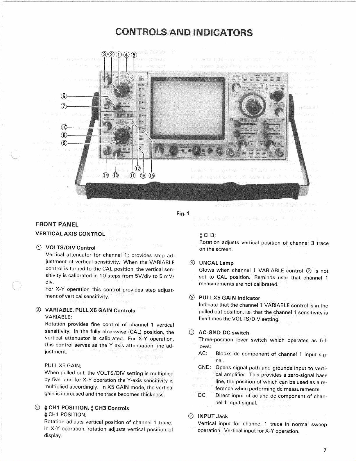
®VOLTS/DIVControl
Vertical
attenuator
for
channel
2;
providesstep
ad-
justment
of
verticalsensitivity,VARIABLEcontrol
is
turned
to
theCALposition,theverticalsensitivity
cali-
brated
in10
stepsfrom5V/div
to
5mV/div.
For
X-Y
operationthecontrolprovidesstepadjustment
of
hor-
izontalsensitivity.
(DVARIABLE,PULLX5GAINControls
VARIABLE;
Rotationprovidesfinecontrol
of
channel
2
vertical
sensitivity.
Inthe
fullyclockwise(CAL)position,
the
vertical
attenuator
is
calibrated.
ForX-Y
operation,
this
controlserves
astheX
axis
attenuationfine
ad-
justment
PULLX5
GAIN;
When
pulledout,theVOLTS/DIVsetting
is
multiplied
byfive
andfor
X-Yoperation
the
X-axis
sensitivity
is
multipliedaccordingly.
InX5
GAIN
mode,
thevertical
gain
is
increasedandthetracebecomesthickness.
®CH2$ POSITIONX-Y$ CH4Controls
*
CH2POSITION;
Rotationadjustsverticalposition
of
channel
2
trace.
In
X-Yoperationadjustshorizontalposition
of
display.
$CH4;
Rotationadjustsverticalposition
of
channel
4
trace
onthescreen.
®UNCALLamp
Glowswhenchannel
2
VARIABLEcontrol
® isnot
set
toCAL
position.Remindsuserthatchannel
2
measurementsare
not
calibrated.
@
PULLX5GAINIndicator
Indicates
that
the
channel
2
VARIABLEcontrol
isin
thepulled
out
position,i.e.thatthechannel
2
sensitiv-
ity
isfivetimestheVOLTS/DIVsetting.
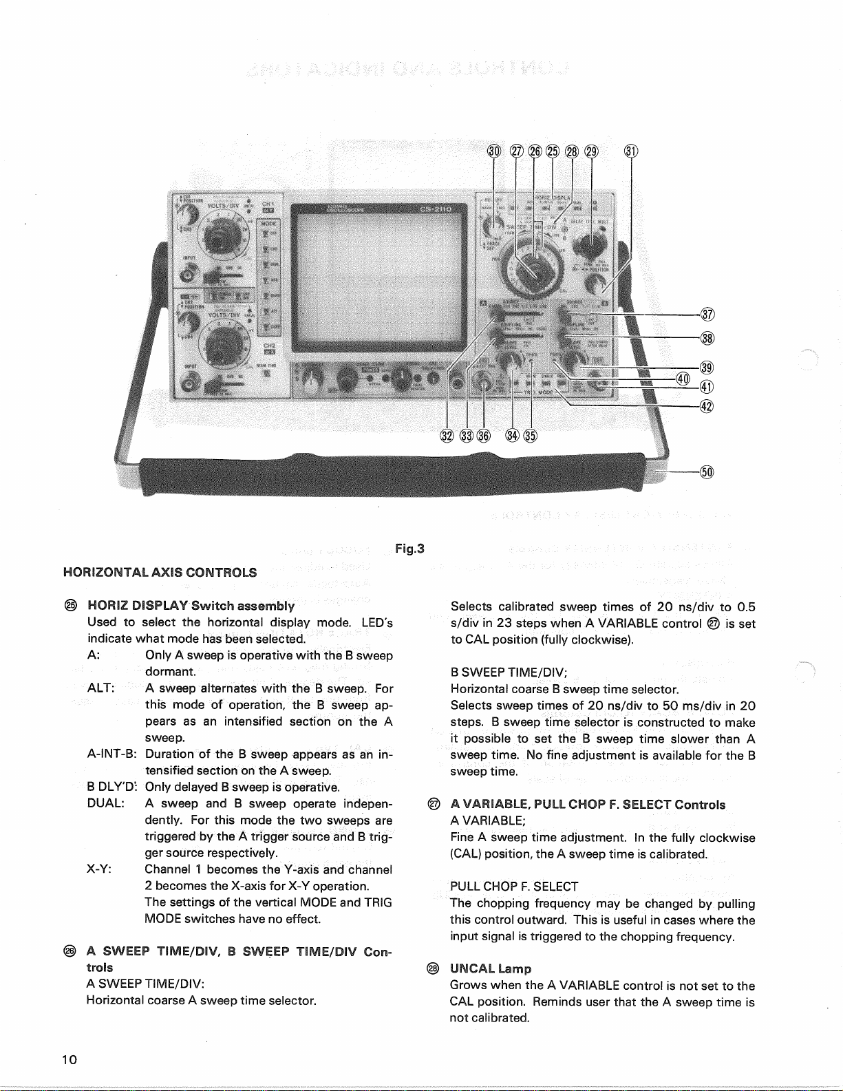
©MODESwitchAssembly
Used
to
selectthebasicoperatingmodes
of
the
osci-
lloscope.LED'sindicatewhat
mode
hasbeen
select-
ed.
CH1:
Onlytheinputsignal
to
channel
1 is
dis-
playedas
a
singletrace.
CH2:Onlytheinputsignal
to
channel
2 is
dis-
playedas
a
singletrace.
DUAL:
When
engagedthisbutton,
if
eitherALT
orCHOPswitch
is
pushed
in,
dualtrace
mode
presentstraces
of
channel
1,
channel
2
inputwaveforms.
ADD:Channel
1 and
channel
2
inputsignals
are
added
and
thesum
is
displayed
asa
singletrace.
When
theCH2INV
button
is
engaged,
the
waveformfromchannel
2
issubtractedfromthechannel1 wave-
formandthedifference
is
displayedas
a
singletrace.
QUAD:
When
engagedthisbutton,
if
eitherALT
orCHOPswitch
is
pushedin,quadtrace
mode
presentstraces
of
channel
1
through
channel
4
inputwaveforms
ALT:
Alternatesweepisselectedregardless
of
sweeptimeasdualtrace(channel
1 and
channel
2)or
quadtrace(channel
1
through
channel
4)
CHOP:
Chop
sweep
is
selectedregardless
of
sweeptimeatapproximately250kHzas
dualtrace(channel
1 and
channel
2)or
quadtrace(channel
1
through
channel
4).
CH2INV:
Inthe
NORM
position(buttonreleased),
thechannel
2
signal
is
non-inverted.
In
the
INV
position(buttonengaged),
the
channel
2
signalisinverted.
20
MHzBW:
Limitstheverticalbandwidth
to
approxi-
mately
20MHz
whenengagedthisbut-
ton.
®AC-GND-DCSwitch
Three-positionleverswitchwhichoperates
as
fol-
lows:
AC:Blocks
dc
component
of
channel
2
input
signal.
GND:Openssignalpath
and
groundsinput
to
vertical
amplifier.Thisprovides
a
zero-
signalbaseline,theposition
of
whichcan
beused
asa
referencewhenperforming
dcmeasurements.
DC:Directinput
ofacanddc
component
of
channel
2
inputsignal.
®INPUTJack
Vertical
input
for
channel
2
trace
in
normalsweep
operation.HorizontalinputinX-Yoperation.
NOTE:
Thevariousvertical
mode
settingsarerelated
to
hori-
zontal
mode
and
triggersource.See
the
sections
on
HORIZDISPLAYandSOURCE
fora
description
of
this
relationship.
©BEAM
FIND
PushButtonSwitch
Limit
thedisplay
to
withinthegraticulearea,indepen-
dently
of
displayposition.
8