manuals.online logo
Brands
  1. Home
  2. •
  3. Brands
  4. •
  5. CFM
  6. •
  7. Fan
  8. •
  9. CFM DVK-T Maintenance and service guide

CFM DVK-T Maintenance and service guide

Installation & Maintenance
DVK-T DRYER BOOSTER KIT
W/
SPRING WOUND TIMER
READ AND SAVE THESE INSTRUCTIONS FOR FUTURE REFERENCE
SAFETY INSTRUCTIONS
DVK100B fans are not explosion proof and should not be used when a potentially
explosive situation exists. Do not use where temperatures will exceed 140 F/60C.
1. Ensure that the electrical service to the fan is locked in the “OFF” position. Do not re-establish
power supply until fan and activation device are completely installed.
2. DVK100B fans are not suitable for outdoor use.
3. This unit has rotating parts! Safety precautions must be exercised during installation, operation
and maintenance. Turn centrifugal impeller by hand to make sure it rotates freely.
4. For general ventilation use only. Do not use to exhaust hazardous or explosive materials
and vapors.
5. To reduce the risk of fire, electric shock, or injury to persons — observe the following:
a. Use this unit only in the manner intended by the manufacturer. If you have questions, contact
the factory.
b. A qualified person(s) must perform installation work and electrical wiring in accordance
with all applicable codes and standards, including fire-rated construction.
c. The combustion airflow needed for safe operation of fuel burning equipment may be
affected by this unit’s operation. Follow the heating equipment manufacturer’s guidelines
and safety standards as published by the National Fire Protection Association (NFPA), the
American Society of Heating, Refrigeration, and Air Conditioning Engineers (ASHRAE), and
local code authorities.
d. When cutting or drilling into walls or ceilings, take care not to damage electrical wires or
other hidden utilities.
e. Ducted fans must always be vented to the outdoors when used to exhaust moist/humid air.
6. Check voltage at the fan to see that it corresponds to the motor nameplate.
DVK100B-T KIT
Kit includes:
Part # Description
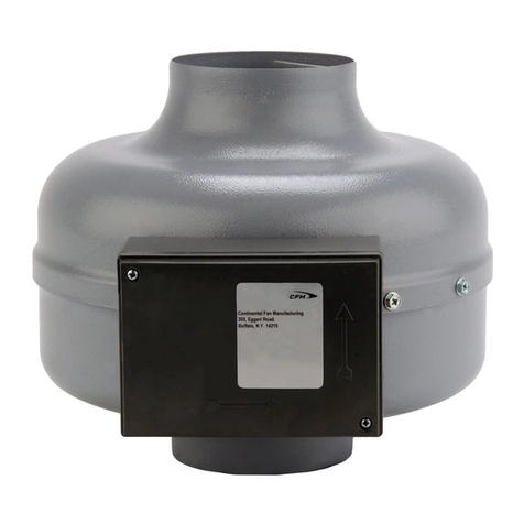
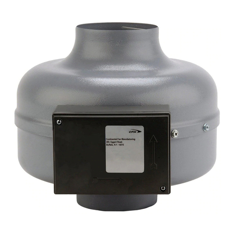
AXC100B In-Line Fan
B150 ounting Brackets (Set of 2)
CT100V Spring wound timer 0-1 hour
DVK-NTC Fan Location Label
DVK-P-I& Installation & aintenance anual
SPRING WOUND INTERVAL TIMER
This spring wound timer will automatically turn the fan off after a preset period. For automatic
operation, turn timer clockwise to desired drying time. Timer will turn “OFF” at the end of preset
timed period.
NOTICE
FAN INSTALLATION
Disconnect and lock out power supply before performing any installation work.
Working on or near energized equipment could result in death or serious injury.
NOTE: The DVK100B dryer booster fan is designed for use in duct runs with an equivalent length
between 25 and 110 feet.
NOTE: An auxiliary lint trap (LT100) may be installed between the dryer and the booster fan.
STEP 1. FAN LOCATION
Fan should be mounted a minimum of 15’ from the dryer outlet. Allow sufficient access to the
fan for recommended maintenance. Affix ‘Fan Location Label’ in a visible place.
STEP 2. INSTALL FAN
Attach mounting brackets to the fan housing as shown in Figure 1a or Figure
1b. Please note the airflow direction arrow located on the box cover. Secure
the fan to a support at the selected location. The fan may be mounted in any
position; however, vertical orientation is recommended to reduce condensation
build-up in the fan. The terminal box should be positioned for easy access.
STEP 3. CONNECT DUCT
Rigid duct is recommended to optimize fan performance. If using flex duct, it
should be stretched as smooth as possible. For duct runs in unheated spaces,
insulated duct is recommended to reduce the effects of condensation.
Connect duct to the inlet and outlet ends of the fan housing by means of
mounting clamps or duct tape and seal to prevent air leakage and loss of fan
performance.
TIMER INSTALLATION
STEP 4. INSTALL TIMER
The timer fits easily in a standard electrical box. If using an existing switch, remove wall plate and
disconnect switch from electrical box. Strip wire ends ½” long using strip gauge on back of timer.
Insert the stripped wire ends under the pressure plate of terminal screws on the side of timer and
screw down tightly using the screws provided.
Insert wired timer into the electrical box with “TOP” properly positioned and fasten timer to box
using the screws provided. Slip metal dial plate over threaded extension with “OFF” position facing
up. Fasten metal dial plate securely to timer with stamped nut provided.
STEP 5. CONNECT WIRING
Refer to wiring diagram below. Reattach all electrical box covers before applying power.
Figure 1a
Figure 1b
WARNING
TROUBLESHOOTING
Only qualified personnel should work on electrical equipment. Working on or
near energized equipment could result in death or serious injury.
1. If the fan fails to start, consult wiring diagram to ensure proper connection.
2. Check the incoming supply for proper voltage.
3. Ensure that the electrical service to the fan is locked in the “OFF” position.
4. Use a meter to test for continuity across the fan motor leads.
5. If the motor leads show continuity, rewire the fan and timer.
6. Turn on the electrical supply and restart. If fan fails to start, remove the timer from the circuit.
7. Connect the incoming power supply directly to the fan motor. Turn on power to fan.
8. If fan fails to start, please contact factory.
RECOMMENDED MAINTENANCE
Disconnect and lock out power supply before performing any maintenance.
Working on or near energized equipment could result in death or serious injury.
1. Fan bearings are sealed. No additional lubrication is necessary.
2. Periodic inspection, based upon usage, should be performed to ensure that the fan impeller is
not obstructed. The fan should be inspected a minimum of every six (6) months.
3. Excessive fan noise or vibration may indicate an obstructed impeller.
4. To inspect and clean impeller:
a)Remove the duct from the fan inlet and remove any obstruction from the impeller.
b)Reconnect the duct to the fan.
c)Turn power supply on.
WIRING DIAGRAM
WARNING
WARNING
NOTE: JUMPER MUST BE USED WHEN
MOTOR IS OPERATED WITH FAN TIMER
GREEN
WHITE
BLACK
CAPACITOR
BLACK
WHITE
GREEN
BROWN
BLACK
BLUE
YELLOW
FAN
MOTOR 117 VOLT SUPPLY
FROM FUSE PANEL
WHITE JUMPER
FAN TIMER
OFF
TERMINAL
BLOCK
DVK-T-I&M-1603
1-800-779-4021 • www.continentalfan.com
Continental Fan Manufacturing Inc.
203 Eggert Road
Bualo, New York 14215
Continental Fan Manufacturing Inc.
6274 Executive Blvd.
Dayton, Ohio 45424
Continental Fan Canada Inc.
12-205 Matheson Blvd E
Mississauga, Ontario L4Z 3E3

This manual suits for next models

1

Other CFM Fan manuals

CFM ADD-0911 User manual

CFM

CFM ADD-0911 User manual

CFM TNC-0506 User manual

CFM

CFM TNC-0506 User manual

CFM AeroFan User manual

CFM

CFM AeroFan User manual

CFM TBF120 Installation and operating instructions

CFM

CFM TBF120 Installation and operating instructions

CFM RMD-0807 User manual

CFM

CFM RMD-0807 User manual

CFM APK-0906 User manual

CFM

CFM APK-0906 User manual

CFM TF400 Maintenance and service guide

CFM

CFM TF400 Maintenance and service guide

CFM 165834 User manual

CFM

CFM 165834 User manual

CFM 165596 User manual

CFM

CFM 165596 User manual

CFM CDB-07 User manual

CFM

CFM CDB-07 User manual

CFM ECO-FLO Maintenance and service guide

CFM

CFM ECO-FLO Maintenance and service guide

CFM ABP-0905 User manual

CFM

CFM ABP-0905 User manual

CFM MFT Series Maintenance and service guide

CFM

CFM MFT Series Maintenance and service guide

CFM MNC-250 User manual

CFM

CFM MNC-250 User manual

CFM CEB-0807 User manual

CFM

CFM CEB-0807 User manual

CFM APW-0906 User manual

CFM

CFM APW-0906 User manual

CFM HRV-0904 User manual

CFM

CFM HRV-0904 User manual

CFM SEF Installation and operating instructions

CFM

CFM SEF Installation and operating instructions

CFM 167193 User manual

CFM

CFM 167193 User manual

CFM WEB-0807 User manual

CFM

CFM WEB-0807 User manual

CFM CF Maintenance and service guide

CFM

CFM CF Maintenance and service guide
CFM GEF10 Operating and safety instructions

CFM

CFM GEF10 Operating and safety instructions

CFM FCU-08 User manual

CFM

CFM FCU-08 User manual

CFM TF140-DC Maintenance and service guide

CFM

CFM TF140-DC Maintenance and service guide

Popular Fan manuals by other brands

NuAire MRXBOXAB-ECO3B-1ZSW installation manual

NuAire

NuAire MRXBOXAB-ECO3B-1ZSW installation manual

Be Cool BC121TU2201F manual

Be Cool

Be Cool BC121TU2201F manual

Condair MD Series installation manual

Condair

Condair MD Series installation manual

Harbor Breeze Teolo manual

Harbor Breeze

Harbor Breeze Teolo manual

Aspira ASPIRCOMFORT PRO dH Installation, use and maintenance manual

Aspira

Aspira ASPIRCOMFORT PRO dH Installation, use and maintenance manual

RingGrip R2000B manual

RingGrip

RingGrip R2000B manual

Dimplex GDC-TF75RW instruction manual

Dimplex

Dimplex GDC-TF75RW instruction manual

Bimar VC95 Instruction booklet

Bimar

Bimar VC95 Instruction booklet

Cumberland Mega-Flow 24 manual

Cumberland

Cumberland Mega-Flow 24 manual

Vortice VORT HRW 20 MONO Instruction booklet

Vortice

Vortice VORT HRW 20 MONO Instruction booklet

Fanimation Air Shadow FP810 Series owner's manual

Fanimation

Fanimation Air Shadow FP810 Series owner's manual

enervent Pinion Operation and maintenance instructions

enervent

enervent Pinion Operation and maintenance instructions

Acorn DC-159 instruction manual

Acorn

Acorn DC-159 instruction manual

Vortice NORDIK HVLS SUPER BLADE E instruction manual

Vortice

Vortice NORDIK HVLS SUPER BLADE E instruction manual

Carrier FMC4X installation instructions

Carrier

Carrier FMC4X installation instructions

Hunter Overture installation manual

Hunter

Hunter Overture installation manual

Strend Pro FS4014C instruction manual

Strend Pro

Strend Pro FS4014C instruction manual

Holmes HTF3110A owner's guide

Holmes

Holmes HTF3110A owner's guide

manuals.online logo
manuals.online logoBrands
  • About & Mission
  • Contact us
  • Privacy Policy
  • Terms and Conditions

Copyright 2025 Manuals.Online. All Rights Reserved.