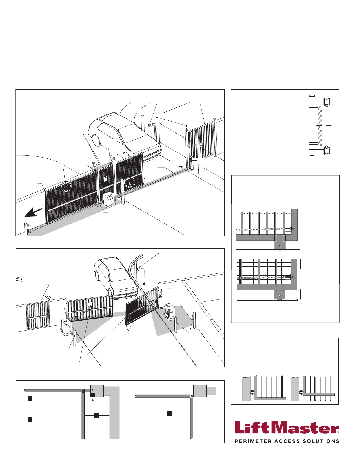
Base of Swing and Slide Gate
OK Not Allowed
All Gates must have smooth bottom edges, no protrusions
should exist. If gate hardware or sensors protrude, they
must have smooth surfaces free of any sharp cutting edges
that do not exceed ½ inch beyond the base of the gate.
(ASTM F2200: 4.8)
Slide Gate Site Layout Guidelines
Public Side
Secure Side
Left Hand Gate
opening
Physical stop - weld stops at both ends of gate rail.
Photo eye (entrapment protection shown in four locations)
Edge sensor
on Trailing Edge
of gate
Edge sensor on
Leading edge of gate
See “Slide Gate Openings”
See “Slide Gate Openings” V track
(gate rail)
Physical
stop
Non-pinch
rollers (4x)
Photo eye (4x)
Guard
posts
ENTRAPMENT ZONE
Attach WARNING signs on
both sides of the gate area
User controls mounted at
least 6 ft. away from gate
Pedestrian gate
clearly located
6 ft. minimum
Photo eye
Public Side
Swing Gate Site Layout Guidelines
Secure Side
Pedestrian gate
clearly located
Attach WARNING signs on
both sides of the gate area
User controls mounted at
least 6 ft. away from gate
Photo
eyes
ENTRAPMENT
ZONE
Photo
eye
Edge
sensor Photo eyes
ENTRAPMENT
ZONE
Photo eye
Gate Frame and Adjacent Fence Area
6 ft. minimum
X X XX X XX X X XXXXXXXX X
Gate Frame and Adjacent Fence Area
If gaps (xxx)
between vertical
bars of the gate or
fence are less
than 2 1/4", no
further screening
is required.
For gaps (xxx)
equal to or larger
than 2 1/4", a wire
mesh screen must
be applied to the
gate. Wire mesh
screen openings
must be smaller
than 2 1/4". The
minimum height of
wire mesh screen:
6 ft. above grade.
Slide Gate Openings Guidelines
Openings of a horizontal slide gate must be smaller than 2 1/4"
or else be guarded or screened. These design rules apply to
both the moving gate as well as the portion of adjacent fence
that the gate covers in the open position (UL 325: 56.8.4.a.2
and ASTM F2200: 6.1.2). See Illustrations below.
Slide Gate Spacing Guidelines
Slide Gate Gaps
A gap, measured in the horizontal plane
parallel to the roadway, between a fixed
stationary object nearest the roadway
(such as a gate support post) and the gate
frame when the gate is in either the fully
open position or the fully closed position,
shall not exceed 2 ¼ in.. Exception: All
other fixed stationary objects greater than
16 in. from the gate frame shall not be
required to comply with this section.
(ASTM F2200: 6.1.4)
Swing Gate Clearance Guidelines
With the hinge mounted on
the corner of the pilaster, the
entrapment area is
eliminated and protection is
not required for this area.
A
(ASTM F2200: 7.1.1.1 and 7.1.1.2)
Closed Gate
A
B
Closed Gate
B
If space is greater than 4",
entrapment protection in
this area is required.
If space is less than 16",
entrapment protection in
this area is required.
A
Getting Started with Swing and Slide Gate Operator Safety
• Only install the operator on gates used for vehicular trafc.
• A separate pedestrian entry/exit must be clearly visible to promote
pedestrian usage and located so pedestrians do not come in contact
with the vehicular gate while it is moving.
• Install two independent entrapment protection devices protecting
each entrapment zone.
• Pickets of a slide gate must be designed or screened to prevent
persons from reaching through, or passing through a gate.
See your owner’s manual for complete details regrading your LiftMaster®Perimeter Access Solution.
Always design, install and maintain safe gate access systems in accordance with UL 325 & ASTM F2200 standards
Illustrations and content provided by DASMA Gate Systems Safety Guide
352373-3 PRO4751 Gate Safety Checklist.indd 2 8/31/15 4:41 PM


