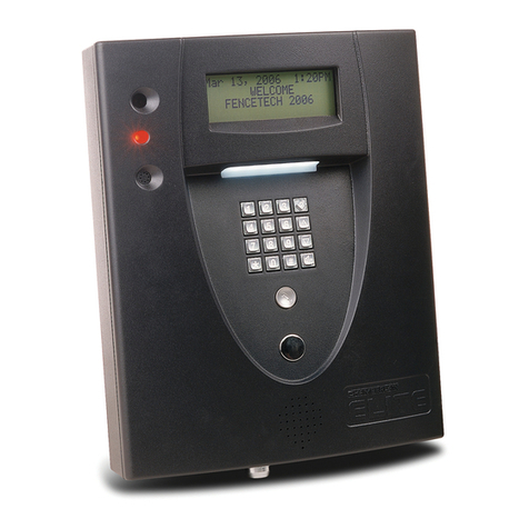
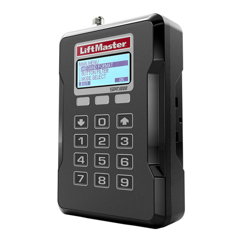
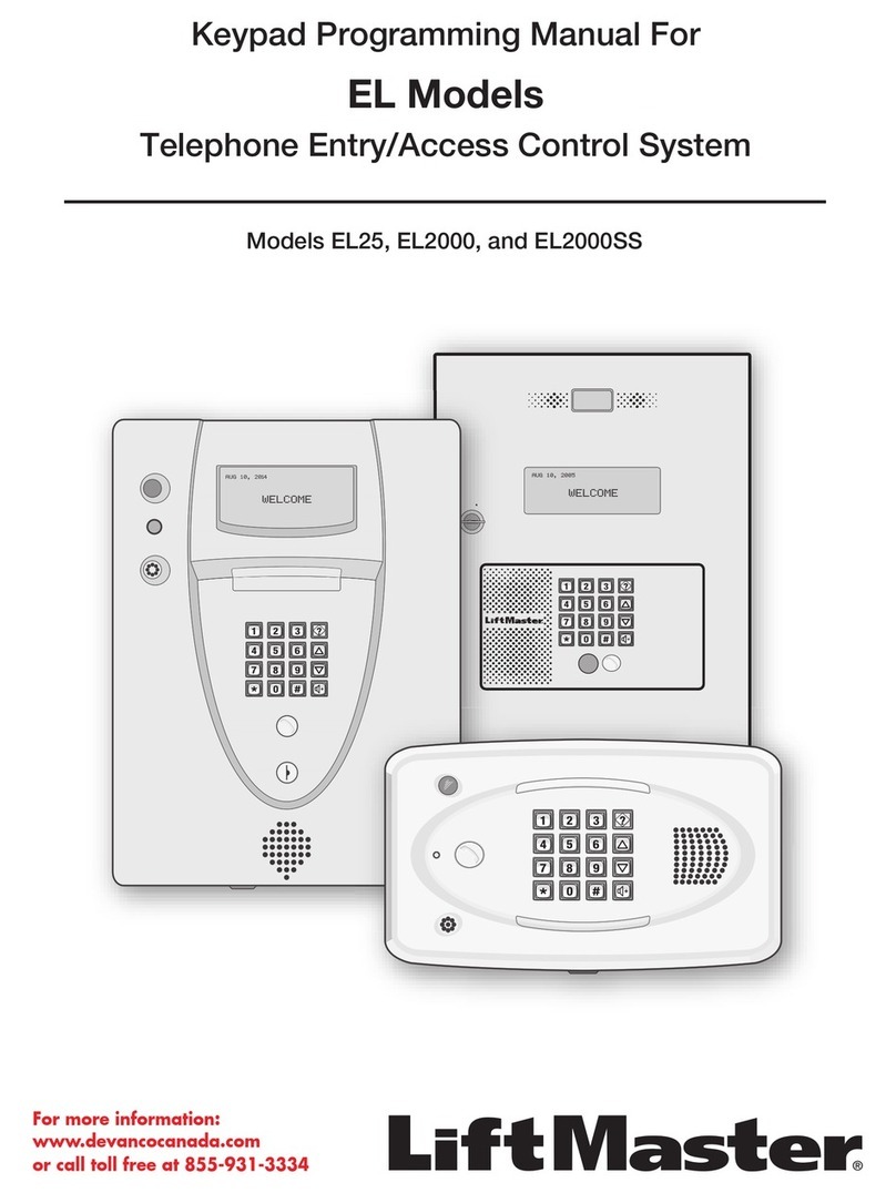
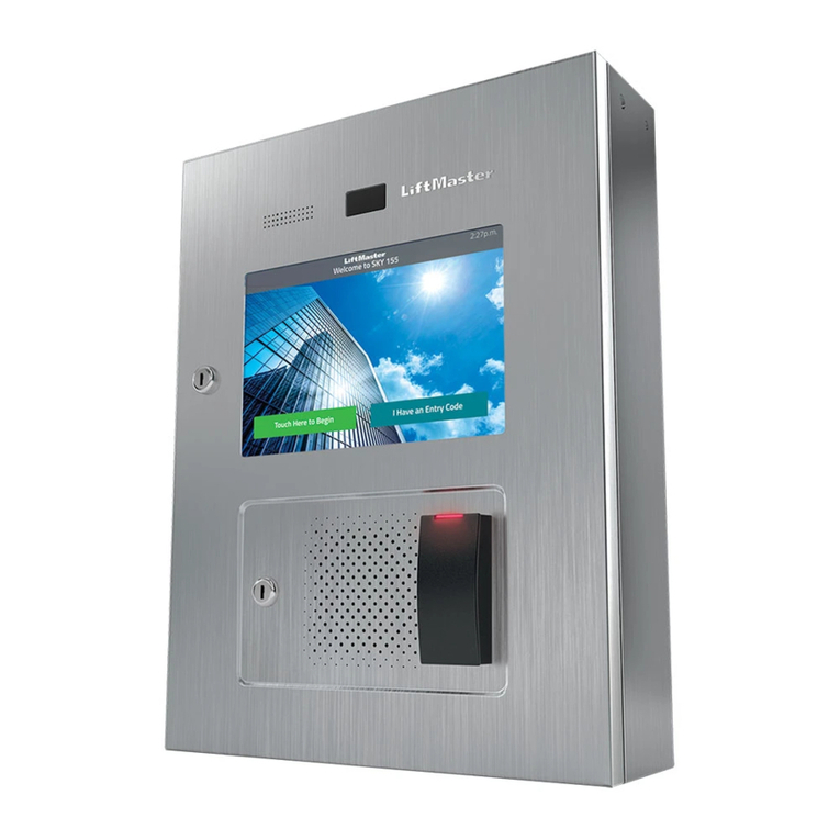
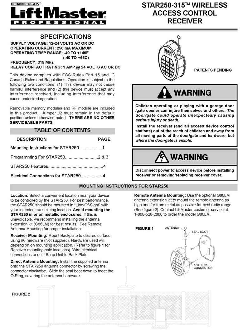
Chamberlain EL Series Owner's manual

Keypad Programming Manual For
EL Models
Telephone Entry/Access Control System
Models EL25 and EL2000SS
LiftMaster
300 Windsor Drive
Oak Brook, IL 60523
LiftMaster.com
For how-to videos, visit the
LiftMaster Training Academy at
LiftMastertraining.com

1
1. CCTV Camera: Optional
2. Call Button: Press to call a resident inside the complex, or office.
3. Status LED: Solid Red (EL25 idle power, doors are locked); Blinking Red
(Strikes and Out for a door); Solid Green (Granted access for a
door); Blinking Green (Latch for a door is unlocked). NOTE: All
references are for door 1.
4. Microphone
5. Asterisk Key: "Start Programming Mode" or a Cancel Key.
6. Pound Key: Data field separator, optional skip step or enter key.
Call a resident using the directory codes.
7. Visitor Volume Key: Visitors can physically adjust the speaker
volume of the unit. Unit will return to programmed volume setting
when transaction complete.
8. Up/Down Key: Serves no function on this unit.
9. Help Key: Receive a quick audio description of a keypad button by
pressing the Help key followed by the key to be described.
10. Lights: Top and Bottom of Keypad.
11. Speaker: Allows resident and visitors to communicate; plays responses to
communicate programming or function commands.
EL25
1. CCTV Camera: Optional
2. Call Button: Press to call a resident
inside the complex, or office. Also
when calling someone using the
directory code listing.
3. Microphone
4. Asterisk Key: "Start Programming
Mode" or a Cancel Key.
5. Pound Key: Data field separator,
optional skip step or enter key. Call a
resident using the directory codes.
6. Visitor Volume Key: Visitors can
physically adjust the speaker volume of
the unit. Unit will return to
programmed volume setting when
transaction complete.
7. Up/Down Key: For scrolling through
tenant listing.
8. Help Key: Receive a quick audio
description of a keypad button by
pressing the Help key followed by the
key to be described.
9. Speaker: Allows resident and visitors
to communicate; plays responses to
communicate programming or function
commands.
10. LCD Display (optional)
11. Postal Plug
KEYPAD PROGRAMMING GUIDE
11
11
10
11
2
6
5 7
8
9
4
3
1
10
9
11
2
3
1
5
4
6
7
8
EL2000SS

2
TABLE OF CONTENTS
Programming Numbers Page
Quick Reference Guide (Default Factory Settings) “ALL” 4-8
Introduction
Single Family Residence (NPB) 9
Multi-Resident Complex (Dial-Out or Manager Sharing) 9-10
Sample Layouts and Your System Layout 11-13
Programming Single Unit Overview
Programming Basics 14-15
Enter Programming Mode *** + 6-Digit Password 16
Exit Programming Mode 016
System Feedback / Responses (Beeps) 17-18
Sending Direct Commands from Resident’s Phone 19
Programming Multiple Units Overview 2 111 20
Setup “Your Settings”
Getting Started 1 3 21
Setup External Access Control Devices 60 61 65 66 22-24
Your Door Settings with Examples 25
Example Setups 26-27
Directory Codes
About Directory Codes 28
Set a Directory Code Length 629
Add, Edit, or Delete Directory Codes 40 41 44 48 29-30
Delete ALL Directory Codes 201 31
Enable or Disable Do Not Disturb Schedule 10 31
Enable or Disable Call Forwarding (Directory Calls) 46 31
Add/Modify Resident DnD and/or Call Forwarding 49 32
Activate or Deactivate a Directory Code 45 32
Directory Code Display Option/Resident Display Option 141 33
Verify a Directory Code 47 33
Entry Codes
About Entry Codes 34
Set an Entry Code Length 735
Add, Edit, or Delete Entry Codes 50 51 54 57 75 58 59 202 35-38
Activate or Deactivate an Entry Code 56 38
Verify an Entry Code 55 38
Access Cards
About Cards 39
Add, Edit, or Delete Cards 78 80 81 82 88 203 40-42
Activate or Deactivate a Card 87 42
Verify a Card 86 43
Facility Codes 74 73 43
Card Types 71 43

3
TABLE OF CONTENTS
Programming Numbers Page
Remote Controls 44
Time Zones, Holidays and Clock
About Time Zones 44
Creating Time Zones 30 45
Setting Holidays 32 45
Assigning Door Use and Unlock Time Zones 63 11 31 46
Deleting ALL Time Zones 205 47
Setting the Clock 3 4 47
Features
Setting Anti-Passback 12 64 13 105 58 48-49
Configuring the Alarm Features 102 103 17 104 49-50
Changing or Verifying the Unit Password 151
Communications to and from Unit
Telephone-Unit Settings 115 16 109 113 20 110 52-54
Call Quality Settings 18 19 106 54
Enable or Disable Call Waiting 955
Maximum Modem Speed 118 55
Visitor Communication Settings 23 22 116 5 26 160 25 56-57
LCD Visitor Messages 58-59
Postal Lock/Autocall/Exit/Door Sensor Devices
Postal Lock Switch 69 60
Autocall Device 70 60
Request to Exit Device (REX) 67 61
Door Sensing Devices 68 62
Direct Commands from the Phone 21 120 121 122 123 124 125
126 63-65
Real-Time Monitoring 24 66
Reset/Restore the Unit and Database 28 29 206 66
Warranty 67
Glossary 68-69
Appendix 70-71

4
GUIDE FOR KEYPAD PROGRAMMING THE UNITS
Optional Steps Indicated in BOLD type, all other steps are Required.
Programming
Number Page Description of Task Factory
Setting
Programming
Procedure
*** 16 Entering Programming Mode *** (6 Digit Password)
016
Exiting Programming Mode 0 #
151
Change or Verify the Unit’s
Password
000000 1 # (1 to change; 2 to verify) # (six-digit
coded) #
220
Set Unit ID Number and No. in Chain Unit ID 1,
Chain No. 1 2 # (unit ID number, 1-7) #
(Number of Units in Chain, 1-7) #
347
Set the Clock 3 # yymmdd # (day of the week) # hhmm #
447
Enable/Disable Daylight Savings
Time Enabled 4 # (0=disable; 1=enable) #
557
Set Visitor Talk Time 60 Seconds 5 # (15-250 seconds) #
629
Set Directory Code Length 3 Digits 6 # (1-4 ) #
735
Set Entry Code Length 4 Digits 7 # (3-9) #
955
Enable/Disable Call Waiting Enabled 9 # (0=disable; 1=enable) #
10 31 Enable/Disable Do Not Disturb
Schedule Disabled 10 # (directory code) # (0=disable;
1=enable) #
11 46 Enable/Disable Unlock Schedule Enabled 11 # (0=disable; 1=enable) #
12 48 Enable/Disable Anti-Passback Disabled 12 # Enable/Disable True Anti-Passback
(0=disable; 1=enable) # Enable/Disable
Timed Anti-Passback (0=disable; 1=enable) #
13 48 Set Anti-Passback Time 3 Minutes 13 # (1-60 minutes) #
14 Set Maximum Number of Rings
Allowed Before Aborting Attempt 5 Rings 14 # (1-9) #
15 Set Standard Single Ring or Double
Ring Response 1=Double
Ring 15 # (0-1; 0=one long ring, 1=double ring)
#
16 53 Number of Rings Before Unit
Answers 5 Rings 16 # (0-15) # Each unit in chain must have
same setting
17 50 Set “Strikes and Out” 3 Errors 17 # (max errors, 0-5) #
18 54 Set Speaker
Set Voice Response Volume
Set Beep Response Volume
5, 2, 2 18 # (0=mute; 1-10, 1 is low and
10 is high) # (0=mute; 1=low;
2=medium; 3=high) # (0-3) #
19 54 Set Microphone Volume 5 19 # (0=mute, 1-10, 1 is low and 10 is
high) #
20 53 Enable/Disable the Telco Mode Enabled 20 # (0=disable; 1=enable) #
21 63 Enable/Disable Direct Commands Enabled 21 # (0=disable, 1=enable) #
22 56 Enable/Disable Voice Mail Disabled 22 # (0=disable, 1=enable) #
23 56 Enable/Disable Access Granted
Beeps Enabled 23 # (0=disable, 1=enable) #
24 66 Enable/Disable Real-Time Monitoring Disabled 24 # (0=disable, 1=enable) #
25 57 Return to Menu Programming 25 #
26 57 Enable/Disable “Announce All Doors/
Access Granted” Disabled 26 # (0=disable, 1=enable) #
IMPORTANT: The Pound Key (#) must be used as Data Field Separator and to Save Data at the end of the sequence.
Time must be entered using a 24-hour format (8am=0800, 3pm=1500 etc.). If you make an error during an entry,
press the asterisk key (*) to begin again.
QUICK REFERENCE GUIDE

5
Programming
Number Page Description of Task Factory
Setting
Programming
Procedure
28 66 Restore Factory Settings 28 # 101010 #
29 66 Reset the Unit 29 # 101010 #
30 45 Create a Time Zone 30 # (time zone number, 2-63) # (segment
number; 99) # (starting time=hhmm; 99) #
(ending time=hhmm) # (day of week, 1-8;
1=Sunday; 7=Saturday; 8=holiday) #
31 46 Assign Door Auto Lock/Unlock
Schedule Disabled 31 # (door 1-4) # (time zone, 2-63; 99) #
32 45 Setting Holidays 32 # (1=add, 2=verify, 0=delete) # (yymmdd;
yy=year, mm=month, dd=day of the month) #
40 29 Add a Basic Directory Code Enabled 40 # (directory code) # (phone number) # (phone
extension) #
41 30 Add or Edit a Full Function
Directory Code 41 # (directory code) # (phone number) # (phone
ext) # (DnD schedule number, 0-63) # (enable/
disable call fwd) # (call fwd schedule number,
0-63) # (new call fwd phone number) # (call
fwd phone ext) #
44 30 Change a Directory Code
ONLY 44 # (new directory code) # (directory code to
change) #
45 32 Activate/Deactivate a Directory
Code 45 # (directory code) # (0=deactivate; 1=activate)
# (0=don’t use start; 1=use start) # (Start
Date=yymmdd) # (Start Time=hhmm) # (0=don’t
use end; 1=use end) # (End Date=yymmdd) #
(End Time=hhmm) #
46 31 Enable/Disable Call Forwarding
(Directory Calls) Disabled 46 # (directory code) # (0=disable; 1=enable) #
(schedule number, 0-63) # (new call forward
phone number) # (call forward phone
extension) #
47 33 Verify a Directory Code 47 # (directory code) #
48 30 Delete a Directory Code 48 # (directory code) #
49 32 Enable/Disable Call Forwarding
and Do Not Disturb Schedule
with Residence “Call Button”
Only
Disabled 49 # DnD Enable (1)/Disable (0) # DnD Schedule
(0-63) # Call Forward Enable/Disable
(0=disable; 1=enable) # Call Forward Schedule
(schedule number, 0-63 # (new call forward
phone number) # (call forward phone
extension) # (call forward extension delay, 0 to
30 sec.) #
50 35 Add a Basic Entry Code 50 # (entry code) #
51 36 Add/Edit a Full Function Entry
Code 51 # (entry code) # (schedule for door 1, 0-63)
# (schedule for door 2, 0-63) # (schedule for
door 3, 0-63) # (schedule for door 4, 0-63) #
54 36 Change Entry Code ONLY 54 # (entry code to change) # (new entry code) #
55 38 Verify an Entry Code 55 # (entry code) #
56 38 Activate/Deactivate an Entry
Code 56 # (entry code) # (0=deactivate; 1=activate) #
(0=don’t use start; 1=use start) # (Start
Date=yymmdd) # (Start Time=hhmm) # (0=don’t
use end; 1=use end) # (End Date=yymmdd) #
(End Time=hhmm) #
QUICK REFERENCE GUIDE

6
QUICK REFERENCE GUIDE
Programming
Number Page Description of Task Factory
Setting
Programming
Procedure
57 36 Delete an Entry Code 57 # (entry code) #
58 37 Assign Utility Option Off 58 # (entry code) # (Option; 0=Off,
1=Daily, 2=Weekly, 3=Never) # (number
of uses 1-15)
59 37 Assign Special Use Entry Code 59 # (entry code) # enable/disable #
60 24 Assign Each External Access
Control Device a “Door Number” Main keypad
assigned door1
Device 1=door 1
Device 2=door 2
Device 3=door 3
Device 4=door 4
60 # (device 1-4) # (door 1-4) #
61 24 Assign “Each” Door Number to
One or More Relays D1=Relay 1
D2=Relay 2
D3=Relay 3
D4=Relay 4
61 # (door 1-4) # (relays to activate
0000-1111) # Order of relay is: relay
4-relay -3 -relay 2-relay 1 for an example
if you want relay 4 active you would enter
1000, if you want relay 1 active you
would enter 0001
63 46 Assign Door Use Time Zone Enabled 63 # (door 1-4) # (time zone, 0-63) #
64 48 Set Anti-Passback Entry/Exit for
Specific Devices Disabled 64 # (device 0-4) # (0-3; 0=disable, 1=set
device to timed anti-passback, 2=set
device to true anti-passback-entrance,
3=set device for true anti-passback-exit)
#
65 23 Set Each “Relay Mode” to get
the Appropriate Response All Relays =
“1-Strike” 65 # (relay 1-4) # (1=strike, 2=shunt,
4=alarm, 5=control) #
66 23 Set Each Relay’s “Activation
Time” All Relays =
10 seconds 66 # (relay 1-4) # time (1-300 seconds)
67 61 Request to Exit Device (REX) R1=Door 1
R2=Door 2
R3=Door 3
R4=Door 4
67 # (REX number 1-4) # (select REX
option: 0=disabled, 1=use your door
settings or 2=use specific relay(s)
0000-1111) # Order of Relays are 4321
68 62 Door Sensing Devices DS1=Door 1
DS2=Door 2
DS3=Door 3
DS4=Door 4
68 # (sensor number 1-4) # (select
sensor option: 0=disabled, 1=use your
door settings or 2=use specific relay(s)
0000-1111) # Order of Relays are 4321
69 60 Postal Lock Switch Door 1 69 # (door 0-4; 0=no postal lock) #
70 60 Autocall Device 0000 70 # (relays to activate 0000-1111) #
Order of Relays are 4321 (Factory
Default: 0000)
71 43 Set the Default Card Type 30-bit 71 # (26 or 30) # (Factory Default: 30)
73 43 Set the Default Facility Code 0 73 # (0-255) #
74 43 Enable or Disable Ignore Facility
Code when a Card is Used Enabled 74 # (0=disable; 1=ignore) #
75 36 Change Entry Code Door Access All Doors 75 # (entry code) # (door 0=any door,
1=door 1, 2=door 2, 3=door 3, 4=door 4)
#
78 40 Change Card Code Door Access All Doors 78 # (card code) # (facility code) #
(card type, 26 or 30) # (door 0=any door,
1=door 1, 2=door 2, 3=door 3, 4=door 4)
#
80 40 Add a Basic Card 80 (card PIN code) # (facility code) #
(card type, 26 or 30) #

7
QUICK REFERENCE GUIDE
Programming
Number Page Description of Task Factory
Setting
Programming
Procedure
81 41 Add or Edit a Full
Function Card 81 # (card PIN code) # (facility code) (card type, 26 or
30) # (schedule for door 1, 0-63) # (schedule for door 2,
0-63) # (schedule for door 3, 0-63) # (schedule for door
4, 0-63) #
82 41 Add a Group of Cards
at Once 82 # (card PIN code start range) # (card PIN code end
range) # (facility code) # (card type, 26 or 30) #
(0=deactivate, 1=activate) # (schedule for door 1, 0-63)
# (schedule for door 2, 0-63) # (schedule for door 3,
0-63) # (schedule for door 4, 0-63) # name (0-20
characters) #
87 42 Activate or Deactivate
a Card 87 # (card PIN code) # (facility code) # (card type, 6 or
30) # (0=deactivate; 1=activate) # (0=don’t use start;
1=use start) # (Start Date=yymmdd) # (Start Time=hhmm)
# (0=don’t use end; 1=use end) # (End Date=yymmdd) #
(End Time=hhmm) #
88 42 Delete a Card 88 # (card PIN code) # (facility code) # (card type, 26 or
30) #
102 49 Configure “Door Held
Open” Alarm Feature Disabled 102 # (alarm option; 0=disable, 1=enable until relay time
expires, 2=enable until alarm clears) # (relay group, 0000-
1111) # Order of relays is 4321
103 50 Configure “Door
Forced Open” Alarm
Feature
Disabled 103 # (alarm option; 0=disable, 1=enable until relay time
expires, 2=enable until alarm clears) # (relay group, 0000-
1111) # Order of relays is 4321
104 50 Configure “Strikes and
Out” Alarm Feature Disabled 104 # (alarm option; 0=disable, 1=enable until relay time
expires, 2=enable until alarm clears) # (relay group, 0000-
1111) # Order of relays is 4321
105 49 Enable or Disable Anti-
Passback Forgiveness
at Midnight
Enabled 105 # (0=disable; 1=enable) #
106 54 Enable or Disable Echo
Cancellation by
Channel
Enabled 106 # (1=Mic/Spkr; 2=Resident; 3=Telco #; 0=disable;
1=enable)
109 53 Override Telephone
Company Answering
Service
Disabled 109 # (0=no; 1=yes) # Default is “No”
110 54 Set a Phone Number’s
Extension Delay Time No Delays 110 # (directory code) # (phone extension delay) # (call
forward extension delay) #
111 20 Verify Unit Number 111 #
113 53 Dial “0-9” First to Get
an Outside Line Using
a Automated Phone
System
Disabled 113 # (0=disable; 1=enable) # (0-9, when enabled) #
115 52 Set Alternative Prefixes Normal 115 # (normal-00, mixed-01, asterisk-02, pound-03,
number-1n) # each unit in chain must have same setting
116 56 Change the Visitor Call
Response Keys 9, 5, 3, 7,
2, 1,* 116 # (activate door 1) # (activate door 2) # (activate
door 3) # (activate door 4) # (call wait toggle) # (extend
talk time) # (hang up and deny access) #
118 55 Configure Maximum
Modem Speed 14400 118 # Speed (14400, 9600, 2400, 1200) #
120 63 Talk through the Unit
Speaker 120 #
121 64 Cycle Door 121 # (door 1-4) #
8
To enter programming mode from the keypad Press *** and the 6-Digit Password (audio feedback will be heard)
Exiting programming mode allows changes to take effect
IMPORTANT:
• The Pound Key (#) must be used as Data Field Separator and to Save Date at the end of the sequence.
• Time must be entered using a 24-hour format (8am=0800; 3pm=1500 etc.).
• Audio Feedback: Programming input is valid. Audio Feedback: Input is not valid.
• If you make an error during an entry, press the asterisk key (*) to begin again.
QUICK REFERENCE GUIDE
Programming
Number Page Description of Task Factory
Setting Programming
Procedure
122 64 Toggle Door Open/Close Until 122 # (door 1-4) # (end time=hhmm) #
123 65 Get Door Status 123 # (door 1-4) #
124 65 Release Door 124 # (door 1-4) #
125 65 Enable/Disable Call Forwarding For
Residence 125 # (0=disable; 1=enable) #
126 65 Enable/Disable Do Not Disturb For
Residence 126 # (0=disable; 1=enable) #
141 33 Directory Code Display Option/
Resident Display Option 0, 1, 2 or
3141 # (directory code) # (hidden attribute
option) # (hidden option; 0=show name and
code, 1=name only, 2=code only, 3=hide) #
201 31 Delete ALL Directory Codes 201 # 101010#
202 38 Delete ALL Entry Codes 202 # 101010#
203 42 Delete ALL Cards 203 # 101010#
205 47 Delete ALL Time Zones 205 # 101010#
206 66 Delete ALL Access
Codes from Database 206 # 101010#

9
The sample installations on the next few pages will help familiarize you with the features of your unit. You MUST
know how your system is laid out to program it with this manual. If you have questions about your configuration,
please contact your installing dealer for more information.
SINGLE FAMILY RESIDENCE (NPB)
This type of installation utilizes the "No Phone Bill" (NPB) feature. When a visitor contacts the resident at the unit, it
does not dial a separate number to reach you in your residence. The unit essentially functions as an intercom with
your residence phone. Therefore, the NPB does not require the use of directory codes, since the unit will only need to
ring a single telephone line to the house. When a visitor arrives, they will simply press the unit’s "Call" button to
contact the resident.
AUG10, 2005
WELCOME
Telco Phone Line
Bypass
Board
MULTI-RESIDENT COMPLEX (DIAL-OUT)
This installation utilizes the dial-out feature. Each resident has a separate phone number. The unit dials the resident’s
numbers using preprogrammed Directory Codes. Because the unit dials a separate phone number to contact the
resident, the "Call Waiting" and "Direct Command" features will not work. The unit must be remotely programmed.
Telco Phone Lines
Phone Junction Box
Building/Complex
Resident
Resident
Resident
Manager
separate phone number
INTRODUCTION

10
MULTI-RESIDENT COMPLEX (MANAGER SHARING)
With this type of installation, the manager has the same features as the single family residence (page 9). The unit can
be programmed remotely or locally. Visitors can call the manager directly using "Call" button or contact residents
using preprogrammed Directory Codes.
Phone Junction Box
Building/Complex
Resident
Resident
Resident
Manager
separate phone number
Telco Phone Lines
Bypass
Board
NPB MULTI-RESIDENT COMPLEX
Modes of Access
Visitors or residents of a building or complex controlled by a unit can gain access using one of the following
methods:
Resident Phone (Directory Codes): A visitor may dial a resident’s directory code from the unit to contact him/her.
The resident can then decide to grant or deny the visitor access to the building or complex.
Keypad (Entry Codes): A resident may enter a valid entry code on the unit’s keypad or an optional external
Wiegand-compatible keypad to enter the building or complex.
Optional Card Readers (Cards): A resident may present a valid card to an optional Wiegand-compatible card
reader to enter the building or complex. Card readers are typically located near an entry/exit area
(e.g., door or gate).
Optional Radio Frequency Receivers (Remote Controls): A resident may choose to use an optional Passport
remote control or other optional Wiegand-compatible receiver to enter the building or complex. For example, these
may be used to open a vehicular gate.

11
SAMPLE LAYOUT
Single Family Residence (NPB) Example
The unit can operate the vehicular gate with an access code or by remote control. It will allow Pedestrians entry with
an Access Card. It will also open the gate automatically for exiting cars.
Main Keypad
(Driveway)
Wiegand Card Reader
(Pedestrian Gate)
Gate Operator
(Driveway)
Relay 3 - Strike Mode
Unlocks Pedestrian Gate Relay 1 - Strike Mode
Opens Vehicular Gate
Relay 2 - Control Mode
Turns on Light
Relay 4 - Alarm Mode
Signals an alarm pad
(REX) Exit Request

12
SAMPLE LAYOUT
Multi-Resident Complex Example
The unit can control the property with a vehicular gate operator, access card or the unit’s keypad. Residents can use
programmed remote controls for the parking lot, access cards for the pool or a personal entry code for the main
entrance. The main entrance is equipped with a door sensor to alert management about inappropriate use. The exit
sensor will automatically open the gate for exiting cars.
Main Keypad
(Front Door)
Wiegand Card Reader
(Pool Gate)
Gate Operator
(Vehicular Gate)
Manager's
Office
Parking Lot
Relay 1 - Strike Mode
Opens Main Entrance
Relay 3 - Strike Mode
Opens Pool Gate
(REX) Exit Request
Pool
Relay 2 - Strike Mode
Opens Vehicular Gate
Relay 4 - Shunt Mode
Shunts Alarm for
Main Entrance

13
YOUR SYSTEM LAYOUT
How your system has been wired is an important part of programming it. Write down your configuration. To help
visualize it, draw a map of it below. If you’re unsure of your setup, consult your dealer/installer for more information.
Door Stat 1
Connection
Door Sensor
and/or
Exit Device
Door Stat 2
Connection
Door Sensor
and/or
Exit Device
Door Stat 3
Connection
Door Sensor
and/or
Exit Device
Door Stat 4
Connection
Door Sensor
and/or
Exit Device
Autocall
Device Yes
No
Autocall
Device Yes
No
Autocall
Device Yes
No
External Access Control Device(s) connected to aux boards(s)
Relay Connections
Device 0 ____________________________________________________________________
Device 1 ____________________________________________________________________
Device 2 ____________________________________________________________________
Device 3 ____________________________________________________________________
Device 4 ____________________________________________________________________
Relay 1 _____________________________________________________________________
Relay 2 _____________________________________________________________________
Relay 3 _____________________________________________________________________
Relay 4 _____________________________________________________________________
(Default Internal Keypad)

14
PROGRAMMING BASICS
The units can be programmed 4 different ways:
1. Keypad: You may use the keypad on the front panel (next page).
2. Local/Remote DTMF Phone: You may use the keypad on a local or remote phone to program the system. The unit
responds to the DTMF signals generated by your touch-tone phone (next page).
3. Direct/Modem Connection to a PC: In order to program the units with a direct or modem connection, your PC
must be running LiftMaster’s Windows®compatible Versa XS 4.0 software (not covered in this manual). To learn
more about Versa XS 4.0 software visit LiftMaster.com/SoftwareDownload.
4. EL2000SS Keypad with Display: On EL2000SS units with an LCD, you have two ways to use the LCD to program
the unit.
1. Enter program steps and use the LCD to confirm the step(s) before entry.
OR
2. Use the program menus in an interactive step-by-step manner to program common items in the system.
When using the program menus, you’ll notice that they are fairly intuitive and walk you through the common areas
necessary to set up a basic system. There is also a quick start menu selection, numerous help files and voice and text
confirmation of the areas programmed.
Two areas that do need special mention are noted below:
1. Scan Mode: This is a new feature that allows you to enter cards by scanning them into the system. The program
menus are the only area in the system where you can use the scan mode feature.
2. and keys and and keys for navigation and text input while using the program menus. The
up and down keys help you to scroll through the alphabet for text input, while "4" and "6" numeric keys allow you
to advance the cursor forward or backward.
The best way to learn how to navigate through the menus is to actually use them to program the standard settings in
the system. See the keypad programming template below for a description of the keypad keys and functions.
PROGRAMMING SINGLE UNIT OVERVIEW
123
Z A B C
A A B C
123
EL2000SS LCD Programming Template
+HOS
CuUVRU
Ta b
6HOHFW
Value
123
CuUVRU
CurVRU
Clear (QWHU
A B C TH[W
NuPber

15
PROGRAMMING BASICS
Procedure Required to Program EL Models:
1. 1, 2 or 3 digit Programming Number. (See "Quick Reference Guide" Tables for descriptions and procedures.)
2. One or more Data Fields.
3. Pound Key (#) as a Data Field Separator and at the end of the programming sequence to Save the Data.
NOTES:
• All data fields must be separated with the pound key (#).
Example: (Programming Number) # (Data Field) # (Data Field) # (Data Field) #
•Steps tagged with a ( ) are optional, press the pound key (#) to skip them. NOTE: Some steps are required and
must have data entered in them to continue, tagged with ( ).
•If you make an error during an entry, press the asterisk key (*) to cancel the step.
•When you correctly enter the entire programming sequence, the unit will respond with voice feedback (see also
System Feedback/Responses(Beeps) on page 17).
1 3 42
Required Step Optional Step Required Step Required Step
EXAMPLE OF A PROGRAMMING SEQUENCE:
1"Changing the Password"
NOTE: must be pressed first to enter programming mode.
First Pound Key:
Separates the first field.
Pound Key:
Separates the data field.
Data Field:
(The new password)
Data Field:
1Changes the password
(2 verifies the password).
Programming Number:
1Changes or verifies
the password.
Last Pound Key:
Saves the data.
Exit
Programming
Mode
(Next page)
Enter
Programming
Mode
(Next page)
Voice
feedback

16
ENTER PROGRAMMING MODE ***
If you will be programming the unit via modem, please refer to LiftMaster.com/SoftwareDownload.
IMPORTANT: After entering programming mode for the first time, we suggest you change the password to maintain
the security of your system (see page 51).
From the Keypad:
From the Residence Telephone:
1When you lift the receiver, press
NOTE: If multiple units are sharing the same phone line, then a Unit ID Code (1-7) will need to be entered at
this time. See page 20 for more information about Multiple Unit Sites.
2Enter the six-digit password. The default is six zeroes.
3Press and the audio tone will stop.
The unit is now ready to accept programming instructions!
From the Remote Telephone:
1Dial the unit’s phone number:
NOTE: If the unit and an answering machine (or answering service) utilize the same phone line, let the line ring
at least two times, hang-up, and call back within one minute. The unit will answer on the second call. If the unit
does not answer, you may need to change the ring count (see page 53).
2When the unit picks up the call, you will hear the audio message: "Please enter password"
3Press
NOTE: If multiple units are sharing the same phone line, then a Unit ID Code (1-7) will need to be entered at
this time. See page 20 for more information about Multiple Unit Sites.
4Enter the (6) six-digit password. The default is six zeroes.
5Press and the audio will stop.
The unit is now ready to accept programming instructions!
EXIT PROGRAMMING MODE 0
• Press on the unit keypad and the unit will respond with audio feedback when disconnecting.
• Press on the telephone and the unit will respond with audio feedback when disconnecting.
Press when using a telephone or the unit to cancel programming sequence and exit programming mode.
1Press
2Enter the six-digit password. The default is six zeroes. Voice Feedback
NOTE: If the unit is an EL2000SS, you may either follow the menu instructions, or enter "2", to manually enter
program steps.

17
SYSTEM FEEDBACK / RESPONSES (BEEPS)
The units emit various audio tones to respond to input and to indicate certain conditions.
Programming Responses:
Voice Response Description
4 Short Beeps: Enter command System is waiting for a latch command by user with
entry code
3 Short Beeps: Exit program Exiting from program mode
2 Short Beeps: Valid step Valid step entered in programming mode
1 Long Beep: Invalid step Invalid step entered during programming
2 Long Beeps: Duplicate code Duplicate code entered during programming a new code
3 Long Beeps: Capacity reached The new code is rejected because database is full
1-7 Short Beeps: Unit 1-7 Give feedback of system ID number to user in
programming mode: keypad or phone
1 Short Beep: Digit Key name Echo each key press on user’s touch tone phone or key
press while in programming mode
Other Response:
Voice Response Description
4 Long Beeps: Chime System starts up
Visual Responses:
LED Status Description
Solid Red Idle power, door 1 is locked
Blinking Red Strikes and Out for door 1
Solid Green Granted access for door 1
Blinking Green Latch for door 1 is unlocked

18
SYSTEM FEEDBACK / RESPONSES (BEEPS)
Direct Command Responses:
Voice Response Description
10 Short Beeps: Entrance 1-4 opened This is the command to latch open door 1
5 Short Beeps: Entrance 1-4 closed This is the command to keep the latch closed for
door 1
Visitor Responses:
Voice Response Description
10 Short Beeps: Access granted Access is granted from an entry code or other code
used on door 1. Access may also be granted by a
tenant on their touch tone phone. The voice is played
first then the beeps
1 Long Beep: Access denied Access is denied from an entry code, card code used
or invalid password on door 1. Access may also be
denied by a tenant on their touch tone phone
1 Long Beep: Invalid code Unknown entry or directory code on door 1
2 Short Beeps: --- Indicates door 1 is already open
Busy Tones: --- Directory code in DND mode or resident line is in use
1 Short Beep Per Second: --- 1 beep is played per second for remaining seconds
during a call
2 Short Beeps: Program mode System acknowledges valid prefix/password and is in
program mode

19
(NPB / Single Family Residence ONLY)
You can send commands directly to the unit from your phone without being in programming mode. This feature is
only available from a single-family residence or a manager who is sharing a phone line with the unit.
To Enter a Direct Command from a Residence Phone:
1Lift the receiver and press
NOTE: If multiple units are sharing the same phone line, then a Unit ID Code (1-7) will need to be
entered at this time. See next page for more information about Multiple Unit Sites.
The unit is now ready to allow direct commands only!
EXAMPLE 1:
Enters direct command mode.
EXAMPLE 2:
Enters direct command mode for unit three.
SENDING DIRECT COMMANDS FROM THE RESIDENT’S PHONE
Other manuals for EL Series
1
This manual suits for next models
2
Table of contents
Languages:
Other Chamberlain IP Access Controllers manuals

Chamberlain
Chamberlain Passport PPLX User manual

Chamberlain
Chamberlain PPLX User manual

Chamberlain
Chamberlain STAR 250 User manual

Chamberlain
Chamberlain Liftmaster Elite LA500 Manual

Chamberlain
Chamberlain CAPXL User manual

Chamberlain
Chamberlain ACXL User manual

Chamberlain
Chamberlain STAR1000 User manual

Chamberlain
Chamberlain CAPXL Operating and maintenance instructions

Chamberlain
Chamberlain LiftMaster 379E User manual

Chamberlain
Chamberlain Liftmaster STAR 450-315 User manual