manuals.online logo
Brands
  1. Home
  2. •
  3. Brands
  4. •
  5. Channel Vision
  6. •
  7. Docking Station
  8. •
  9. Channel Vision iBus A0313 User manual

Channel Vision iBus A0313 User manual

A0313
®
iBus Wall-Dock for CAT5 Audio Systems
By
®
8
23
Slide-out Cradle
Provides support for the iPod
and holds the dock connector.
The support ledge slides into
the A0313 when not in use.
Support Clip
Holds the top of the iPod securely.
3 support clips are supplied:
1 for iPod mini, 1 for iPod nano, and 1 for other iPod models
OR
A0125
Volume Control Keypad:
Speakers:
In-ceiling, In-wall and free-standing 8 ohm speakers are acceptable.
Dock Connector
Delivers power to the iPod for charging and provides audio to the
Channel Vision’s CAT5 audio system.
Features:
!Compatible with Channel Vision’s CAT5 Audio Systems
!Charges the iPod
!Senses audio to automatically override the main audio source
!Supports IR control: compatible with A0501, A0502, A0505 or Apple
Remote
!Uses CAT5 cabling
Made For iPods with dock connector:
!iPod video
!IPod nano
!iPod photo
!IPod mini
!4th Generation iPod with omni (dock) connector
!3rd Generation iPod with omni (dock) connector*
The A0313 is not a standalone device. It must be installed as part of an
audio system which requires the following components:
Compatibility
Other Required Components
The A0313 is a local input module for Channel Vision’s CAT5 Audio
® ®
Systems that was specially designed for the Apple iPod . The attractive
wall mount remains unobtrusive while not in use, yet its support ledge
with integrated dock connector slides out easily, ready to dock your iPod
at all times. (See Made For section on page 3 for a list of compatible
iPods.)
CAT5 Audio Hub or CAT5 Audio Matrix:
P-2014
(power supply included)
P-2044
(power supply included)
A0240 A0302
In-Room Amplifier: Wiring Interface:
Source
CHA NN E L VI S I ON
Pwr
*3rd Generation iPods are not capable of being charged by this product, but audio playback will function normally.
A o Dtt o l1 4 C T5 Audi is ribu ion Mdu e
(Required)
or
Pwe
O na )
(ptio l
au
St t s
Sstem
y
tm
Sys e
t
Inpu
Local
Input
n
Zo e 1 Zon
e2nZo e 3 Zone 4 n
Expansio
p
Out ut
oc l
L a
riority
PgnaSi l
LRmit e
E t rs
PRO
A
CH NN E L
TM
VS I OI N
A
CH NN E L
VS I OI NTM
R
I
x
TM
CHANN L I ON
E VSI
d - 1
Moel P 20 4
Amp-Link
Channel Vision
R
L/S Line Out
PRO
CHA NN EL
TM
VIS I O N
CHA NN EL
VIS I O NTM
Active ctA ive
ctA ive
Active
Link
In
L kin
Out
o Z ne 1
Zon 2
e
o
Z ne 3
o
Z ne 4
Source 1 Source 2 Source 3 Source 4
Common IR
Source 4 IR
Source 3 IR
Source 2 IRSource 1 IR
IR Data
Power
TM
CH L S ON
ANNE VII
dMo el P-2044
23
Slide-out Cradle
Provides support for the iPod
and holds the dock connector.
The support ledge slides into
the A0313 when not in use.
Support Clip
Holds the top of the iPod securely.
3 support clips are supplied:
1 for iPod mini, 1 for iPod nano, and 1 for other iPod models
OR
A0125
Volume Control Keypad:
Speakers:
In-ceiling, In-wall and free-standing 8 ohm speakers are acceptable.
Dock Connector
Delivers power to the iPod for charging and provides audio to the
Channel Vision’s CAT5 audio system.
Features:
!Compatible with Channel Vision’s CAT5 Audio Systems
!Charges the iPod
!Senses audio to automatically override the main audio source
!Supports IR control: compatible with A0501, A0502, A0505 or Apple
Remote
!Uses CAT5 cabling
Made For iPods with dock connector:
!iPod video
!IPod nano
!iPod photo
!IPod mini
!4th Generation iPod with omni (dock) connector
!3rd Generation iPod with omni (dock) connector*
The A0313 is not a standalone device. It must be installed as part of an
audio system which requires the following components:
Compatibility
Other Required Components
The A0313 is a local input module for Channel Vision’s CAT5 Audio
® ®
Systems that was specially designed for the Apple iPod . The attractive
wall mount remains unobtrusive while not in use, yet its support ledge
with integrated dock connector slides out easily, ready to dock your iPod
at all times. (See Made For section on page 3 for a list of compatible
iPods.)
CAT5 Audio Hub or CAT5 Audio Matrix:
P-2014
(power supply included)
P-2044
(power supply included)
A0240 A0302
In-Room Amplifier: Wiring Interface:
Source
CHA NN E L VI S I ON
Pwr
*3rd Generation iPods are not capable of being charged by this product, but audio playback will function normally.
1 AT5 u io Di tri uti n Mo ule
4 C Ad sb o d
( qu re
Re i d)
o erP w
(Opt ona )
i l
Sau
t t s
tm
Sys e
stemSy
Iput
n
o
Lcal
p t
In u
Zone 1 Zone 2 Zon
e3onZ e 4 Ex ns on
pa i
O p
ut ut
Loc l
a
r r
Pio ity S gnal
i
LREmitters
PRO
H A NN E L
C
TM
VI S I O N
H A NN E L
C
VI S I O NTM
R
I
x
TM
CHANN L ON
E VISI
-1
Model P 20 4
Amp-Link
Channel Vision
R
L/S Line Out
PRO
CHA NN EL
TM
VIS I O N
CHA NN EL
VIS I O NTM
cA tive Active
Active
c
Ative
Lk
in
In
k
Lin
Out
Zone 1
oZ ne 2
Zone 3
Zon 4e
Source 1 Source 2 Source 3 Source 4
Common IR
Source 4 IR
Source 3 IR
Source 2 IRSource 1 IR
IR Data
Power
MT
CH NNEL SION
AVI
d44Mo el P-20
u t t n o
1 4 CAT5 Adio Dis ribu io M dule
( equired)
R
ower
P
(Opt al)ion
tuSta s
S s em
yt
System
n
I put
Local
Input
oZ ne 1 Zo 2
ne oZ ne 3 Zo e 4n xpan ion
Es
Out t
pu
oc l
L a
rior
Pity ig l
S na
LREtr
mi te s
PRO
NNL
CH A E
TM
VSNI I O
NNL
CH A E
VSNI I O TM
IR
x
TM
CHANNEL VISION
ModelP-201 4
System Wiring Diagram
Using the A0313 as a local source input module
45
A0125
P-2014
A0501,
A0502,
OR
A0505
A0313
(Rear)
A0313
(Front)
The shuttle control buttons
on the A0501, A0502, &
A0505 remotes can be
used to control the iPod.
OUT
T
OU
IN
IN
Tape Monitor or
Room 2 output
(Optional) IR emitters
Sat radio
DVD player
CD player
Receiver
5
OUT
O T
U
IN
IN
Amp-Link
Channel Vision
R
L/S Line Out
Amp-Link
Channel Vision
R
L/S Line Out
Amp-Link
Channel Vision
R
L/S Line Out
Amp-Link
Channel Vision
R
L/S Line Out
1 4 CAT5 Audio Distrib tion Module
u
rd
(Requi e )
Power
O io
( pt nal)
Status
y m
S ste
ys m
S te
pu
In t
o alL c
Ipt
nu
Ze
on 1 Ze
on 2 Zone 3 Z ne 4o pnioEx as n
Otpu ut
L c l
oa
Pr r tyio i Sig aln
LREmitters
ROP
HE
CA N NL
M
T
NVISIO
HE
CA N NL
NVISIOM
T
IR
x
M
T
EL HA N N V
CIS I O N
e2014Mod l P-
A0301 and A0313 can be used as primary system inputs feeding the main
hub or as local input modules in each room to override the primary audio
source. The A0301 is a generic input module which provides a standard
®
L/R RCA input and the A0313 is an iPod docking station.
These local input modules should be installed in the CAT5 line between
the P-2014 and the A0125. Multiple input modules can be installed in one
CAT5 run. If audio is present at more than one input module the unit
closest to A0125 will take priority and be played through the speakers.
In this configuration, either the satellite
radio tuner or the A0313 connected to the
System Input of the P-2014 can act as the
main system input. If audio is present from
both sources, then the Priority switch will
determine which source is heard. In this
example the switch is set to give the A0313
priority.
Advanced System
Using the A0313 as the main source input module
Source
CHANNEL VIS ION
Pwr
Source
CHANNEL VIS ION
Pwr
Room 1 Room 3 A0313A0313
P-2014 A0313 or A0301
(Rear)
(Rear) A0125
(Rear)
A0302
OUT
T
OU
IN
IN
A0313
A0313
Secondary audio source
Primary audio source
(See A0125 manual for connection details)
Sat radio
TM
CN I I N
HANEL VSO
S
O
U
R
C
E
Z N
OE
POWER
TMU E
VOL
1
2
3
4
O
M DEL
A0501
WER
PO
Source
CHANNEL VI SI ON
Pwr
1 4 5Aud trib t n od l CAT io Dis u io M u e
e )
(R quired
w
Po er
t)
(Op ional
S atut s
System
s mSy te
n
I put
Local
Input
Zo 1
ne Zo 2
ne Zo 3
ne Zo 4
ne Expansion
Otu put
Local
Priority Sig al
n
LREm t ersi t
OPR
CH A NN E L
TM
VI S I O N
CH A NN E L
VI S I O NTM
R
I
x
TM
CH N N E L ISI O N
AV
Mde P201o l -4
System Wiring Diagram
Using the A0313 as a local source input module
45
A0125
P-2014
A0501,
A0502,
OR
A0505
A0313
(Rear)
A0313
(Front)
The shuttle control buttons
on the A0501, A0502, &
A0505 remotes can be
used to control the iPod.
OUT
OUT
IN
N
I
Tape Monitor or
Room 2 output
(Optional) IR emitters
Sat radio
DVD player
CD player
Receiver
5
OUT
OUT
IN
IN
Amp-Link
Channel Vision
R
L/S Line Out
Amp-Link
Channel Vision
R
L/S Line Out
Amp-Link
Channel Vision
R
L/S Line Out
Amp-Link
Channel Vision
R
L/S Line Out
1 4 AT5 udi i b Mdul
C Ao D stri ution oe
(Re uir d
q e )
Pwr
o e
(O tio ap n l)
S statu
ys emS t
System
Input
Local
Input
Z ne 1
oZ ne 2o Zne 3o Zone 4 E p n io
xas n
Outp t
u
Loc l
a
Priority Sg l
i na
LREmitt r
es
PRO
HN E
CA N L
M
T
VION
IS
HN E
CA N L
VION
ISM
T
IR
x
M
T
CHA N N ELVI S IO N
e14Mod l P-20
A0301 and A0313 can be used as primary system inputs feeding the main
hub or as local input modules in each room to override the primary audio
source. The A0301 is a generic input module which provides a standard
®
L/R RCA input and the A0313 is an iPod docking station.
These local input modules should be installed in the CAT5 line between
the P-2014 and the A0125. Multiple input modules can be installed in one
CAT5 run. If audio is present at more than one input module the unit
closest to A0125 will take priority and be played through the speakers.
In this configuration, either the satellite
radio tuner or the A0313 connected to the
System Input of the P-2014 can act as the
main system input. If audio is present from
both sources, then the Priority switch will
determine which source is heard. In this
example the switch is set to give the A0313
priority.
Advanced System
Using the A0313 as the main source input module
Source
CHANNEL VIS ION
Pwr
Source
CHANNEL VIS ION
Pwr
Room 1 Room 3 A0313A0313
P-2014 A0313 or A0301
(Rear)
(Rear) A0125
(Rear)
A0302
OUT
OUT
IN
IN
A0313
A0313
Secondary audio source
Primary audio source
(See A0125 manual for connection details)
Sat radio
TM
I I
CHANN EL VSON
S
O
U
R
C
E
Z N
OE
POWER
TMU E
VOL
1
2
3
4
O
M DEL
0A 501
WER
PO
Source
CHANNEL VI SI ON
Pwr
IN OUT
6
4. Open the slide-out cradle
and dock your iPod.
5. Enjoy your music!
Slide-out Cradle
Connections:
Trouble?
1) Be sure you have connected the CAT5 cable correctly. Note that the
stripe/solid pattern should match the labels on the product. Miss-wiring
can cause distorted sound or prevent the system from working at all!
2) Be sure you have connected the speakers in phase. Follow the label
on the product. Out of phase speakers can rob the system of its bass,
especially when driving dual-voice-coil speakers.
Connection Tips and Troubleshooting
Input/Output ... To simplify installation, the
A0313 has both 110 and RJ-45 inputs and
outputs. Only one of the inputs and one of the
outputs should be used at a time.
7
Apple and iPod is are trademarks of Apple, Inc., registered in the U.S.
and other countries.
iBus is a registered trademark of Channel Vision Technology.
* When used on runs longer than 150’, upgrading the hub power
supply to 24VDC is recommended. All components in this system are
compatible with 24VDC power.
Stripping and Connecting CAT5 Wire
Specifications: (typical @25º C)
Operating Voltage : *18VDC
Cable requirements: CAT5 or better
Operating Temperature: -10ºC to +50ºC
Specifications subject to change without notice.
Blade
Cat5
1. Place the CAT5 between the blade and the first notch of the J-110 tool.
CAT5 cable should be stripped with a proper stripping tool, such as Channel
Vision’s J-110 tool.
Slight
pressure
Rotate
1 turn only
2. Rotate the tool only once around the CAT5. Multiple
turns will cause you to cut into the inner wires.
3. Inspect the inner wires for damage.
If any wires are cut start over at step 1.
Check for damage
4. Use any standard 110 punch-down tool to properly seat all wires.
Note: Do NOT use a screwdriver or any other tool that is not specifically
designed for terminating UTP cable. Using improper tools will damage
the connector!
Support Clips
3. Select the appropriate support clip for your iPod.
Note: there are 3 support clips provided to
accommodate standard iPods, the iPod mini, and
the iPod nano.
1. Mount the A0313 in a low
voltage ring or junction box.
2. Install the trim ring.
Installation
Channel Vision Technology will repair or replace any defect in
material or workmanship which occurs during normal use of this
product with new or rebuilt parts, free of charge in the USA, for two
years from the date of original purchase. This is a no hassle warranty
with no mail in warranty card needed. This warranty does not cover
damages in shipment, failures caused by other products not supplied
by Channel Vision Technology, or failures due to accident, misuse,
abuse, or alteration of the equipment. This warranty is extended only
to the original purchaser, and a purchase receipt, invoice, or other
proof of original purchase date will be required before warranty
repairs are provided.
Mail in service can be obtained during the warranty period by calling
(800) 840-0288 toll free. A Return Authorization number must be
obtained in advance and can be marked on the outside of the shipping
carton.
This warranty gives you specific legal rights and you may have other
rights (which vary from state to state). If a problem with this product
develops during or after the warranty period, please contact Channel
Vision Technology, your dealer or any factory-authorized service
center.
500-210 revB
ww w . ch a n ne l v is i o n. c o m
234 Fischer Avenue, Costa Mesa, California 92626 USA
(714)424-6500 (800)840-0288 (714)424-6510 fax
email: [email protected]

Other Channel Vision Docking Station manuals

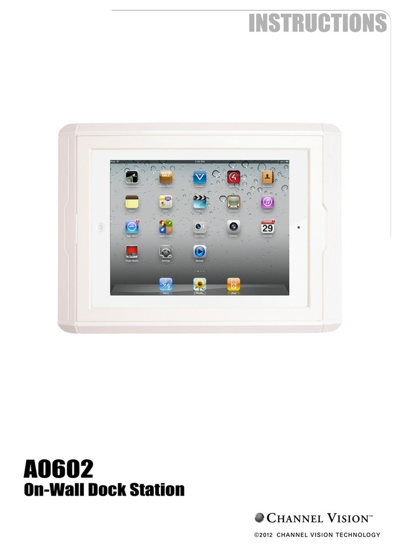
Channel Vision A0602 User manual

Channel Vision

Channel Vision A0602 User manual

Channel Vision A0316 User manual

Channel Vision

Channel Vision A0316 User manual

Channel Vision AB-315 User manual

Channel Vision

Channel Vision AB-315 User manual

Channel Vision AB-315 User manual

Channel Vision

Channel Vision AB-315 User manual

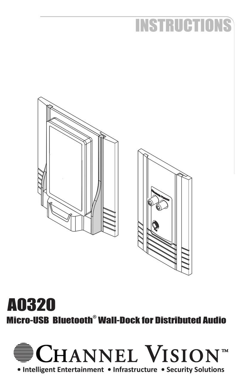
Channel Vision AO320 User manual

Channel Vision

Channel Vision AO320 User manual

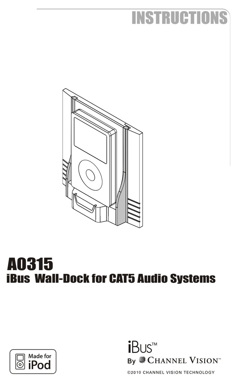
Channel Vision IBUS A0315 User manual

Channel Vision

Channel Vision IBUS A0315 User manual

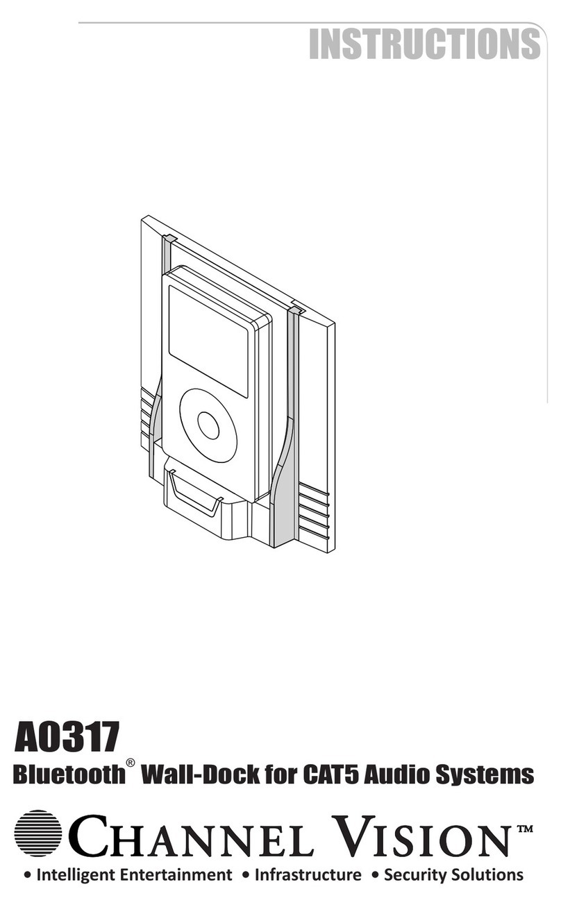
Channel Vision A0317 User manual

Channel Vision

Channel Vision A0317 User manual

Channel Vision iBus AB-311 User manual

Channel Vision

Channel Vision iBus AB-311 User manual

Channel Vision AB-313 User manual

Channel Vision

Channel Vision AB-313 User manual

Channel Vision iBus A0314 User manual

Channel Vision

Channel Vision iBus A0314 User manual

Channel Vision A0316 User manual

Channel Vision

Channel Vision A0316 User manual

Channel Vision A0314D User manual

Channel Vision

Channel Vision A0314D User manual

Channel Vision AB-318 User manual

Channel Vision

Channel Vision AB-318 User manual

Channel Vision IBUS A0315 User manual

Channel Vision

Channel Vision IBUS A0315 User manual

Channel Vision A0602 User manual

Channel Vision

Channel Vision A0602 User manual

Channel Vision iBus A0312 User manual

Channel Vision

Channel Vision iBus A0312 User manual

Channel Vision P-3036 User manual

Channel Vision

Channel Vision P-3036 User manual

Channel Vision A0318 User manual

Channel Vision

Channel Vision A0318 User manual

Popular Docking Station manuals by other brands

Kensington K32800WW quick start guide

Kensington

Kensington K32800WW quick start guide

Philips DC200/05 quick start

Philips

Philips DC200/05 quick start

Clarion NK1U Installation and wire connection manual
Clarion

Clarion NK1U Installation and wire connection manual
JVC 0397MKV*UN*SN instructions

JVC

JVC 0397MKV*UN*SN instructions

Lenovo USB-C Universal Business Dock user guide

Lenovo

Lenovo USB-C Universal Business Dock user guide

IBM ThinkPad Dock user guide

IBM

IBM ThinkPad Dock user guide

Philips DCB 2070 - user manual

Philips

Philips DCB 2070 - user manual

Icy Box IB-DK2108M-C manual

Icy Box

Icy Box IB-DK2108M-C manual

Lenovo ThinkPad OneLink Pro Dock user guide

Lenovo

Lenovo ThinkPad OneLink Pro Dock user guide

Philips DC199B/12 quick start guide

Philips

Philips DC199B/12 quick start guide

Cellofoam PERMAPORT XPRESS Assembly, installation and maintenance instructions
Cellofoam

Cellofoam PERMAPORT XPRESS Assembly, installation and maintenance instructions

Naxa NI-3107 owner's manual

Naxa

Naxa NI-3107 owner's manual

BENZING Express G2 DOC quick start guide

BENZING

BENZING Express G2 DOC quick start guide

Hawking H-DS20L user manual

Hawking

Hawking H-DS20L user manual

MainStation MS-D1 user guide
MainStation
MainStation MS-D1 user guide

Exsys EX-1222HM manual

Exsys

Exsys EX-1222HM manual

Hedson DRESTER RDX 8012 manual

Hedson

Hedson DRESTER RDX 8012 manual

Iluv i277 instruction manual

Iluv

Iluv i277 instruction manual

manuals.online logo
manuals.online logoBrands
  • About & Mission
  • Contact us
  • Privacy Policy
  • Terms and Conditions

Copyright 2025 Manuals.Online. All Rights Reserved.