Chapman MG Series User manual


Page 2
Contents
3Introduction
4HSE Information
8 Important Safety Information
Definitions
Safety Information
Transportation Safety
10 Description
Machine Identification
11 Implement Decals
12 Transporting & Lifting
12 Implement Layout
13 Operating Principles
Spring Tines (Optional)
Levelling Blades
Rear Roller (Optional)
16 Assembly
Drawbar Fitment
Tine Kit Fitment
Rear Roller Fitment
Attachment to Towing Vehicle
18 Adjustment
Working Depth
19 Grading Procedure
1Perimeter Grading
2Primary Grading
3Secondary Grading
21 Maintenance & Service
Tyre Pressure
Depth Adjustment Screw
Spring Tine Wear
Blade wear
22 Warranty
The Chapman Warranty
Warranty Conditions
Extended Warranty
Extended Warranty Conditions
Transfer of Warranty
24 Specification
25 CE Declaration

Page 3
Introduction
By purchasing a Chapman Machinery MG250 Manége Grader you have purchased
a product designed to give a first class finish and also have a long life span, if used
and maintained correctly as detailed in this manual.
A variety of options are available from the factory, and many of these are also suit-
able for retro-fitment if your requirements change, or you purchase this machine
used, and wish to use a different set-up. We are more than happy to offer advice &
support throughout the lifetime of the machine.
This manual also contains important Health & Safety Executive information and
guidelines.
NOTICE:
THIS MANUAL MUST BE HANDED TO THE OPERATOR BEFORE USE. THE OPERATOR
MUST UNDERSTAND FULLY THE CONTENT OF THIS HANDBOOK BEFORE USING THE
MACHINE FOR THE FIRST TIME. OF THE IMPLEMENT IS RESOLD, THIS MANUAL
MUST ACCOMPANY THE MACHINE.
Note:
The information contained in this manual is correct at the time of going to press.
However, in the course of development, changes in specification are inevitable.
Should you find the information given differs from your machine, please
contact Chapman Machinery direct for any after sales advice.
Chapman Machinery Ltd
Hele Barton
Week St.
Mary
Holsworthy
Devon
EX22 6XR
Tel:01288 308149

Page 4
HSE information sheet
Safe use of all-terrain vehicles (ATVs)
in agriculture and forestry
HSE Information
Agriculture Information Sheet No 33
Introduction
This information sheet gives advice on the safe use of
ATVs. It covers the two main types used in off-road
working in agriculture and forestry, which are:
●
sit-astride ATVs: any motorised vehicle designed
to travel on four low-pressure tyres on unpaved
surfaces, with a seat designed to be straddled by
the operator and handlebars for steering control.
They are intended to be used by a single operator
with no passenger. However, this type also
includes ATVs intended for use by a single
operator, but with a special seat for a passenger
behind the operator. These vehicles are generally
called ATVs in agriculture, quad bikes in leisure
use and all-terrain cycles (ATCs) in forestry;
●
sit-in machines: side-by-side mini-utility vehicles,
usually with a steering wheel, where the driver sits
in a conventional seat and there is generally
seating for one or more passengers. These are
often called ATVs in both agriculture andforestry.
The ATVs covered by this sheet are those designed for
off-road use only. However, agricultural, horticultural
and forestry users can register an ATV as a ʻLight
agricultural vehicleʼ for limited on-road use in
connection with their business (see ʻRoad useʼ).
Accidents
Both types of machine are designed to cope with a
wide variety of terrain types, including steep slopes, but
if used outside their safe operating parameters they
can very rapidly become unstable. This is why most
ATV accidents involveoverturning.
On average, two people die each year in ATV
accidents. Non-fatal accidents are estimated to amount
to over 1000 serious injuries per year. The underlying
causes of accidents were usually one or more of the
following:
●
lack of structured training and/orexperience;
●
incorrect/lack of protectiveclothing;
●
excessive speed;
●
carrying a passenger or an unbalancedload;
●
tipping on a bank, ditch, rut or bump;
●
a steep slope combined with other factors, eg
ground or load conditions;
●
towing excessive loads with unbrakedequipment.
Route planning and stability
Most accidents with these machines have occurred
where they have either been driven on new routes over
steep ground for the first time, or have been carrying or
dragging destabilizing loads. When travelling over
rough terrain, get to know your own ground and stick to
planned routes where possible. Walk new routes if
necessary to check for hidden obstructions. Allow for
changes in ground conditions and for the destabilizing
effect of loads orattachments.
Sit-astride ATVs (quad bikes/ATCs)
REMEMBER - GET PROPERLY TRAINED AND
ALWAYS WEAR HEAD PROTECTION
Training
Under the Provision and Use of Work Equipment
Regulations 1998 (PUWER), there is a legal
requirement for employers to provide adequate training,
and to ensure that only employees who have received
appropriate training in their safe use, including the use
of any towed equipment or attachments, are permitted
to ride ATVs. The same requirements apply to the self-
employed. HSE regards training provided by
recognized training providers as being adequate for the
purposes of PUWER.
You can get details of suitable training courses from
franchised ATV dealers, manufacturers’ websites, EASI
(European ATV Safety Institute), the Forestry
Commission and Lantra Awards. Training is also
available from agricultural trainers and colleges
accredited by these bodies.

Page 5
Protective clothing
More than half of all ATV riders have been thrown off at
some time. As these machines are not fitted with either
a cab or roll bar, your only protection is what you wear.
●
Head protection is vital. The majority of ATV
fatalities in the UK in the last ten years have been
caused by head injuries. Nobody who died from
head injuries was wearing a helmet. Helmets
would certainly have prevented most, if not all, the
deaths. You should always wear a helmet when
riding an ATV. Helmet types suitable for ATV
operations, depending on the circumstances, are
motorcycle helmets to BS 6658:1985 or UN ECE
regulation 22.05, equestrian helmets to BS EN
1384:1997, including specialist ATV helmets, cycle
helmets to BS EN 1078:1997 and mountaineering
helmets to BS EN 12492:2000. All helmets should
have a chinstrap and be capable of being used
with suitable eye protection. The type of helmet
chosen should be based on an assessment of the
circumstances in which the ATVwill be used, eg
the types of surface travelled over and anticipated
speeds. The harder the surface and higher the
speed the greater the degree of protection
needed. NB: Forestry helmets and industrial
hard hats are not acceptable for any ATV
operations.
●
Wear clothing that is strong and covers your arms
and legs. Gloves are useful for protection and to
keep hands warm in cold weather for good control
of the ATV.Wear sturdy, ankle-covering footwear,
eg boots or wellingtons that are strong, supportive
and have good wet grip.
●
Protect your eyes from insects and branches with
either a visor or goggles.
Passengers
Never carry a passenger on a sit-astride ATV unless
it has been designed for, and is suitable for, that
purpose. The long seat is for operators to shift their
body weight backwards and forwards for different slope
conditions, not for carrying passengers. Passengers on
specially adapted ATVs must wear a safety helmet. Do
not carry a passenger in a trailer behind an ATV as any
movement can make the machine unstable, particularly
with independent rear suspension and trailers with
axles wider than the ATV.
Safety checks and maintenance
Off-road use is especially harsh on equipment so it is
essential to carry out safety checks and maintenance in
accordance with the manufacturerʼs recommendations.
In particular, pre-ride safety checks should always
include:
●
tyre pressures. These are low, eg around 2-7 psi,
so even a 1 psi (0.07 kg/cm2) difference in
pressure can cause vehicle control problems.
Use a gauge that is designed for measuring and
displaying low pressures –usually supplied with
the ATV;
●
brakes and throttle. Check that the brakes give a
safe straight stop and that the throttle operates
smoothly in all steering positions. Brakes can
have a relatively short life in farming or forestry
environments and need frequent cleaning, regular
adjustment and propermaintenance.
Safe driving methods
ATVs are rider-active machines, so rider positioning is
vital to operate them correctly. The position of the rider
on the machine needs to be changed depending on the
terrain and motion. Riders must have the ability to
move and balance the momentum of the ATV with their
own body weight. Plan routes (and review the plan if
the route is used regularly) to assess risks.
The following advice is no substitute for formal
training.
●
Most ATVs have no differential and so do not
handle in the same way as other machines. This
means that when you turn, the ATV tries to keep
going in a straight line.
●
When cornering on an ATV with no differential or
with the differential lock engaged, where your
body weight needs to be positioned depends on
how sharp the corner is and on how fast you are
going. Correct body position allows you to transfer
weight to the outside of the turn through the
footrests while maintaining balance with the torso.
This lets the inside wheels skid slightly allowing
the ATV to make the turn properly.
●
Youmust understand how the transmission
system of your machine will affect engine braking
for both riding, and recovery of stalled ATVs, on
slopes.
●
When riding across a slope, keep your weight on
the uphill side of the ATV.
●
When going downhill, slide your weight
backwards, select a low gear and use engine
braking, reducing the need to use the brakes.
●
When going uphill, it is important to review the
route before starting the climb. Move your weight
forwards and maintain a steady speed. It is
important to shift your body weight forwards as
much as possible. If necessary stand up and lean
forward, keeping both feet on the footrests at all
times and always maintain momentum.
●
Avoid sudden increases in speed, as this is a
common cause of rearward overturning accidents,
even from a standing start on flat ground where
there is good grip.

Page 6
●
Never put your foot onto the ground to
stabilise an ATV when riding, but shift your
weight across the ATV away from the imbalance.
●
Always read the owner’s manual.
Trailed equipment and loads
Ensure all riders know the manufacturer’s
recommended towing capacity and drawbar loading
limit. Always operate within these requirements.
Remember that your ability to control the ATV by your
body movements will be considerably reduced when
carrying a load or towing a trailer.
●
When selecting trailed equipment look for:
-
over-run brakes;
-
a swivel hitch drawbar;
-
bead lock rims on wheels;
-
a low center of gravity and a wide wheel
track;
-
a long drawbar; and
-
attachment points for securing a load.
●
Check the weight ratio between your ATV and its
trailed load. This needs to be assessed for each
operation. As a general guide, on level ground,
braked trailed equipment can be a maximum of
four times the unladen weight of the ATV.For
unbraked trailed equipment the maximum should
be twice the unladen weight. These loads should
be reduced when working on slopes, uneven
ground or poor surface conditions. Follow the
manufacturer’s advice for your particular machine.
●
Weight transfer is also important. Stability and
resistance to jack-knifing is improved if some load
is transferred onto the ATVʼs drawbar.
Approximately 10% of the gross weight of the
loaded trailer is recommended, but this should not
exceed the manufacturer’s drawbar loading limit.
Remember that weight transfer can change
dramatically when you start going up or down hill.
●
When selecting mounted equipment, make sure it
is within the manufacturer’s approved weight limit,
with a low center of gravity, and controls which are
easy to operate but do not create a hazard. Where
equipment is added to one end of the machine,
add ballast at the other end to maintain stability.
●
Loads carried on racks must be well secured, e.g.
with ratchet straps, and be evenly balanced
between the front and rear, except where they are
deliberately altered to aid stability when going up
or down a slope.
●
Only tow a load from the hitch point. Loads towed
from other points such as the rear rack have
caused sudden rear overturning even on slight
slopes or with slight acceleration. Ropes or chains
should not be used to drag a load where they can
become caught on a wheel. This may lead to
entanglement with the brake cable, causing
unexpectedbraking.
Using sprayers
●
Pesticides should be used in accordance with the
Code of Practice for using plant protection
products published by Defra. (Available from
Defra Publications, ADMAIL 6000, London SW1A
2XX Tel: 08459 556000.)
●
Sprayers should meet the requirements of BS EN
907 and be fitted with an induction hopper unless
the filling point is less than 1.5 m from the ground
and within 0.3 m from the edge of the sprayer. A
separate clean water tank for washing must be
provided containing at least 15 litres of clean
water and a tap that allows the water to run
without being continuouslypressed.
●
When buying a sprayer look for a low center of
gravity and internal baffles to reduce liquid surge
to improve stability when turning on slopes.
●
ATVs should only be used with rear-mounted
spray booms or other equipment that reduces the
risk of pesticide exposure to the operator.
●
Do not hold a spraying lance while riding your
ATV,as two hands are needed for safe control.
Accessories
Beware of the potential dangers of accessories which
are not approved by manufacturers, e.g. home-made
gun racks and boxes. Either use accessories
supplied/approved by manufacturers or seek their
advice as to the suitability of those sourced elsewhere.
Any weight added above the center of gravity will
decrease the ATVʼs stability.
Children
●
Never carry a child as a passenger. It is illegal and
will reduce your ability to control the ATV.
●
Children under 13 are prohibited from using an
ATV at work. Over 13 they should only ride ATVs
of an appropriate size and power, after formal
training on a low-power ATV.
●
Check and adhere to the manufacturer’s
minimum age recommendations for your ATV.
The ratio of a child’s weight to that of the ATVis
significant, as weight transfer is the key to safe
handling.
●
Always refer to the owner’s manual and warning
labels on the machine.
Roll bars, lap straps and weather cabs
●
Roll bars are not recommended for sit-astride
ATVs. Research has shown that they are more
likely to increase injuries by obstructing the rider,
either when thrown off or when jumping off during
an overturn. This causes the rider to fall to the
ground alongside the ATV and increases the
likelihood of injury. PUWER does not require roll
bars where they would increase the overall risk.

Page 7
●
Lap straps should not be fitted. They prevent
active riding and would be potentially lethal
without a full cab or roll cage.
●
Weather cabs restrict a rider’s ability to jump clear
in an overturn. The rider is likely to be crushed
within the cab unless it is strong enough to
withstand the forces involved. Carefully assess the
risks for your particular conditions of use before
fitting any such structure and consult the
manufacturer forinformation.
Road use
For road use, ATVs and trailers have to comply with the
Road Vehicles Construction and Use Regulations 1986
(as amended) and the Road Vehicles Lighting
Regulations 1989 (both enforced by the police) and be
licensed in the appropriate class. They do not require
an MOT and the maximum permitted speed is 20 mph.
The minimum age for drivers is 17 and they need a
Category B licence.
Sit-in ATVs
Sit-in ATVs include the Mule, Rhino, Argocat, Scot-
Track, Gator, Ranger, Hiler, Goblin and other similar
machines. They all have conventional sit-in seats and
the driver does not use weight transfer to steer or
control stability, although load balance is important in
this respect. They range from machines designed for
purely rough terrain to utility vehicles, which are also
commonly used fully off-road.
Training
The legal requirements for training are the same as for
the sit-astride ATVs. You should request advice on
training from your suppliers, the training providers
previously mentioned or, for forestry operations, from
the Forestry Commission.
Rollover protection and seat belts
The requirements for these machines are quite different
to those of sit-astride ATVs.
●
Where there is a risk of the machine rolling over,
PUWER requires an employer to fit some device
to protect employees (the self-employed have the
same duty to themselves). This would normally be
a cab, rollover frame or roll bar. Such a structure
could either be provided as part of the original
machine or, if added afterwards, should be CE
marked and approved by a recognized test body.
●
Restraining devices such as seat belts should be
fitted and worn by the driver and passengers
where a roll bar or cab is fitted.
●
Where a machine is amphibious and used on
deep water as opposed to marshland, then the
seat restraints (and possibly roll frame) could
increase the overall risk rather than reduce it. In
this case, do not use seat restraints while on the
water. Assess the risk from the roll frame
according to its design and the likelihood of
trapping the occupants if the machine should sink.
●
If there is a risk of overturning, employees at work
who are carried in the rear of sit-in ATVs should
be protected by rollover protection and seat
restraints.
●
Children should only be carried in these vehicles if
they are in a passenger seat and wearing a
properly designed and fitted seatbelt.
Parking
If you have to park on a slope, always park across it
unless it is too steep. Accidents have occurred where
machines have run down slopes because of poor brake
maintenance or application, particularly while they are
being loaded, and movement or the increase in weight
sets the machine into motion.
Further information
HSE priced and free publications are available by mail
order from HSE Books, PO Box 1999, Sudbury, Suffolk
CO10 2WA Tel: 01787 881165 Fax: 01787 313995
Website: www.hsebooks.co.uk (HSE pricedpublications
are also available from bookshops and free leaflets can
be downloaded from HSEʼs website: www.hse.gov.uk.)
For information about health and safety ring HSEʼs
Infoline Tel: 0845 345 0055 Fax: 0845 408 9566
Text phone: 0845 408 9577 e-mail:
hse.infoline@natbrit.com or write to HSE Information
Services, CaerphillyBusiness Park, Caerphilly CF83 3GG.
© Crown copyright This publication may be freely
reproduced, except for advertising, endorsement or
commercial purposes. First published 05/99. Please
acknowledge the source as HSE.
This leaflet contains notes on good practice which are not
compulsory but which you may find helpful in considering
what you need to do.

Page 8
Important Safety Information
Always read this manual before fitting or operating the machine –whenever
any doubt exists contact your dealer or the Chapman Machinery Service
Department for advice and assistance.
Use only Chapman Genuine Service Parts on Chapman Machinery equipment and at-
tachments.
Ensure to:
-Maintain the machine correctly as per this manual
-Ensure all nuts, bolts and fixings are secure before first use, and check at
-regular intervals during operation
-Avoid excessively steep ground or adverse land conditions likely to damage
the machine
-Follow all recommended service instructions
-Attach to a vehicle suitable to the purpose
DEFINITIONS
The following definitions apply throughout this manual:
WARNING
An operating procedure, technique etc., which –
can result in personal injury or loss of life if not observed carefully.
CAUTION
An operating procedure, technique etc., which –
can result in damage to either machine or equipment if not observed carefully.
NOTE
An operating procedure, technique etc., which –
is considered essential to emphasis.
LEFT & RIGHT HAND
This term is applicable to the machine when attached to the towing vehicle and is
viewed from the rear –this also applies to tractor references.

Page 9
Safety Information
-
Do not operate this equipment unless you have studied this manual in full
-
Only use this machine for its designated task - improper use is both highly
dangerous and damaging to machine components
-
Both operators & maintenance fitters should be familiar with the machine and
fully aware of dangers surrounding improper use or incorrect repairs
-
Before starting, carry out a visual check on both machine & towing vehicle as re-
grads functionality, road safety & accident prevention rules
-
During checks or repairs, ensure the machine cannot be started or moved by other
persons by mistake
-
Never wear loose clothing which could get caught in rotating equipment
-
Never carry passengers on the towing vehicle
-
Do not stand near the machine when operating
-
Damaged or missing safety decals must be replaced immediately
-
Do not operate whilst under the influence of drugs, alcohol or similar substances
-
Exceed maximum towing speed of 10mph
-
Leave the machine unattended where animals could come into contact with it
Transportation Safety
-
When transporting, especially over rough ground, reduce speed to prevent damage
to machine.
-
This machine is not road legel. DO NOT tow on public highways

Page 10
Description
The MG range of equipment are non-powered machines designed to be towed by a
suitable vehicle such as a 4x4, UTV or ideally an ATV.
Designed around a base machine suitable for simple pure sand areas, options and
accessories can be added quickly and easily to enable the MG250 to tackle almost
any arena surface type.
With a 2.4m working width, you can spend less time maintaining your arena and
more time actually using it. Built from heavy duty box section steel, with easily re-
place able wearing parts, and top quality zinc primer & powder coated finish, the
MG250 will withstand years of use.
These machines should however only be used to perform tasks for which they were
designed - use of the machine for any other function may be both dangerous to per-
sons, and potentially damaging to components. Use of the machine beyond the stated
usage may invalidate any applicable warranty, as well as being potential in breach of
applicable safety regulations.
Identification
Each machine is fitted with a serial plate which details the following:
1. Model No.
2. Date of Manufacture (DOM)
3. Serial No.
4. Mass
When enquiring regarding spares or additional equipment, ensure you have this infor-
mation to hand.

Page 11
Implement Decals
If your implement does not contain all of the decals shown below, please contact
Chapman Engineering for replacement decals before use.
*Carefully read operators manual before handling this machine. Observe instructions
and safety rules when operating.
*Never reach into the crushing danger area as long as parts may move.

Page 12
Transporting & Lifting
Ensure that the vehicle used to transport or operate the Ménage Grader has adequate
lifting and towing capacity. Follow towing vehicle manufacturer capacity guidelines.
When lifting or moving the Ménage Grader for transport or delivery purposes, ensure
to locate the lifting straps evenly across the frame to take the implement weight safe-
ly. When transporting the product in assembled form ensure it is adequately strapped
down to prevent movement during transportation, and ensure the transportation
complies with all applicable highway laws.
Under no circumstances should the machine be towed on public highways.
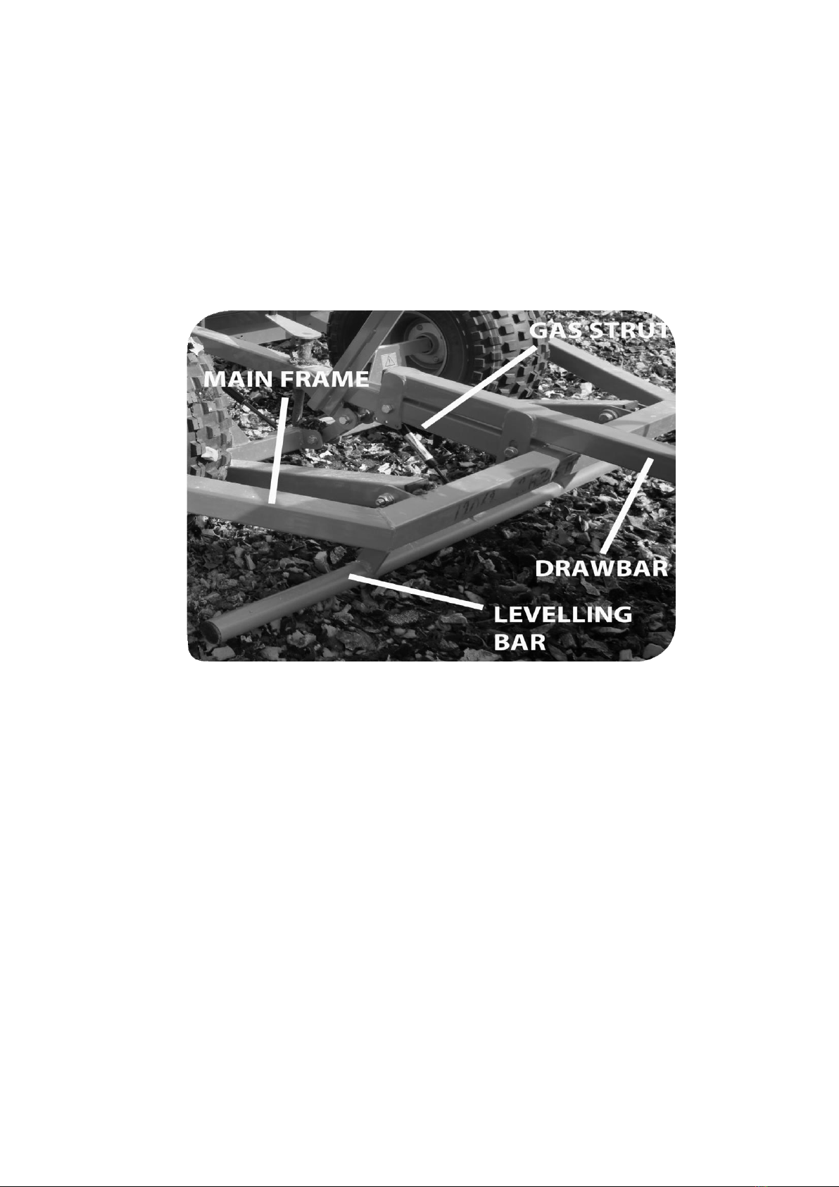
Implement Layout

Page 13
Operating Principles
The grader has three main operating principles, depending on optional accessories fit-
ted:
Spring Tines
The spring tines agitate the surface, causing stirring and flicking of the arena mate-
rial, which fills in divots and levels surface lumps. This is an essential component of
good surface maintenance for rubber crumb and fibre-stabilised sand surfaces, but is
also highly useful for plain sand surfaces.
The working depth of the tines is recommended to be 45mm for most surfaces (the
middle bolt holes). Greater tine depth will mean greater surface lift, giving a ‘softer’
resulting ride, however, a greater static load is placed on the towing machine, so only
large towing machines (large ATVs, UTVs etc.) will have adequate traction to work to
design spec.
The tines are attached by an elegant single-bolt mechanism, to facilitate quick and
easy replacement should one fail, or when the tines wear out. Replacement tines are
easy to fit, and are available for a very reasonable price direct from Chapman Engin-
neering.
Levelling Blades
The rear levelling blades smooth the surface and move material forwards to fill in
divots and give a level arena. The effect of the blades passing over the material then
firms the surface lightly to give a consistent surface. The blades feature a special an-
glad profile to more effectively draw material forward and level it.
The use of the perimeter blade is twofold:
-In the parallel position the blade works to level and consolidate across the entire
width of the machine. This is used for the bulk of the arena grading. The machine
should only be towed to/from the arena with the blade in this position.
-In the angled position the blade draws material towards the center of the machine.
This is used primarily to draw material in from the edge boards, and is especially
useful when circular schooling work has been done, as it can quickly draw in and
level the banking that inevitably occurs. The two edge roller wheels prevents damage
to the edge boards whilst ensuring the grader blade can operate right up to the edge
boards. For arenas with low kick boards, an optional low-height roller wheel can be
fitted - contact your distributor for details.

Page 14
Rear Roller (Optional)
The rear is an optional fitment specifically designed for use with advanced surfaces
such as CLOPF, Turf float and other fibre-stabilised surfaces. The roller works well on
any arena type, consolidating and ‘firming’ the surface, to give a true one-pass finish
for busy liveries & riding schools. A useful attachment which save you the expense of
a separate roller & the hassle of changing implements regularly.
There are three operating modes:
-
No roller. This mode is used when drawing material in from the edge boards, or
when a firmed surface is not desired. The machine locks in this position with the use
of two clips, for transportation & storage. *Note: This places a considerable negative
load on the ball hitch. TAKE CARE when unhitching the machine in this configuration.
-
Following roller. This mode is used so that the roller is following both the spring
tines & blades. This is the primary mode of use, giving an agitated, level and firmed
surface in one pass.

Page 15
Rear Roller Notice:
The rear roller is, by the very essence of its purpose for rolling & consolidating the
surface, HEAVY. The design of the roller mounting arrangement is such that the
roller automatically lifts off the surface when the machine is changed from “work
mode” to “transport mode”.
A gas strut is fitted as standard to ease lifting of the roller, however a reasonable
amount of force is still required in order to do so. An optional electric lift and depth
control system can be fitted, please contact your Distributor for details.
It is recommended NOT to attempt to lift the machine out of work mode with the
roller set in the upright position, as shown by the image below, and to instead raise
the roller to this position after lifting the machine out of work.
The gas strut does a lot of work when lifting the roller, and therefore it is essential
that this is maintained. If the gas strut becomes worn, or the roller becomes heavy to
lift, replacement is quick and simple.
Page 16
Assembly
Drawbar Fitment & Adjustment
With the machine on the ground raise the transport lever so that the machine is in
‘work’ position. With the supplied bolts, attach the drawbar through the two fixing
holes located on the frame and tighten to hand-tight only. Attach the gas strut to the
mounting brcket using the fixings supplied. For most surfaces attach the gas strut to
the middle attachment point.
Attach the grader to the towing machine, and adjust drawbar angle until the main
frame of the machine runs approximately parallel with the ground when in working
mode. Tighten mount bolts firmly before use, and CHECK TIGHTNESS OF ALL BOLTS
after first use.
Tine Depth Adjustment
It is recommended that the middle tine setting is used for the initial fitment, giving
a tine working depth of approximately 45mm below the surface.
Adjust the depth of the tines by moving the main bar up or down on the mounting
brackets. Ensure the mounting bolts are suitably tight after adjusting.

Page 17
Rear Roller Fitment & Adjustment
Safety Notice
CAUTION - REAR ROLLER IS HEAVY
Lower the machine to the ground by engaging ‘work’ mode. maneuver the roller at
the rear of the machine so that the mounting holes align. Attach the roller using the
two supplied M12 x 60mm bolts, washers and nuts utilizing the rearmost holes, as
shown below.
Attachment to Towing Vehicle
Any vehicle with a 50mm ball hitch can tow the machine. Ensure the hitch is securely
fastened, and the machine is in transportation mode (transport lever raised) before
moving off.
The recommended towing vehicle for this grader is either an ATV or UTV or 4x4 due
to the optimum balance between weight, maneuverability and traction.
Safety Notice
ATVs 250cc or under are not recommended for machines with tine kits and/or rear
rollers fitted due to tractive limitations. Some small ATVʼs may be ok, depending on
tyre condition and towing capacity. Four-wheel drive (if applicable) should be engaged
at all times.

Page 18
Adjustment
Working Depth
Note: Ensure both tyres operate under the same working pressure (Recommended
4-6psi, 8psi for graders equipped with rear roller)
-Move the grader to the arena that is suitable for test grading
-Ensure the perimeter blade is in the parallel position
-Lower the machine to the ground by engaging working position. Screw the working
height adjustment down so that it contacts the axle crossbar. Lift the machine of the
ground by engaging transport mode, and screw the adjuster down a further rotation.
This provides a good basis to begin with.
-Move forward slowly to assess the grading depth, and adjust as necessary.
-An element of trial-and-error is required to find the best settings for each arena,
and the optimum working depth will change through the year due to variables such
as surface temperature, water content etc.
-Once you find a good depth setting for your arena, the screw adjuster can be left
in this position so that you can easily grade the arena next time with minimal adjust-
ment.
NOTE: The transport lever should ALWAYS be raised away from the working position
to adjust the working depth adjustment screw to prevent unnecessary cosmetic dam-
age to the axle assembly

Page 19
Grading Procedure
There are three main parts to the grading process:
1Perimeter Grading
The edge material of the arena should always be levelled first upon entering the site,
and is extremely important in preventing the material becoming banked around the
perimeter of the arena.

Page 20
How to use the perimeter blade on the MG250 (Sept 2016 onwards)
1. Your machine will have the perimeter blade attached to the main frame on the
right hand side as shown below.
2. With the machine in transport mode remove steel pin and turn the blade to a 90-
degree angle (see below) making sure the pin holes are aligned. The perimeter
blade can also be used on the left hand side of the machine.
3. Slide the pin back into place, ensuring the blade is secure.
This manual suits for next models
1
Table of contents
Other Chapman Farm Equipment manuals


Popular Farm Equipment manuals by other brands

Redexim
Redexim Verti-Drain 1513 User manual and parts book

BIG BALE
BIG BALE Transtacker Standard Operation and maintenance manual

USC
USC LPV Series Operator's manual

KUHN
KUHN GA 8001 H Assembly and operators manual

KUHN
KUHN FC 4000 R Owner's/operator's manual

Rabe
Rabe KORMORAN PL V 180 operating instructions


