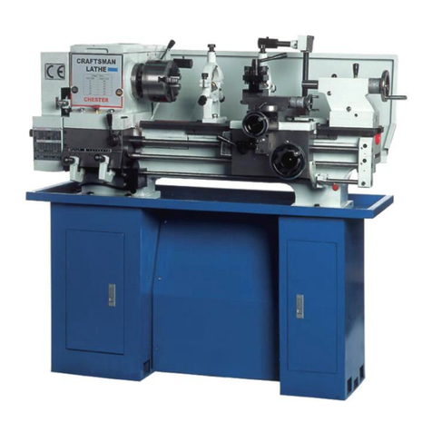
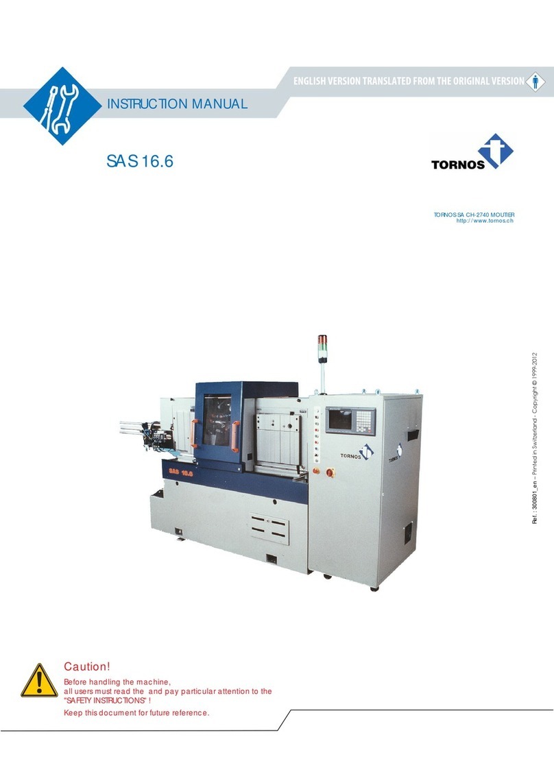
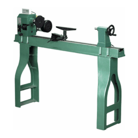
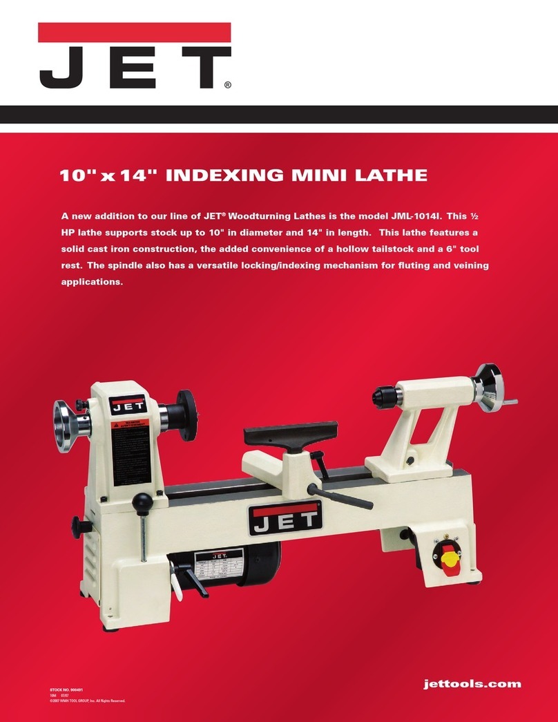
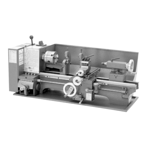
CHESTER 920 User manual

920 Lathe
Manual
Chester UK Ltd
Clwyd Close
Hawarden Industrial Park
Hawarden
Chester
CH5 3PZ
Tel: 01244 531631
Email: [email protected]
www.chestermachinetools.com

Safety rules for Machine Tools
Warning: Do not attempt to operate until you have read thoroughly and completely understand all instructions
contained within this manual. Failure to comply can result in accidents involving fire, electric shock, or serious
personal injury.
Maintain owner’s manual and review frequently for continued safe operation.
1. Know your machine tool. For your own safety, read the manual carefully. Learn it’s application and limitations,
as well as the specific potential hazards for this machine.
2. Guard against electrical shock by preventing body contact with grounded surfaces. For example; Pipes,
radiators, refrigerator enclosures.
3. Keep guards in place and in working order.
4. Remove adjusting keys and wrenches. Make a regular habit of checking that keys and wrenches are removed
from the machine tool before turning it on.
5. Keep work area clean. Cluttered benches and work areas can cause accidents.
6. Don’t use in any dangerous environments. Don’t use machine tool in damp or wet locations or expose them to
rain. Keep work area well illuminated.
7. Keep children away. Anyone should be kept a safe distance away from the work area.
8. Make workshop child proof. Install padlocks, and switches, or remove starter keys from the area.
9. Don’t force machine tool. Your machine will work better and safer.
10. Use the right tool(s). Don’t force tool(s) or attachment(s) to do a job which they aren’t designed for.
11. Wear proper apparel. Don’t wear any loose clothing, gloves, jewellery, or ties which could get caught in
moving parts. Non slip footwear is recommended. Wear protective hair coverings for long hair.
12. Always use safety glasses. Face or dust masks should also be used if cutting operation is dusty. Everyday
glasses only have impact-resistant lenses, these are not suitable for safety glasses.
13. Secure work. Use clamps or a vice to hold work when practical. This is safer than using your hands and frees
them to operate the machine.
14. Don’t overreach. Keep proper footing and balance at all times.
15. Maintain machine tool(s) in top condition. Keep tools sharp and clean for best and safest performance. Follow
instructions for lubricating
16. Disconnect tools from power source. Before servicing, and when changing accessories, when mounting, or re-
mounting motor.
17. Avoid accidental starting. Make sure switch is in the “off” position before plugging in.
18. Use recommended accessories. Consult the owner’s manual for recommended accessories. Use of improper
accessories may be hazardous.
19. Never stand on a tool. Serious injury could occur if the tool is tipped or if the cutting tool is unintentionally
contacted.
20. Check damaged parts. Before further use of the machine tool, guard, or any other part that is damaged should
be checked carefully to ensure that it will operate properly and perform it’s intended function. Check for
alignment of moving parts, binding of moving parts, breakage of parts, mounting and any other conditions that
may affect it’s operation. A guard or any other part that is damaged should be properly repaired or replaced.
21. Direction of feed. Feed work into a blade or cutter against the direction of rotation of the blade or cutter only.
22. Never leave tool running unattended. Turn the power off. Don’t leave the machine tool until it comes to a
complete stop.
WEARYOUR

Safety rules for lathes
Safety is a combination of operator common sense and alterness at all times when the lathe is being used. Study
these safety rules and general safety rules before operating and retain for future use.
1. Wear eye protection (ANSI approved)
2. Never attempt any operation or adjustment if procedure is not understood.
3. Keep fingers away from revolving parts and cutting tools whilst in operation.
4. Never force cutting action.
5. Never perform an abnormal or little used operation without study and use of adequate blocks, jigs, stops,
fixtures etc.
6. Use of shop manual such as “Machinery’s Handbook” or similar is recommended for cutting speeds, feeds,
and operation detail.
7. Do not remove drive cover whilst machine is in operation. Make sure it is always closed.
8. Always remove chuck key, even when the machine is not in operation.
9. Do not attempt to adjust or remove tools when in operation.
10. Always keep cutters sharp.
11. Never use in an explosive atmosphere or where a spark could ignite a fire.
12. Always use identical replacement parts when servicing.
Warning: Do allow familiarity (gained from frequent use of your lathe) to become commonplace. A careless fraction of
a second could allow for severe injury.

Index
Standard Equipment …………………………………………………………………………………………………. 5
Technical Data ………………………………………………………………………………………………………... 5
Setting up and preparing for operation of the machine ………………………………………………………….. 6
General description …………………………………………………………………………………………………... 7
Lathe bed ……………………………………………………………………………………………………………… 7
Headstock ……………………………………………………………………………………………………………… 7
Slides …………………………………………………………………………………………………………………... 8
Apron …………………………………………………………………………………………………………………... 8
Tailstock ……………………………………………………………………………………………………………..…. 9
Leadscrew …………………………………………………………………………………………………………… 9
Gear box ………………………………………………………………………………………………………………. 9
Drive and electrical equipment …………………………………………………………………………………….. 9
Controls ………………………………………………………………………………………………………………. 10
Working with the lathe ………………………………………………………………………………………………. 11
Setting the turning tool ………………………………………………………………………………………………..11
Manual turning …………………………………………………………………………………………………….….. 11
Longitudinal turning with auto-feed ………………………………………………………………………………… 11
Taper turning using tailstock set-over ……………………………………………………………………………… 12
Taper turning by setting the top slide ………………………………………………………………………….…… 12
Turning between centres ……………………………………………………………………………………………. 12
Screw cutting ………………………………………………………………………………………………………….. 13
Example of mounting the gear wheels …………………………………………………………………………….. 13
Slipping clutch ………………………………………………………………………………………………………… 13
Thread cutting table …………………………………………………………………………………………………. 14
Lathe accessories ……………………………………………………………………………………………………. 15
Universal lathe chuck, 3 or 4 jaw design …………………………………………………………………………… 15
4 Jaw Independent chuck ………………………………………………………………………………………….… 15
Drill chuck ……………………………………………………………………………………………………………… 15
Morse taper arbor …………………………………………………………………………………………………….. 15
Live centre ………………………………………………………………………………………………………………15
Centre steady rest …………………………………………………………………………………………………..… 16
Travelling steady rest …………………………………………………………………………………………………. 16
Setting the steady rest …………………………………………………………………………………………………16
Tool post ………………………………………………………………………………………………………………... 17
4-Way Tool post ……………………………………………………………………………………………………...… 17
Chip guard ……………………………………………………………………………………………………………... 18
Gear change lathe ……………………………………………………………………………………………………… 18
Cabinet stand …………………………………………………………………………………………………………… 18
Bearings and slide adjustment …………………………………………………………………………………………19
Adjustment of main spindle bearings ………………………………………………………………………………… 19
Adjustment of cross and top slides …………………………………………………………………………………… 19
Adjustment of feed screw end float …………………………………………………………………………………… 19
Feed screw backlash adjustment……………………………………………………………………………………… 19
Cross slide spindle ……………………………………………………………………………………………………… 19
Top slide spindle backlash adjustment ………………………………………………………………………….…… 20
Adjustment of half-nut guide …………………………………………………………………………………………… 20
Adjustment of leadscrew backlash ………………………………………………………………………………….… 20
Replacing the shear pin in the leadscrew ………………………………………………………………………….…. 20
Re-position the v-belt …………………………………………………………………………………………………... 21
Lubrication plan ………………………………………………………………………………………………………….. 22
Head stock ………………………………………………………………………………………………………………. 23
Drive ……………………………………………………………………………………………………………………… 25
Tensioning roller ………………………………………………………………………………………………………… 27
Quadrant ………………………………………………………………………………………………………………… 29
Lathe bed ……………………………………………………………………………………………………………..… 31
Gear box ………………………………………………………………………………………………………………… 33
Apron ……………………………………………………………………………………………………………………. 35
Saddle and cross slide ………………………………………………………………………………………………… 39
Drive …………………………………………………………………………………………………………………….. 41
Topslide …………………………………………………………………………………………………………………. 42
Tailstock …………………………………………………………………………………………………………………. 44
Travelling steady rest …………………………………………………………………………………………………. . 46
Wiring diagram ………………………………………………………………………………………………………….. 48

Standard Equipment
The following items are included with this machine:
• Bed
• Headstock
• Saddle, Cross, Top-Slides
• Tailstock
• Reduction Gear
• Automatic feed with quadrant and 6 change wheels
• Driving pin with nut
• Driver
• MT2 & MT3 Centres
• Single tool holder (clamp)
• Electrical equipment with motor etc..
• Service manual
Technical specifications
Centre Height
115mm (4-1/2”)
Distance between centres
500mm (20”)
Max. dia over slide
68mm (2-5/8”)
Required floor space
950 x 500mm (37-1/2” x 20”)
Weight
95kg (210lbs)
Headstock spindle nose
MT3
Hollow spindle (inside dia.)
20mm (3/4”)
Spindle bearings
2 adjustable precision taper roller bearings #32007
Spindle speeds
130, 300, 400, 600, 1000, 2000 rev/min (60Hz)
100, 250, 350, 500, 900, 1800 rev/min (50Hz)
Feed with Leadscrew
0.127mm/rev (0.005”/rev)
0.177mm/rev (0.006”/rev)
Thread pitches
Metric: 0.5-3mm
Imperial: 8-56 thread/inch
Tailstock
Spindle dia. 26mm (1”)
Spindle travel 40mm (1-5/8”)
MT2
Motor
Speed: 1720rpm (60Hz), 1500 (50Hz)
Capacity: 3/4hp

Setting up and preparing for operation
To avoid twisting of the bed, care should be taken to the location where the machine is bolted. Ensure that this is flat
and level.
Care must be taken to ensure that the stand is mounted and securely fastened to the floor, thus avoiding swing and
work inaccuracies. The machine must be fixed with 2 hex-headed screws (M10, length to suit the thickness of blade),
firmly onto the stand.
The protecting oil (or storage and transport) should be removed by washing with paraffin. After washing, clean with a
dry, soft cloth. Then oil the slide ways with caid-free oil.
Before using the machine, the instruction book should be read thoroughly by the operator to ensure familiarity with the
machine tool and it’s controls.

General Description
Lathe Bed
The Lathe bed is made of high-grade cast iron. By combining high
cheeks with strong cross ribs, a bed with low vibration and rigid
qualities is produced.
The two precision-ground vee slideways are re-enforced by precision
high-hardening and grinding. Giving an accurate guide for the
carriage and tailstock.
The main drive motor is mounted to the rear of the bed.
Head Stock
The headstock is cast from high-grade low-vibration cast iron. It is
bolted to the bed with 4 screws and 4 adjusting screws for alignment.
In the head, the large main spindle is mounted on 2 precision taper
roller bearings (#32007).
The hollo spindle is MT3 with a 20mm bore.
A quick change of the belt can be made by easing the tension on the
idler.
The type of belt used by the lathe has the great advantage of it’s
noiselessness at all speeds.
To protect the machine against accidental damage, a clutch is fitted
to the reduction pulley for the 120rpm speed.

Slides
The strong carriage is made from high-quality cast iron. The sliding
parts are smooth ground (Fig.1), it fits the vee on the bed without
play.
The lower sliding parts can be easily and simply adjusted. The cross-
slide is mounted to the carriage and moves on a dovetail slide which
can be adjusted for play using gibstrips.
The travel on the cross-slide is affected by the means of the
conveniently positioned cross spindle handwheel. There is a
graduated collar on the handwheel (1 graduation = 0.0254mm).
The top slide is mounted on the cross-slide and can be rotated 360°.
The top slide and the cross-slide travel in a dovetail slide and have
gibs, adjustable nuts, and a graduated collar (1 graduation =
0.0254mm).
A strong clamp is fitted to the top side.
For accurate facing operations, the carriage can be locked by
tightening the hex head screw (Fig.3).
Apron
The Apron is mounted on the long slide. In the apron, a tow-piece
half-nut is fitted. The half-nut guides can be adjusted from the outside.
The half-nut can be engaged by use of a conveniently placed lever.
The quick-travel of the long slide is by means of a rack which is
mounted on the bed, and a pinion, operated using a handwheel
mounted on the carriage within easy reach.

Tailstock
The tailstock slides on a vee and can be clamped in any position by
means of a heavy screw (Fig.1). The tailstock has a heavy-duty barrel
with a MT3 socket and a graduated scale.
The barrel can be clamped in any position by means of a clamping
lever. The barrel is moved axially by means of a handwheel mounted
on the rear end of the tailstock.
Leadscrew
The leadscrew is mounted on the front of the machine bed. It is
connected to the gear box at the left for automatic feed and is
supported by bearings on both ends.
The nut and set screw on the right end are there to take up play on
the lead screw.
Gear box
The gear box is made from high-quality cast iron, mounted on the
left side of the machine bed. The motor will drive through 9
changeable speeds.
Always raise the idler to the proper position when changing speeds
(Fig.3).
Drive and electrical equipment
The main drive is by a single phase AC motor. Mounted on the rear
of the lathe bed.
The auto-switch is mounted on the top of the box.
The motor condenser is also contained in this box (Fig.4).

Controls
1. Main switch for motor (Forward/Reverse)
2. Lever for adjusting tension
3. Long travel handwheel
4. Half-nut lever
5. Cross-slide handwheel
6. Top slide travel clamping screw
7. Long travel lamping screw
8. Tool clamp
9. Tailstock barrel handwheel
10. Tailstock barrel clamping lever
11. Tailstock locking screw
12. Tailstock cross adjustment
13. Fixing screw for drive cover
14. Automatic feed lever
15. Gear box quick change lever

Working with the lathe
Setting the turning tool
The cutting angle is only correct when the cutting edge is in line with
the centre axis of the work piece. The correct height of the tool can
be achieved by comparison with the point of centre mounted in the
tailstock. The correct can be obtained by using shims under the tool
(Fig.1).
When turning, the tool has a tendency to bend under pressure. For
best results, the overhang should be kept to a minimum of 10mm.
Manual turning
The long travel, cross travel, top slide handwheels can be operated
for longitudinal or cross feeding (Fig.2).
Longitudinal turning with auto-feed
Two automatic feeds are available (rough=0.007”/rev,
fine=0.005”/rev). These can be obtained by altering the gear wheel
combinations (see table – Fig.3).
By moving lever (A) downward, the automatic feed is in operation
(Fig.4).

Taper turning using Tailstock set-over
Work to a side angle of 5° can be turned by setting over the
tailstock (the angle depends on the length of the workpiece –
Fig.1).
To set over the tailstock, slacken the locking screw (1),
unscrew the front adjusting screw (2), screw in the rear
adjusting screw (3) until the required taper has been reached.
Tighten the front screw to lock the tailstock in position.
The workpiece must be held between two centres and drive
by driving plate and driver.
After taper turning, the tailstock should be returned to its
original position. The zero position of the tailstock is checked
by turning a test piece with constant adjustment until the
piece is absolutely cylindrical.
Taper turning by setting the top slide
By angling the top slide, the taper can be turned (Fig.2).
Rotating the top slide:
After loosening the two screws (1), the top slide can be
rotated. A graduated scale permits accurate adjustment of the
top slide.
This method can only be used for short tapers.
Turning between centres
For turning between centres, it is necessary to remove the
chuck from the spindle.
Fit MT3 centre into spindle nose and MT2 centre into the
tailstock.
Mount workpiece fitted with driver between the centres. The
driver is driven by means of a catch plate or face plate.
Note: Use a small amount of grease on tailstock centre to
prevent centre tip from overheating.

Screw cutting (with change gear)
By changing the combination of gear wheels, it is possible to
cut metric and imperial threads.
Please refer to the table when changing and be sure that a
mounting aid is in inserted between the meshing teeth (strip
of paper).
For imperial threads, please refer to the thread cutting table
(Fig.4).
It is essential that the half-nut should remain closed
throughout the threading operation so that the tool always
returns to the correct starting position. The tool should be
withdrawn by use of the cross slide and the carriage returned
to the starting position by reversing the motor.
Example of mounting the gear wheels for 10 thread/inch
1. Loosen the screw (Fig.3)
2. Loosen bolt (2), remove washers (3) and bushing (6)
3. Loosen nut (7) to set the position
4. Loose nut (5), remove washer (4), and gear (8)
Assembling gear wheels
1. Set gear wheel (30 teeth) and bushing down below
2. Set gear wheel (60 teeth) on upperside
3. No change with middle gear wheel
Be sure that all nuts are tight when assembling.
Slipping clutch
To avoid the overloading of the drive, a safety-slipping clutch
is fitted on the position of speed 120rpm. Over-loading the
drive (rattling noise), means the depth of cut is too deep and
should be reduced.

Thread cutting table
Imperial
Metric

Lathe Accessories
Universal Lathe Chuck, 3 or 4 jaw design
Using these universal chucks, cylindrical or symmetrically
profiled work pieces (round stock, triangular, square,
hexagonal, octagonal, or twelve-cornered stock) can be
clamped (Fig.1).
Note: New lathe chucks have very tight fitting jaws, this is of
vital necessity to ensure accurate clamping and a long
service life. With repeated opening and closing, the jaws
adjust themselves automatically and their operation becomes
progressively smoother.
4 Jaw Independent Chuck
This special chuck has 4 independently adjustable chuck
jaws. These permit the holding of asymmetrical components
and enable the accurate setting up of cylindrical components
(Fig.2).
Drill Chuck (optional)
With it’s three self centring jaws it is used for holding
centering drills and twist drills on the tailstock (Fig.3).
Morse Taper Arbor (optional)
The arbor is necessary for mounting the drill chuck in the
tailstock or vertical attachment spindle. It has an MT2 taper.
Live Centre (optional)
The live center is mounted in ball bearings. It’s use is highly
recommended for turning at speed in excess of 600rpm
(Fig.4).

Centre Steady Rest
The center steady rest serves predominantly as a support for
shafts on the free tailstock end. For many operations the
tailstock cannot be used as it obstructs the turning tool or the
drilling tool, and therefore must be removed from the machine.
It is then the centre steady rest which functions as an end
support, ensuring a chatter-free running of the machine is used.
The centre steady rest is mounted on the bedway and secured
in the desired position by means of a locking plate. The sliding
fingers require continuous lubrication at the contact points with
the workpiece to prevent their premature wear (Fig.1).
Travelling Steady Rest
The travelling steady is mounted on the saddle and thus follows
the movement of the turning tool, only two sliding fingers are
required, as the place of the third is taken by the turning tool.
The travelling steady is used for turning operations on long,
slender workpieces. It prevents ‘spring’ of the workpiece under
the pressure of the turning tool (Fig.2).
The sliding fingers are set similarly to those of the centre
steady, free of play but not biding, they should be adequately
lubricated during operation.
Setting the Steady Rest
1. Loosen the three laterally located hexagonal nuts (1 –
Fig.3)
2. Unscrew the knurled screw (3) and open the sliding
fingers (2) by hand, sufficiently wide until the steady
rest can be moved with its fingers around the work-
piece. Secure the steady rest in its position
3. By turning the knurled screws into position, the sliding
fingers can be set to the workpiece, they must be
applied free of play, but must not be too tight. Tighten
the hexagonal nuts. Lubricate the sliding points with
machine oil.
4. After a prolonged operation time, the jaws will show
wear. The tips of the fingers can be remilled or filed.

Tool Post
The tool post is mounted on the top slide. The tool (1)
can be positioned where desired and then locked in
place with a 3 point clamp with forked end (2) holding
tool.
Tighten the clamp nut (3) and level point clamp (4) with
set screw (Fig.1).
Note: Always mount tool cutting edge as close to the
tool post as possible to avoid deflection of tool.
Four-Way Tool Post (optional)
It is mounted on the top slide and allows four tools to be
clamped. Simply loosen the centre clamp handle to
rotate any of four tools into position (Fig.2).
Use a minimum of two clamping screws when installing
cutting tool.
To install Four-Way Tool Post
1. Remove standard 3 point clamp and nut plate 5
(Fig.1)
2. Place top plate (1) onto stud, follow with clamp
handle (2 – Fig.3).

Chip Guard
Travels with the tool and protects the operator from
flying shavings.
Changing Lathe Gears
There are 6 gears, each having a different number of
teeth (28, 30, 36, 42, 45,80). They can be combined
for different speeds and feeds as required.
See chart on headstock for desired combinations.
Note: The 80 teeth plastic gear fitted to the machine is
a safety gear and should be replaced with a new one if
damaged.
Cabinet Stand (optional)
The optional stand is designed exclusively for the 920
lathe. Made of steel plate construction. The centre
portion of the stand has a build in tool box (Fig.3). The
centre portion has a build in storage cabinet.
The lower section can be used for a coolant pump.

Bearing and Slide Adjustment
Adjustment of Main Spindle Bearings
The main spindle bearings are correctly adjusted in the factory.
If end play becomes evident after considerable use, the bearings
can be adjusted by sacking the grub screw (1) in the slotted nut
(2) on the back end of the spindle and tightening the slotted nut
until all end play is taken up, but still allowing the spindle to
revolve freely. Excessive preloading will damage the bearing.
Tighten grub screw (Fig.1).
Adjustment of Cross and Top Slides
Each slide is fitted with a gib strip which can be adjusted
with screws (1) fitted with lock nuts (2 – Fig.1). The gib strip
is adjusted with screws until the slide moves freely without play,
after which the lock nuts are tightened.
Adjustment of Feed Screw End Float
Adjustment of the slides on the saddle (Fig.3). Loosen the screw
(1) and lock nut (2) in the relevant handwheel and adjust the
nut (2) until all play has been taken up. Relock the nut with the
screw.
Feed Screw Backlash Adjustment
Cross Slide Spindle
Remove the top slide (Fig.4) and adjust screw (1) until the
backlash between the spindle and nut is eliminated.

Top Slide Spindle Backlash Adjustment
Remove the 2 screws holding the spindle bracket in position
and unscrew the spindle. Adjust the screw ring (1) until all
backlash has been eliminated (Fig.1)
Adjustment of Half-Nut Guide
Loosen the two nuts (1) on the right hand side of the apron
and adjust the control screws (2) until both half-nuts move
freely without play, tighten both nuts again (Fig.2).
Adjustment of Leadscrew Backlash
Loosen the grub screw 4 which is on the underside of the
apron until backlash between the half-nuts and lead-screw (3)
is eliminated (Fig.2)
Replacing the Shear Pin in the Leadscrew
If the shear pin breaks due to overload or abuse, it must be
replaced (Fig.3).
In order to knock out the broken pin, the hex head screw
must be loosened and the pinion removed.
Take off the sleeve and remove the broken pin from the
sleeve and leadscrew. Replace the sleeve, line up the holes
and fit the new pin and reassemble.
Table of contents
Other CHESTER Lathe manuals
CHESTER
CHESTER Crusader VS User manual
CHESTER
CHESTER DB11VS User manual
CHESTER
CHESTER Cobra Mill User manual

CHESTER
CHESTER Coventry Pro User manual
CHESTER
CHESTER Voyager Lathe User manual

CHESTER
CHESTER DB8VS User manual

CHESTER
CHESTER DB8VS User manual

CHESTER
CHESTER CONQUEST SUPER LATHE User manual
CHESTER
CHESTER Crusader User manual

CHESTER
CHESTER Centurion Series User manual

