CHESTER DB7VS User manual

DB7VS
LATHE
Manual
Chester UK Lt
d
Clwyd Close
Hawarden Industrial Par
k
Hawarden
Chester CH5
3PZ
Tel: 01244
531631
sales@chesterma
ch
i
n
etools.com
www.
ch
esterma
ch
i
n
etools.com

Safety guidelines
Personnel working with any machine tools are required to follow the safety instructions stated below in order to
prevent any accident that may occur.
• Appropriate personal protective equipment (such as safety glasses, dust coat, shoes etc..) must be worn
whilst operating the machine.
• Long hair or ties must be tightened up.
• Hand gloves should never be used.
• Workpieces and cutting tools must be properly clamped.
• Chuck keys must be removed when not in use.
• Do not leave any loosened parts on the machine table.
• Ensure you know how to operate the machine before switching on.
• Machine guards must be put in position when in use.
• Keep hands away from any rotating objects.
• Cutters used should be correctly ground and in good condition.
• Use the correct cutting speed, feed rate, and depth of cut from time to time.
• Spilled oil or cutting fluid must be swiped off immediately.
• Never use a hand file or emery cloth for finishing lathe work pieces.
• Do not leave a running machine unattended.

Index
1 Safety ……………………………………………………………................................................................... 3
1.1 Proper use ………………………………………………………………………………………………….. 3
1.2 Possible dangers caused by the lathe …………………………………………………………………… 4
1.3 Individual protection gear ………………………………………………………………………………….. 4
1.4 For your own safety during operation …………………………………………………………………….. 4
1.4.1 Disconnecting the lathe and making it safe ……………………………………………………….. 5
2 Unpacking and connecting ……………………………………………………………………………………... 6
2.1 Extent of supply ……………………………………………………………………………………………... 6
2.2 Installation and assembly …………………………………………......................................................... 6
2.2.1 Requirements of the installation site ………………………………………………………………... 6
2.2.2 Load suspension point ………………………………………........................................................ 6
2.2.3 Fixing …………………………………………………………………………………………………... 6
2.3 First Use ……………………………………………………………………………………………………… 7
2.3.1 Cleaning and greasing ……………………………………………………………………………….. 7
2.3.2 Optional accessories …………………………………………....................................................... 8
3 Operation …………………………………………………………………………………………………………. 9
3.1 Safety …………………………………………………………………………………………………………. 9
3.2 Control and indicating elements ………………………………………………………………………….... 9
3.3 Clamping the tool …………………………………………………………………………………………… 10
3.4 Clamping a workpiece into the lathe chuck ………………………...................................................... 11
3.4.1 Replacing the clamping jaws on the lathe chuck …………………………………………………. 12
3.4.2 Head spindle seat ……………………………………………………………………………………. 12
3.5 Switching ON/OFF ………………………………………………........................................................... 12
3.5.1 Changing-over switch ………………………………………........................................................ 13
3.6 Adjusting the speed ………………………………………………………………………………………… 13
3.6.1 Changing the speed range ………………………………………………………………………….. 13
3.7 Turning short tapers with the top slide ……………………………...................................................... 13
3.8 Turing between centres ……………………………………………........................................................13
3.9 Adjusting feeds and threads pitches ………………………………...................................................... 14
3.9.1 Switching on the feed …………………………………………………………………………… ..… 14
3.10 General working notes ……………………………………………………………………………………. 15
3.10.1 Coolant ……………………………………………………………………………………………... 15
4 Maintenance ……………………………………………………………………………………………………… 16
4.1 Safety ………………………………………………………………………………………………………… 16
4.2 Inspection and maintenance ………………………………………....................................................... 16
4.3 Spare parts drawing drive …………………………………………........................................................ 17
4.4 Spare parts drawing top slide and compound slide ……………………………………………………... 18
4.5 Spare parts drawing lathe slide ……………………………………………………………………………. 19
4.6 Spare parts drawing engine bed …………………………………………………………………………... 19
4.7 Spare parts drawing tailstock ………………………………………………………………………………. 20
4.8 Spare parts list …………………………………………………………………………………………… 21-23
5 Technical data……………………………………………………………………………………………………. 24

1 Safety
This part of the operating manual:
• Explains the meaning and use of the warning references contained in the operating manual
• Explains how to use the lathe properly
• Highlights the dangers that might arise for you or others if these instructions are not obeyed
• Tells you how to avoid dangers
In addition to this manual, please observe:
• Applicable laws and regulations
• Legal regulations for accident prevention
• The prohibition, warning, and mandatory signs as well as the warning notes on the lathe
Always keep this document close to the lathe for future reference.
1.1 Proper use
Warning!
In the event of improper use, the lathe
• Will endanger personnel
• Will endanger the machine and other material property of the operator
• May affect proper operation of the machine
The machine is designed and manufactured to be used in environments where there is no potential danger of
explosion.
The lathe is designed and manufactured for straight turning and facing round or regularly shaped three, six, or twelve
square workpieces in cold metal, castings and plastics or similar materials that do not constitute a health hazard or do
not create dust, such as wood, Teflon, etc..
The lathe must only be installed and operated in a dry and well-ventilated place.
Improper Use.
The lathe must only be used in any other way than described above, modified without our authorization, or operated
with different process data, then the lathe is being used improperly.
We do not take any liability for damage caused by improper use.
We would like to stress that any modifications to the construction, or technical or technological modifications that have
not been authorized by us will also render the guarantee null and void.
It is also part of proper use that
• The maximum values for the lathe are complied with
• The operating manual is observed
• Inspection and maintenance instructions are observed
In order to achieve an optimum cutting performance, it is essential to choose the right turning tool, feed tool, feed, tool
pressure, cutting speed, and coolant.
Warning!
It is forbidden to make any modifications or alterations to the operating values of the lathe.

1.2 Possible dangers caused by the lathe
The lathe has been designed and built using the latest technological advances, nonetheless, there remains a residual
risk since the machine operates with
• High revolutions
• Rotating parts
• Electrical voltage and currents
We have used construction resources and safety techniques to the minimize the risk to personnel resulting from these
hazards.
If the lathe is used and maintained by personnel who are not duly qualified, there may be a risk resulting from
incorrect operation or unsuitable maintenance.
All personnel involved in operation and maintenance must
• Be duly qualified
• Follow this operating manual
In the event of improper use
• There may be a risk to personnel
• There may be a risk to the machine, and other material property
• Correct functioning of the lathe may be affected
Remove the mains plug of the machine whenever you change gears, speed range, or clean the lathe.
There are additional requirements for work on the following machine parts:
• Electrical components or equipment. This work must only be carried out by a qualified electrician or person
working under the instructions and supervision of a qualified technician.
Warning!
Remove the protective cover of the headstock only after the mains plug has been removed.
1.3 Individual protection gear
For certain work individual protection gear is required.
Protect your face and eyes; during all work and especially work during which your face and eyes are exposed to
hazards. A safety helmet with guard should be worn.
Use protective gloves when handling pieces with sharp edges.
Wear safety shoes when transporting the lathe.
Use ear protection if the noise level (inmission) in the workpiece exceeds 80 dB(A).
Before starting work, make sure that the appropriate individual protection gear is available in the workplace.
1.4 For your own safety during operation
Before activating the lathe, ensure that this will not:
• Endanger other people
• Cause damage to equipment
Avoid unsafe working practices
• Make sure that your work does not endanger anyone
• Clamp the workpiece tightly before switching the lathe on

• Mind the maximum chuck opening
• Use protective goggles
• Do not removing turning chips by hand. To remove chips, use a chip hook and or a handbrush
• Clamp the turning tool at the correct height and with the least possible overhang
• Turn off the lathe before measuring the workpiece
• The instructions in this manual must be observed during assembly, handling, maintenance, and repair
• Do not work on the lathe if your concentration is reduced, for example, because you are taking medication
• Observe the rules for preventing accidents
• Stay at the lathe until all rotating parts have come to a halt
• Use the prescribed protection gear. Make sure to wear a well-fitting work suit, and if necessary, a hairnet.
1.4.1 Disconnecting the lathe and making it safe
Pull the mains plug before beginning any maintenance or repair work. All machine components and hazardous
voltages and movements must have been disconnected.
2 Unpacking and connecting
The lathes come preassembled. When the lathe is delivered, check immediately that it has not been damaged during
shipping, and that all components are included. Also, check that no fastenings have come loose.
2.1 Extent of supply
Compare the parts supplied with the information on the packing list.
2.2 Installation and assembly
2.2.1 Requirements of the installation site
Operation, maintenance and repair in the work area must not be hindered.
The mains plug of the lathe must be freely accessible.
2.2.2 Load suspension point
Proceed extremely carefully when lifting, assembling and mounting the machine.
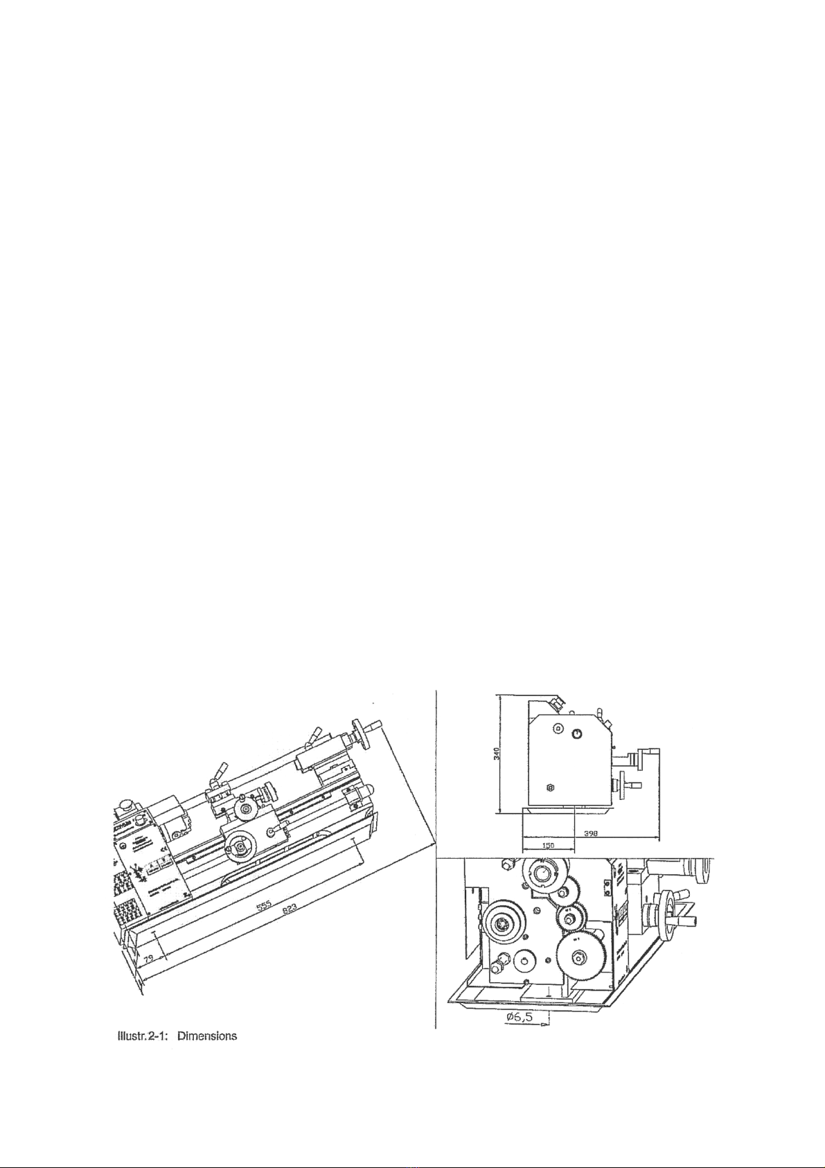
Take notice of the weight of the lathe when assembling. The weight amounts to 60kg.
Wear safety shoes
• Fasten the load suspension gear around the lathe bed
• Clamp the tailstock firmly before transporting the lathe
• Make sure that no add-on pieces or varnished parts are endangered due to the load suspension
2.2.3 Fixing
• Control the foundation of the lathe using a spirit level for horizontal orientation
• Make sure that the means of transport and the foundation on which the lathe is being placed can withstand
the load
• Place the lathe onto the provided foundation
• Screw the machine > Fix the lathe with the provided bore holes (2 pieces) together with the chip pan and the
provided foundation

Insufficient rigidity of the foundation leads to the superposition of vibrations between the lathe and foundation (natural
frequency of components). Insufficient rigidity of the entire lathe assembly also rapidly causes the lathe to reach
critical speeds, with unpleasant vibrations, leading to bad turning results.
2.3 First use
2.3.1 Cleaning and greasing
Cleaning the machine
Remove the anticorrosive agent applied to the lathe for transport and storage purposes. We recommend the use of
stove distillate.
Do not use any solvents, thinners, or other cleaning agents which could corrode the varnish on the lathe. Follow the
specifications and indications of the manufacturer of the cleaning agent.
Lubricate all bright machine parts with non-corrosive lubricating oil.
Grease the lathe using the lubrication chart (under “Inspection and maintainance”).
Control the function of movable and fixed parts
Check smooth running of all spindles.
Ensure the fastening screws of the lathe chuck are firmly tightened.
Clamp a workpiece into the lathe chuck, or bring the clamping jaws of the lathe chuck completely together before the
switch the lathe on.
Make sure that the current supply is working correctly
Connect the electrical supply cable (safety plug with earthing).
Warning!
Do not stand directly in front of the lathe chuck when you turn the machine on for the first time.

2.3.2 Optional accessories
4 jaw chuck 100mm
Flange for 4-jaw chuck
Face plate
Follow rest
Steady rest
Set of collet chucks, 1-16mm, 15 pieces (ER25)
ER25 Toolholder
Quick change tool holder AA
Single toolholder WAAD
Set of lathe tools, 10mm, 7 pieces
Set of tipped tools, 8mm, 11 pieces

3 Operation
3.1 Safety
Use the lathe only under the following conditions:
• The machine is in proper working order
• The lathe is used as prescribed
• The operating manual is followed
All abnormalities should be eliminated immediately. Stop the lathe immediately in the event of any abnormality in
operation and make sure it cannot be started up accidentally or without authorization.
3.2 Control and indicating elements
Warning!
Please be aware that the machine should only be run at low revs and high loads for a limited amount of time, then run
and unloaded at full speed to allow the motor to cool.

3.3 Clamping the tool
Clamp the turning tool into the tool holder.
The tool must be clamped firmly and with the least possible overhang in order
to absorb well and make sure that the cutting force is reliably generated during
the chip formation.
The maximum height between the supporting surface of the quadruplicate
toolholder and the center of the lathe chuck amounts to 10mm (11mm from
year of manufacture).
Adjust the height of the tool. Use the tailstock with the center point in order to
determine its required height.
If necessary, put the steel washers beneath the tool to achieve the required
height.
The blade of the tool must be exactly adjusted to the height of centers in order
to produce a shoulder-free front face. By facing, plain faces are being
produced which are rectangular to the axis of rotation of the workpiece. Here it
is distinguished between cross-facing, cross-slicing, and longitudinal facing.
3.4 Clamping a workpiece into the lathe chuck
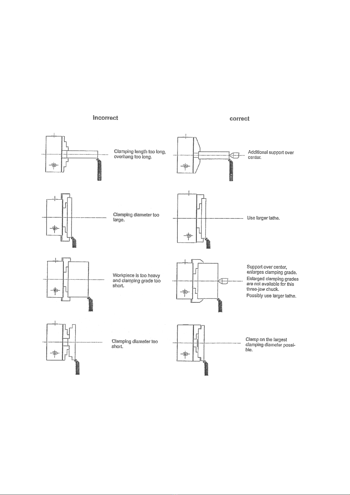
When the workpiece is being improperly clamped, there is a risk of injury as the workpiece may fly off or the jaws may
break. The following examples do not show all possible risks of danger.
The workpiece should be clamped safely and tightly on the lathe before starting operation. The clamping force should
be dimensioned in a way that ensures the workpiece is securely driven and that there are no dangers or deformations
in the workpiece.
Do not clamp any workpieces that exceed the permitted chucking capacity of the lathe chuck. The clamping force is
too low if its capacity is exceeded, the jaws may also come loose.
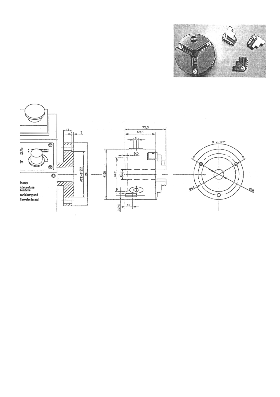
3.4.1 Replacing the clamp jaws on the lathe chuck
The clamping jaws and the three-jaw chuck are equipped with numbers.
Insert the clamping jaws at the correct position and in the right order into
the three-jaw chuck.
After replacement, bring the jaws completely together in order to ensure
that they are inserted correctly.
3.4.2 Head spindle seat
Optional accessory for this machine.
When disassembling the work support, it may fall on the engine bed and damage the guide rails. Place a wooden
plank or another adequate part on the engine bed in order to avoid damage.
• Disconnect the machine from the electrical supply
• Block the revolutions of the spindle. For instance, by inserting the square seat of the lathe chuck. Also ensure
that the engine bed is not damaged by the arm of the lever
• Loosen the three nuts on the flange of the lathe chuck to disassemble the work support
• Remove the work support to the front
• If required, loosen the work support by knocking it slightly with a plastic tip or rubber mallet
3.5 Switching on / off
Check that the engaging lever is not activating when cutting threads.
By switching the lathe on with high-speed setting and activating engaging lever, the lathe slide will move with high
speed.
Before switching the lathe on, turn the potentiometer for speed setting to a low-speed setting.
The electronics may be damaged if the machine is switched on at a full speed setting.
The machine can be switched on with the ON / OFF switch. The lathe may only be switched on when the change-over
switch is in the position of R or L.

3.6 Change-over switch
The sense of rotation of the lathe is performed by the change-over switch.
• The R marking means right-handed rotation. The lathe chuck turns anti-clockwise
• The L marking means left-handed rotation. In the left-handed rotation for instance, the lathe slide is being
reversed for thread cutting. In the position 0 the engine is switched on.
Wait until the lathe has come to complete halt before inverting the turning direction using the control levers. Changing
the turning direction during operation may cause damage to components.
3.6 Adjusting the speed
Adjust the speed with the potentiometer.
In order to use another speed range, you must change the position of the
synchronous belt on the pulleys.
Unplug the shockproof cover of the lathe before opening the protective
cover of the headstock.
3.6.1 Changing the speed range
• Unplug the shockproof cover from the mains
• Detach the protective cover of the headstock
• Loosen the fastening nut of the shim with a 14mm fork wrench
• Screw in the hexagon socket screw, reducing the tension of the
synchronous belt
• Lift the upper synchronous belt onto the required wheel diameter
• Proceed the other way around to tighten the synchronous belt. The correct
tension of the belt has been reached when you can still bend it
approximately 3mm with your index finger
Make sure the tension of the synchronous belt is correct. Excessive or insufficient
tension may cause damage.
3.7 Turning short tapers with the top slide
To turn short tapers the top slide is to be adjusted according to the required angle.
• Loosen the fastening screws
• Swivel the top slide
• Clamp the top slide again
• Clamp the top slide
3.8 Turning between centers
For the operation between centers check the clamping of the tailstock or
spindle sleeve.
Screw the safety screw at the end of the lathe bed in order to avoid
unintentional pulling of the tailstock out of the lathe bed.
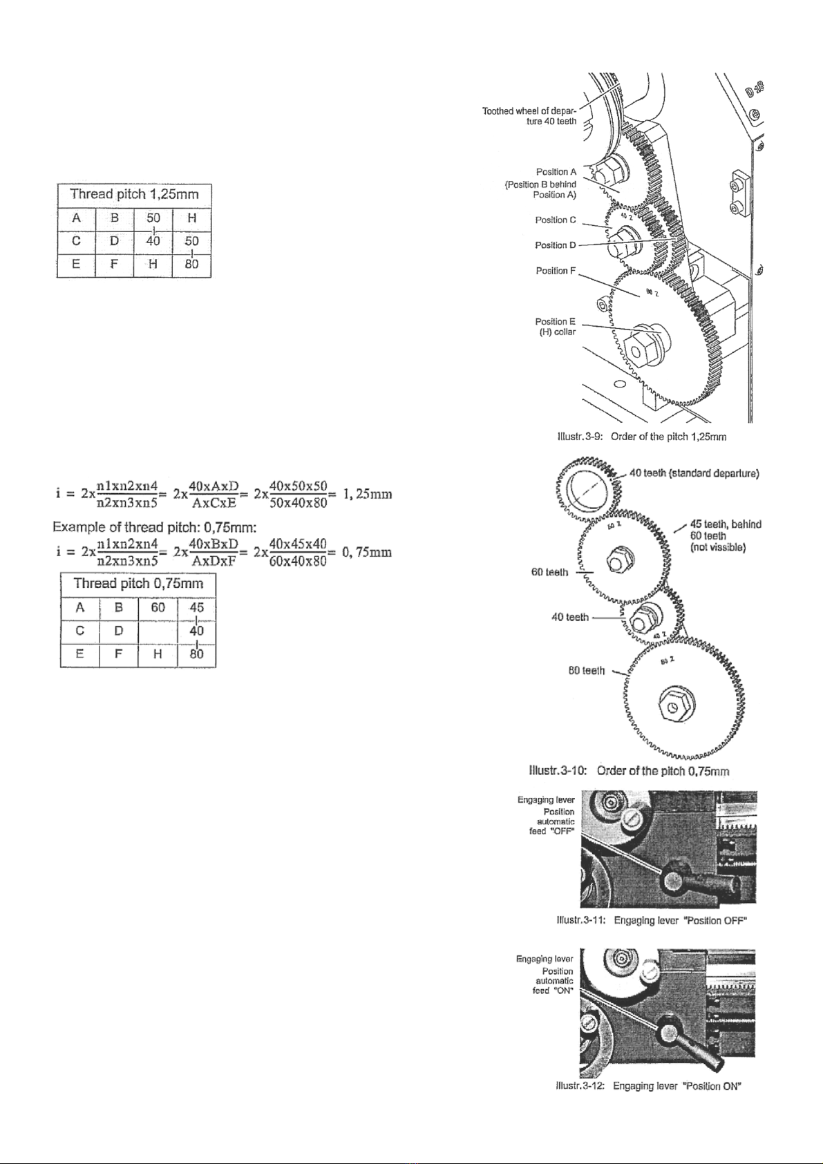
3.9 Adjusting feeds and thread pitches
In order to achieve a change of feed of a certain thread pitch, the
changes wheels are to be changed according to the table. You will
find the complete table on the lathe.
For example:
• The toothed wheel of departure with 40 teeth cams in the
toothed wheel A
• The toothed wheel A cams in the toothed wheel C
• The toothed wheel D cams in the toothed wheel F
• H means the vacuity (collar). You may as well use a smaller
toothed wheel which does not cam in with any other
toothed wheel
Example of transmission ratio:
The thread pitch of the leading spindle amounts to 2mm.
The toothed wheel of departure with 40 teeth cams in the toothed wheel A
The toothed wheel B cams in the toothed wheel D
The toothed wheel D cams in the toothed wheel F
Metrical threads are indicated as thread pitch. In the example above, the
lathe saddle moves by 1.25mm during one turn of the lathe chuck. Inch
threads are indicated as number of threads on the length of one inch. The
length of one inch amounts to 25.4mm.
3.9.1 Switching on the feed
When switching on the lathe with high revolution setting and the engaging
lever activated, the lathe saddle moves at a high speed.
If you switch on the lathe for instance at full speed of 2500min with the
order of the toothed wheels for thread pitch 1.25mm, the lathe saddle will
travel a distance of 52mm within one second.
Threads are always cut with the least possible speed.

3.10 General working notes
3.10.1 Coolant
Friction during the cutting processes causes high temperature at the cutting edge of the tool.
The tool should therefore be cooled during the cutting process. Cooling the tool with a suitable cooling lubricant
ensures better working results and a longer edge life of the cutting tool.
Use a water soluble and non-pollutant emulsion as a cooling agent. This can be acquired from authorized distributors.
Make sure that the cooling agent is properly retrieved. Respect the environment when disposing of any lubricants and
cooling agents. Follow the manufacturers disposal instructions.

4 Maintenance
In this section you will find important information about
• Inspection
• Maintenance
• Repair
Properly performed regular maintenance is an essential prerequisite for
• Safe operation
• Faulty-free operation
• Long service life of the lathe and
• The quality of the products you manufacture
Installations and equipment from other manufacturers must be in optimum condition.
4.1 Safety
The consequences of incorrect maintenance and repair work may include
• Very serious injury to users working on the lathe
• Damage to the lathe
Only qualified users should carry out maintenance and repair work on the lathe.
4.2 Inspection and maintenance
The type and extent of wear depends to a large extent on individual usage and service conditions. For this reason, all
intervals are only valid for the authorized conditions.
Interval
Where?
What?
How?
Every
Week
Machine Bed
Lubricate
Lubricate all blank steel parts with a non-corrosive oil
Headstock
Inspection
Control the tension of the synchronous belts
Lubricate
Slightly lubricate the change wheels and the leading
spindle with a lithium grease.
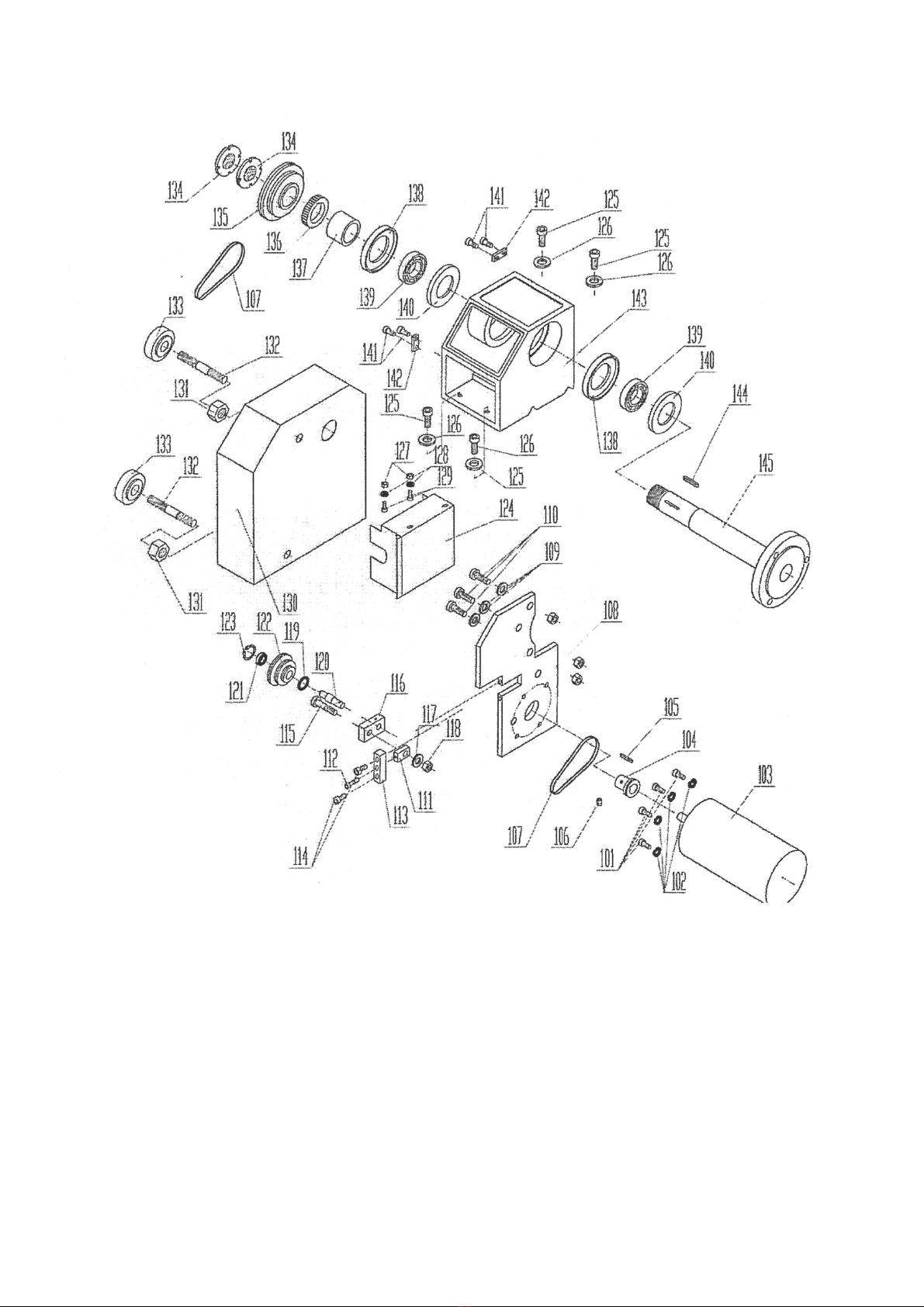
4.3 Spare parts drawing. Drive

4.4 Spare parts drawing. Top slide and compound slide

4.5 Spare parts drawing. Lathe slide
4.6 Spare parts drawing. Engine bed
Table of contents
Other CHESTER Lathe manuals

CHESTER
CHESTER Cobra Mill User manual

CHESTER
CHESTER Coventry Pro User manual

CHESTER
CHESTER Crusader User manual

CHESTER
CHESTER Craftsman User manual

CHESTER
CHESTER CONQUEST SUPER User manual

CHESTER
CHESTER DB8VS User manual

CHESTER
CHESTER Centurion Series User manual

CHESTER
CHESTER DB8VS User manual

CHESTER
CHESTER Voyager Lathe User manual

CHESTER
CHESTER 920 User manual


Popular Lathe manuals by other brands


Grizzly
Grizzly G0776 owner's manual

Jet
Jet CL-1640ZX operating instructions

Far Tools
Far Tools ML 400B Original translation

Carbatec
Carbatec WL-B1220H instruction manual

Carbatec
Carbatec WL-B1420P instruction manual

woodmizer
woodmizer Sawmill LT20 AC MH Series Safety, Setup, Operation & Maintenance Manual


