Chino IR-H Series User manual

INE-377-0P6CE Ver. 2.0
IR-H Series
HAND-HELD RADIATION
THERMOMETER
(Model: IR-HI, IR-HS, IR-HQH)
Always keep this instruction manual with the thermometer.
Please be sure to deliver this instruction manual to a person who
uses the thermometer.

INE-377-0P6CE Ver.. 2.0
-C1-
Request and notices
Please read this instruction manual for using the thermometer correctly and safely.
◆Request to the operator of the thermometer
This instruction manual describes the maintenance of the thermometer, too.
Keep this instruction manual with the thermometer.
If you have unclear points or need technical assistance, please contact your sales agent
of CHINO Corporation.
Notices
1. The information in this manual is subject to change without notice and does not represent
a commitment on the part of CHINO Corporation.
2. No part of this manual may be reproduced or transmitted in any form or by any means,
electronic or mechanical, including photocopying and recording, for any purpose other than the
purchaser's personal use without permission of CHINO Corporation.
3. CHINO Corporation shall not be liable for any operation results.
Software Ver. 2.0

INE-377-0P6CE Ver.. 2.0
-C2-
Preface
To use the thermometer correctly and safely, please keep the following safety measures
for the operation and storage of the thermometer.
This instruction manual is for the thermometer with the software version 1.40.
The software version of your thermometer is indicated in the label on the front side.
(Ref to [3.1.1 Front and both-side panels]).
1. Working conditions and environment
Make sure to press any keys until you hear an audible beep.
∙The thermometer is designed as a handheld type. Use a tripod or a simple type universal head for
long term or fixed mounting measurement.
∙The working temperature range of the thermometer is 0 to 50 °C. (No dew condensation)
∙Do not use the thermometer in dusty places, etc. Remove the dust after using it.
(For the cleaning of cover glass, refer to [8.3 Cleaning of cover glass] and, for the cleaning of
external display and eyepiece cover, refer to [8.4 Cleaning of external display and eyepiece
cover].)
∙Be careful not to give vibration or impact to the thermometer.
∙For preventing the consumption of the batteries, take off batteries when the thermometer is not
used.
2. Storage
∙Do not store the thermometer in hot and humid places. Make sure to store the thermometer with
the lens cap. Recommend to store the thermometer in room temperature with a dry pill.
∙Do not leave the thermometer in a car or its trunk room since the inside temperature will be
extremely high in summer. The thermometer may have troubles.
∙When the thermometer is not used for 2 weeks or more, take out the batteries from it. Otherwise,
the thermometer may be damaged by liquid leakage of the batteries.
∙When the thermometer has any trouble, please contact to your sales agent of CHINO Corporation.
3. Symbols in this instruction manual
The symbols shown below are used depending on important degrees for using the thermometer
safely and avoiding unexpected situations.
Important
degree Symbols Contents
1This symbol is attached to a title for the sentence with .
2For avoiding dangerous accidents (may cause death or serious injury)
like as electrical shock, fires, or troubles/damages of the thermometer.
3For avoiding injury or in physical damage to the thermometer.
4Information that we suggest to read carefully.
5Information that you can use as a reference.
Remarks
Reference
Caution
!
!
W
arning
W
arning
Software Ver. 2.0

INE-377-0P6CE Ver.. 2.0
-C3-
Warnings and Cautions
◆Please use the thermometer correctly by keeping the following items.
In addition, please read this instruction manual carefully and keep it at the place where you
can access easily.
The mark indicates prohibited operations.
Warning (May cause death or serious injury)
Make sure not see the sun through the viewfinder of the thermometer.
It may cause becoming blind.
Never directly face the objective lens to the sun to protect the detecting element.
For the measurement of high temperature objects, refer to the clause of "5.3 Cautions
on measurement".
Never operate the thermometer in places where combustible or volatile gas is existed.
It is extremely dangerous to use the thermometer in such environment.
Never put the batteries into fire, or never charge, short-circuit, heat or disassembly
the batteries.
Breaking or heating of the batteries may cause fire or injury.
For the AC adapter (IR-VHR), make sure to use 100 to 240VAC. Other voltage may
cause electrical shock, fire or trouble.
Never touch the AC adapter or receptacles by wet hands.
Never wet the AC adapter for avoiding fire.
Wipe the dust on the AC adapter for avoiding fire.
Never use the thermometer if it has been broken, smoking or nasty smelling.
These may cause fire. When the thermometer is broken, smoking, or nasty smelling,
turn the power supply switch off at once and take out the batteries, and contact to a sales
agent of CHINO Corporation.
Caution(May cause injury or physical damage)
Do not use other batteries than the batteries specified.
Load the batteries so that their polarities meet the polarity marks on the battery case.
Different polarities may cause fire, injury or damage by burst or liquid leakage of the
batteries.
Do not walk while sighting through the viewfinder of the thermometer.
It may cause accidents like as falling down.
Never take the thermometer apart or convert it.
These may cause trouble and danger.
Read the entire contents in this instruction manual to have the thermometer function
perfectly.
Dispose the batteries used to places specified with the disposal procedure specified.
!
!
!
!
!
!
!
!
!
!
!
!
!
Software Ver. 2.0

INST No.INE-377-0P6CE Ver. 2.0
-C 4-
CONTENTS
1. INTRODUCTION ............................................................................................................................1
1.1 GENERAL....................................................................................................................................1
1.2 CONFIGURATION ........................................................................................................................1
2. MODELAND ACCESSORIES.......................................................................................................1
2.1 MODEL .......................................................................................................................................1
2.2 ACCESSORIES .............................................................................................................................1
3. NAMES AND FUNCTIONS OF COMPONENT PARTS.............................................................2
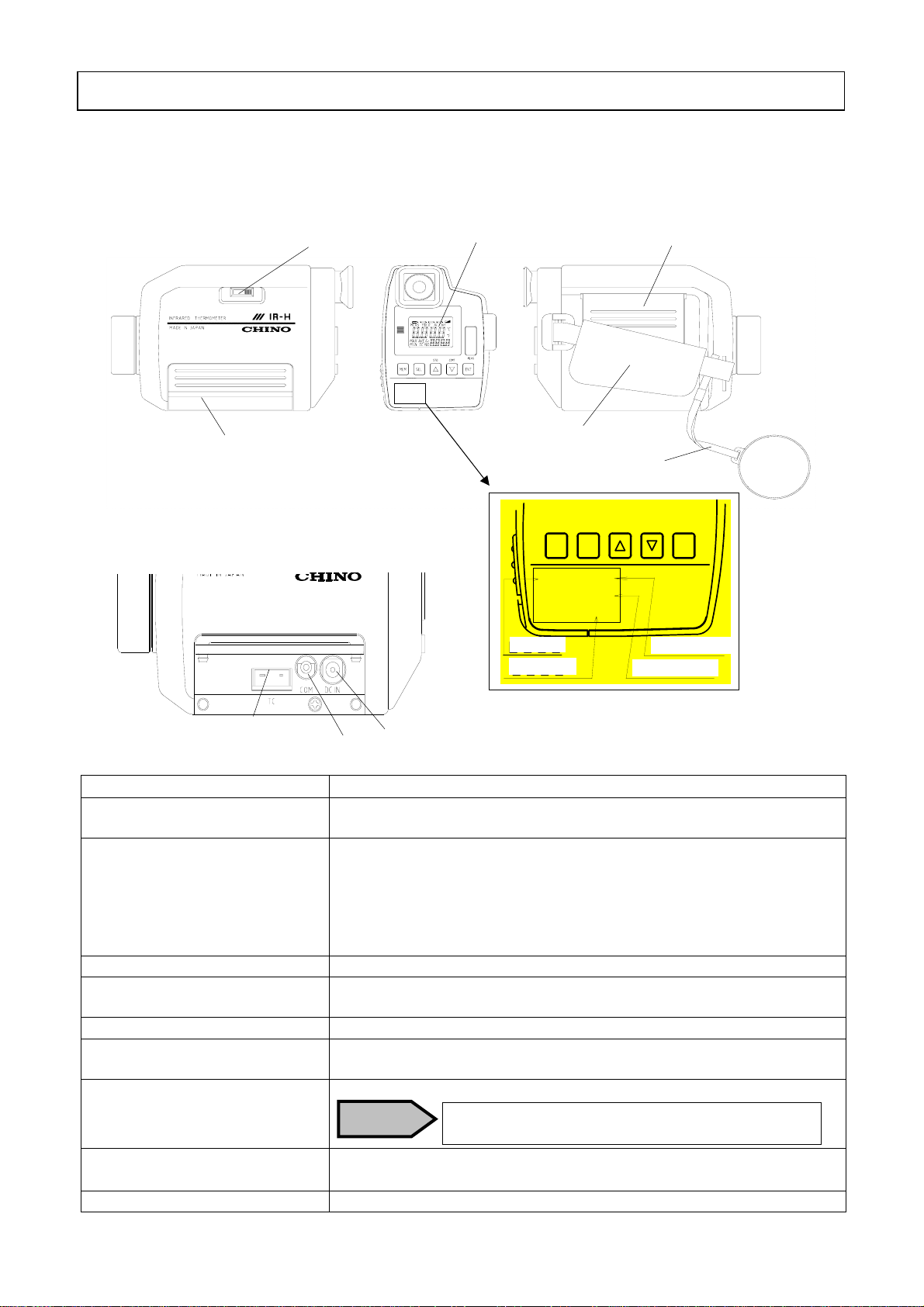
3.1 VIEWS.........................................................................................................................................2
3.1.1 Front and both-side panels...........................................................................................2
3.1.2 Connector cover inside..................................................................................................2
3.1.3 Functions........................................................................................................................2
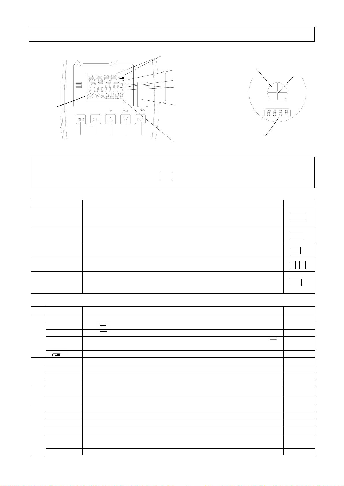
3.1.4 External display.............................................................................................................3
3.1.5 Viewfinder ......................................................................................................................3
3.1.6 Functions of keys ...........................................................................................................3
3.1.7 Markers..........................................................................................................................3
4. PREPARATION FOR MEASUREMENT .....................................................................................4
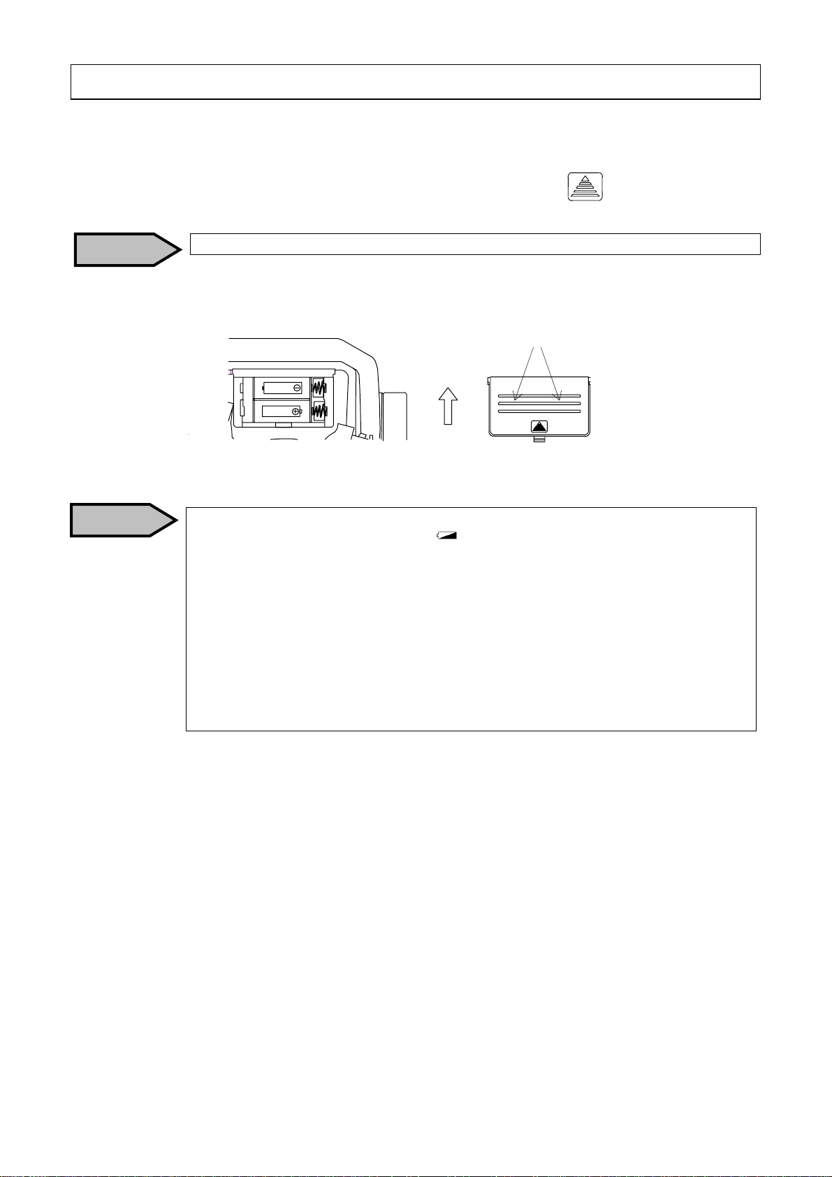
4.1 LOADING BATTERIES..................................................................................................................4
4.2 DISTANCE AND DIAMETER..........................................................................................................4
5. MEASURING....................................................................................................................................6
5.1 STANDARD MEASUREMENT MODE..............................................................................................6
5.2 CONTINUOUS MEASUREMENT MODE .........................................................................................7
5.2.1 Start of continuous measurement.................................................................................7
5.2.2 Cancellation of continuous measurement....................................................................7
5.3 CAUTION ON MEASUREMENT .............................................................................................8
5.4 EMISSIVITY PROGRAMMING ......................................................................................................8
5.5 EMISSIVITY PROGRAMMING BY THERMOCOUPLE.....................................................................9
5.6 PARAMETERS SELECTION.........................................................................................................10
5.6.1 Signal modulation mode selection.............................................................................. 11
5.6.2 Memory mode selection............................................................................................... 11
5.6.3 Communications mode selection ................................................................................12
5.6.4 Temperature unit selection..........................................................................................12
5.6.5 Thermocouple measurement selection.......................................................................13
5.6.6 2-color type/single color wide range type selection...................................................13
5.7 PARAMETERS PROGRAMMING .................................................................................................14
5.7.1 Low alarm setpoint programming.............................................................................14
5.7.2 High alarm setpoint programming............................................................................15
5.7.3 Modulation ratio selection..........................................................................................15
5.7.3 1) Modulation time constant selection (for dLEy selected)......................................16
5.7.3 2) Damping degree selection (for PEAk selected).....................................................16
5.7.4 Interval time programming for automatic data storage..........................................16
6. TEMPERATURE DATA STORAGE............................................................................................17
6.1 MANUAL DATA STORAGE MODE................................................................................................17
6.2AUTOMATIC DATA STORAGE MODE ..........................................................................................19
Software Ver. 2.0
!

INST No.INE-377-0P6CE Ver. 2.0
-C 5-
CONTENTS
6.3 DATA STORAGE NUMBER PROGRAMMINGAND REPLAY OF STORED DATA...............................22
6.3.1 Data storage number programming (Manual data storage mode) .......................22
6.3.2 Data storage number programming (Automatic data storage mode) ..................23
6.3.3 Recalling of stored data (Manual data storage mode) ...........................................24
6.3.4 Recalling of stored data (Automatic data storage mode) .......................................26
6.4 MEMORY FULL .......................................................................................................................28
6.5 ERASING ALL STORED DATA .....................................................................................................29
7. USER CALIBRATION ................................................................................................................30
7.1 USER CALIBRATION ................................................................................................................30
8. MAINTENANCE AND CHECK .................................................................................................33
8.1 SELF-DIAGNOSTIC FUNCTION ..................................................................................................33
8.2 STORAGE ..................................................................................................................................33
8.3 CLEANING OF OBJECTIVE LENS................................................................................................33
8.4 CLEANING OF EXTERNAL DISPLAY AND EYEPIECE COVER.......................................................33
9. ACCESSORIES ..............................................................................................................................34
9.1THERMOCOUPLE ......................................................................................................................34
9.2ACADAPTER (MODEL IR-VHRA) .................................................................................34
9.3TRIPOD (MODEL IR-ZBMT)AND UNIVERSAL HEAD (MODELIR-VMS) ..............................34
9.4 DATA LOGGING SOFTWARE ....................................................................................................34
10. LIST OF STARTING UP MODES..............................................................................................35
10.1 MODES AT START UP ...............................................................................................................35
10.2TABLE OF SCREENS.................................................................................................................35
10.3 MEASURING PARAMETER PROGRAMMING/DISPLAY..............................................................35
10.3.1 Emissivity programming/display .............................................................................35
10.3.2 Data storage number programming/dispay............................................................36
10.4 SYSTEM SETTINGS..................................................................................................................36
11. GENERAL SPECIFICATIONS ..................................................................................................37
11.1 SPECIFICATIONS .....................................................................................................................37
11.2 OUTSIDE DIMENSIONS ............................................................................................................37
12. EMISSIVITY TABLE ..................................................................................................................38
12.1 EMISSIVITY TABLE..................................................................................................................38
12.1.1 Emissivity table (λ= 0.65µm) ..........................................................................................38
12.1.2 Emissivity table (λ= 0.9µm) ............................................................................................39
12.1.3 Emissivity table (λ= 1.55µm) ..........................................................................................39
Note: Make sure to read the items with the mark of
Thearticlesof areincluded.
Software Ver. 2.0
!
Warning
!

INST No.INE-377-0P6CE Ver. 2.0
- 1 -
1.1 General
The IR-H series is small and lightweight handheld radiation thermometers with a clear viewfinder.
The direct viewfinder enables to measure small objects with distance. With the digital display in the
viewfinder, you can see a measured value while sighting to an object.
Three kinds of models are available, Model IR-HQH with both functions of [2-color type + Single
color wide range type] as a single unit, Single color type Model IR-HI for medium temperature, and
Single color type IR-HS for high temperature.
You can process the stored data by using a data logging software (IR-VXG1E … separate purchase
required … Ref to [9.4 Data Logging Software IR-VXG1E]).
1.2 Configuration
2.1 Model
I R-H□
Thermometer types
I : Single color type for medium temperature (300 to 1000ºC)
S : Single color type for high temperature (600 to 2000ºC)
QH : High functional type (600 to 2000ºC for 2-color type, 400 to 3000ºC for
single color wide range type)
2.2 Accessories
Names Quantity Remarks Names Quantity Remarks
AA (UM-3) battery 2 Alkaline Inspection certificate 1
Instruction manual 1 This manual
1. Introduction
2. Model and accessories
Thermocouple C510-01K (*1)
Thermocouple for high temp. C510-02K (*1) Personal
com
p
uter
(
*2
)
RS-232C
connection cord
IR-VHC (*2)
Data logging software
IR-VXG1 (*2)
Tripod IR-ZBMT
(
*
3)
Universal head
IR-VMS
(
*4
)
AC power adapter
IR-VHRA (*5)
Ribbon t
yp
e TC
EN61326
Emission: Class B
Immunity: Table 1 - minimum immunity requirement
*1, *2, *3, *4, *5: Separate purchase is required.
*5 : For a thermometer with CE-marking, mount an attached ferrite core to a connection cord at a
nearest place to the thermometer.

INST No.INE-377-0P6CE Ver. 2.0
- 2 -
3.1 Views
3.1.1 Front and both-side panels
3.1.3 Functions
Names Functions
(1) Connector cover For the connectors of 7, 8 and 9 shown above.
Open the cover from down side for the connection to the connectors.
(2) Beam attenuation filter
selector knob For setting a beam attenuation filter to ON (beam attenuation side).
For protecting your eyes when an object with high temperature over
1500ºC is measured or when you feel glare, measure the object through
the bean attenuation filter by setting the beam attenuation filter selector
knob to the beam attenuation side.
(Ref: [5.3 Cautions on measurement])
(3) External display A measured value and parameters are displayed.
(4) Battery cover Remove it by lightly pushing both sides of the triangle mark and sliding
it to the arrow direction. (Ref: [4.1 Loading batteries])
(5) Lens cap For protecting the objective lens.
(6) Side band For supporting the thermometer.
Adjust the length of band for your hand.
(7) Thermocouple connector For connecting to a thermocouple. (Ref: [9.1 Thermocouple])
8:PC connecting jack For connecting the communications cable.
(Ref: [9.4 Data Logging Software])
9:DC power supply jack For connecting to the AC adapter. (Ref: [9.2 AC Adapter])
3. Names and functions of component parts
(9)
(8)
(7)
Cautio
Thermocouples except the models listed in
[9.1 Thermocouple] cannot be connected.]
3.1.2 Connector cover inside
(
1
)
(2)
(
3
)
(
4
)
(
6
)
(
5
)
[Left side view] [Front side view] [Right side view]
* Label
* Confirm the software version of your
thermometer is 2.0
MEM SEL
STD
ENT
CONT MEAS
IR-HS2.00
600*2000℃
IH02XS 010
モデル名 ソフトVe r
測定温度範囲
製造番号
Model
Serial No. Software Ver.
Temp. Range

INST No.INE-377-0P6CE Ver. 2.0
- 3 -
3.1.4 External display
(2) (3) (4) (5) (6)
*1:Main display: Displays the measured value in the measurement mode or a parameter in the parameter
selecting/programming mode.
*2:Sub display: Displays the data selected by SEL key in the measurement mode or a parameter item in
the parameter selecting/programming mode.
3.1.6 Functions of keys
Keys Functions Indications
(1) Measure
Switch
Turns on the power supply and starts/stops a measurement.
(The power supply will be automatically turned off if any key is not pressed for
30 seconds in the hold mode.) MEAS
(2) Memory
key Changes from the standard or continuous measurement mode to the data storage
mode, or vice versa. MEM
(3) Select key Selects a data to be displayed in the sub display in measurement mode or a
selecting/programming item in the parameter selection/programming mode. SEL
(4) Up key
Down key Selects a parameter item or changes the numerical figure at a digit in the
parameter selection/programming mode. △▽
(5) Entry key Stores the parameter selected/programmed in the parameter selection/
programming mode or the measured value in the manual data storage mode.
(This key is not used in the automatic data storage mode.) ENT
3.1.7 Markers
Markers Major functions Indications
Tb Not used "Tb"
CONT The " " mark under "CONT" will light in the continuous measurement mode. "CONT"
MEM The " " mark under the "MEM" will light in the data storage mode. “MEM”
PEAK When the PEAK is selected in the signal modulation mode selection, the " "
mark under the "PEAK" will light. "PEAK"
(7)Main
marker
Will blink for low batteries.
MEAS Will light in the measurement mode. "MEAS"
HOLD Will light in the hold mode. "HOLD"
AL Will light when the low alarm is activated. "AL"
(8)Status
marker
AH Will light when the high alarm is activated. "AH"
oC Will light when a temperature is displayed in Celsius. "oC"
(9)Uit
oF Will light when a temperature is displayed in Fahrenheit. "oF"
MAX Will light when the sub display shows a maximum temperature. "MAX"
MIN Will light when the sub display shows a minimum temperature. "MIN"
AVE Will light when the sub display shows an average temperature. "AVE"
TC Will light when the sub display shows a temperature measured by a thermocouple. "TC"
ε (εr) Will light when the sub display shows an emissivity (ratio).
Single color type is the emissivity (ε) and 2-color type is the emissivity ratio (εr). "ε"or"εr"
(10)Sub mareker
NO Will light when the sub display shows a data storage number. "NO"
3. Names and functions of component parts
*1 Main dis
p
la
y
*2 Sub display Internal display
Targeting mark
(7) Main marker
(8) Status marker
(10)
Sub
marker
3.1.5 Viewfinder
(9) Measurement unit
display
(1) Measure switch
Targeting mark
center circle

INST No.INE-377-0P6CE Ver. 2.0
- 4 -
4.1 Loading batteries
• Remove the battery cover. Remove it by lightly pushing both sides of mark and sliding it to
the arrow direction.
4. Preparation for measurement
• Load two batteries with proper polarities.
Caution
Remove the battery cover by
sliding it upward while pushing
both sides lightly.
SUM‑3 SIZE
1
.
5V
×
2
• Battery life
The battery warning maker " " will blink when the battery capacity
becomes lower. Replace the batteries (Alkaline AA or UM-3 batteries).
(Ref:[3.1.7 Markers])
When the marker disappears, replace the batteries (Alkaline AA or UM-3
batteries), too.
• Caution on removing the batteries
Make sure to remove the batteries from the [no-spring] side.
• Battery replacement
Make sure to load the batteries to the [spring] side first.
Replace 2 batteries together.
Caution

INST No.INE-377-0P6CE Ver. 2.0
- 5 -
4.2 Distance and diameter
The relation of measuring distance and measuring diameter is shown below.
4.3 Targeting
For the accurate temperature measurement, target at an object correctly
The following figures (1), (2), and (3) show the correct targeting based on the relation of the
measuring distance and the measuring diameter.
(1) For the measurement distance is shorter than 3m
Measurement diameter becomes “larger” than the targeting mark.
(2) For the measurement distance is about 3m.
The measurement diameter and the inner side of the targeting mark are almost “same”.
(3) For the measurement distance is longer than 3m
Measurement diameter becomes “smaller” than the targeting mark.
4. Preparation for measurement
• The measuring diameter is fixed to ø20mm for the measuring distance up
to 4m.
• For the measuring distance shorter than 3m, make sure to have the measuring
diameter larger than the targeting mark.
Remarks
φ
90
φ
33
φ
20
φ
20
10m 5m 4m 0m
( At 90% energy limit )
(1) For the measurement
distance is shorter than 3m (2) For the measurement
distance is about 3m (3) For the measurement
distance is longer than 3m

INST No.INE-377-0P6CE Ver. 2.0
- 6-
(Common to [5.1 Standard measurement mode] and [5.2 Continuous measurement mode])
Externaldisplay Main marker Internaldisplay
Statusmarker
Maindisplay
Submarker Subdisplay
* Data in the sub display (Common to [5.1 Standard measurement mode] and [5.2 Continuous
measurement mode])
Sub marker Data displayed in sub display
ε(εr) Emissivity (ε) for single color type, Emissivity ratio (εr) for 2-color type
TC
Temperature data measured by a thermocouple is displayed when you select on
(enable) in [5.6.5 Thermocouple measurement selection].
Refertothefollowing .
"oFF" is dis
p
la
y
ed when
y
ou select oFF
(
disable
)
.
MIN Minimum tem
p
erature durin
g
measurement
(
durin
g
the status marker "MEAS" li
g
hts
)
MAX Maximum temperature during measurement (during the status marker "MEAS" lights)
AVE Average temperature during measurement (during the status marker "MEAS" lights)
(Moving average of 25 points)
NO Stored data storage number. Lights in the data storage mode only.
5.1 Standard measurement mode
This mode is for measurement with holding the thermometer by hands.
• Sight through the viewfinder and match the center circle of the targeting circle to the center of
object measured.
• Press MEAS key for about 1 second to turn on the power supply and start a measurement. The
temperature measured will be displayed in the internal and external displays, and the status marker
“MEAS” will light in the external display.
(The measurement is continued during MEAS key is being pressed.)
• Select the data to be displayed in the sub display by pressing SEL key if necessary.
•By releasing MEAS key, the measurement will stop and the measured value will be held.
The status marker "MEAS" will disappear and "HOLD" will light.
5. Measuring *Make sure to press any keys until you hear an audible beep.
Tb CONT MEM PEAK
MEAS HOLD AL AH
C
F
MAX AVE εr
MIN TC NO
• The internal display will disappear in 10 seconds in the hold mode and
the power supply will be automatically turned off if any key is not pressed
for 30 seconds in the hold mode.
Remarks
• In [5.6.5 Thermocouple measurement selection], when you select on (enable)
and display "TC" in the sub marker by SEL key, "oFL" will be displayed in the
sub display if the temperature data measured by the thermocouple is higher than
1220ºC (or 2228ºF). If the temperature is lower than -50ºC (or -58ºF), "uFL"
will be displayed.
• On the condition mentioned above, if the thermocouple is disconnected, "uFL"
will be displayed in the sub display.
Remarks
• "oFL" will be displayed in the main and sub displays if the temperature data
measured is higher than [the measuring range + 20ºC (or +36ºF)] or "uFL" will
be displayed if it is lower than [the measuring range - 20ºC (or -36ºF)].
Remarks
Remarks

INST No.INE-377-0P6CE Ver. 2.0
- 7-
5.2 Continuous measurement mode
5.2.1 Start of continuous measurement
This mode is for continuous measurement by fixing the thermometer on a tripod or a universal head.
• Sight through the viewfinder and match the center circle of the targeting circle to the center
of object measured
• For the continuous measurement mode, press MEAS key while pressing ▽key. As soon as all
segments of the external display (Ref. 3.1.4 [External display]) light, release MEAS key.
The " " mark under the main marker "CONT" and the status marker "HOLD" will light.
・
・Press MEAS key to start the continuous measurement. The status marker "HOLD" will disappear
and the status marker "MEAS" will light.
• Press MEAS key again to hold the measured value. The status marker "HOLD" will light.
5.2.2 Cancellation of continuous measurement
• For canceling the continuous measurement mode, press MEAS key for about 1 second while
pressing △key on the condition that the power supply is off. Confirm that the " " mark under
the main marker "CONT" disappeared.
5. Measuring *Make sure to press any keys until you hear an audible beep.
• The power supply will be automatically turned off if any key is not pressed for
30 seconds in the hold mode.
Remarks
Reference
• The continuous measurement shorts the battery life. We recommend to use the
AC adapter (Model: IR-VHRA … separate purchase required).
• The status marker "MEAS" will light depending on its releasing timing of
MEAS key. In this case, press MEAS key only again to light the status marker
"HOLD".
Caution
Remarks • The internal display will disappear in 10 seconds after the measurement starts.
• In [5.6.5 Thermocouple measurement selection], when you select on (enable)
and display "TC" in the sub marker by SEL key, "oFL" will be displayed in the
sub display if the temperature data measured by the thermocouple is higher than
1220ºC (or 2228ºF). If the temperature is lower than -50ºC (or -58ºF), "uFL"
will be displayed.
• On the condition mentioned above, if the thermocouple is disconnected, "oFL"
will be displayed in the sub display.
Remarks
• "oFL" will be displayed in the main and sub displays if the temperature data
measured is higher than [the measuring range + 20ºC (or +36ºF)] or "uFL" will
be displayed if it is lower than [the measuring range - 20ºC (or -36ºF)].
Remarks

INST No.INE-377-0P6CE Ver. 2.0
- 8-
5.3 Cautions on measurement
Warning
5.4 Emissivity programming
If the emissivity of object measured is low, the temperature displayed becomes lower than the exact
temperature and the emissivity is to be compensated.
• Press MEAS key for about 1 second to turn on the power supply and then release MEAS key.
The status marker "HOLD" will light.
• In the hold mode, press SEL key several times to enter the emissivity programming mode "ε"
("εr" for 2-color type) in the sub marker. (Ref: [3.1.7 Markers]).
• By pressing either △or ▽key, the least
significant digit of 4-digit numeric will blink for
programming it.
• Program the desired figure by pressing △or
▽key.
• Press ENT key. The blinking will stop and the
programming digit will shift to the next higher digit.
• Repeat the above procedure up to the most significant digit for programming the emissivity
(4 digits).
• By pressing ENT key at the most significant digit, the programming of emissivity will be
completed.
5. Measuring *Make sure to press any keys until you hear an audible beep.
!
• Light path
Be careful not to introduce water drops, dust particles, smoke, steam, or other
foreign substances into the light path between the object measured and the
objective lens of the thermometer.
• Interference causing high indication
Be careful not to apply the direct sunlight, light of an incandescent lamp, flame
or other thermal radiation to the object measured and the objective lens of the
thermometer.
Caution
• Never directly sight the objective lens of the thermometer to the sunlight for
protecting your eyes and a detecting element.
Warning
Warning • For the measurement of object exceeding 1500oC, make sure to set the beam
attenuation filter selector knob to "ON" (beam attenuation side) for protecting
your eyes. (Refer to the above figure.)
• However, when you feel glare on the measurement of objects lower than
1500oC, set the beam attenuation filter selector knob to "ON" (beam attenuation
side). (Refer to the above figure.)
Tb CONT MEM PEAK
MEAS HOLD AL AH
C
F
MAX AVE εr
MIN TC NO
Status
marker
Sub
marker
Main
marker
Sub
display
Main
dis
p
la
y
ON
FILTER
Beam attenuation side
Remarks • The programming range is 1.900 to 0.100. (0.001 increment)
• The default is "1.000".

INST No.INE-377-0P6CE Ver. 2.0
- 9-
5.4 Emissivity programming
5.5 Emissivity programming by thermocouple
The thermometer can be used as a surface thermometer by connecting a K type thermocouple.
Further the emissivity of the thermometer can be automatically programmed by assuming that the
surface temperature measured by the thermocouple is a true temperature
• Press MEAS key for about 1 second to turn on the power supply and then release to MEAS key.
The status marker "HOLD" will light.
• Press SEL key to display "TC"(thermocouple input mode) in the sub marker.
(Ref: [3.1.7 Markers]).
• Press MEAS key to take a measurement by the thermometer and a thermocouple simultaneously.
• After the measurement, the emissivity will be automatically programmed by pressing ENT key
in the hold mode.
5. Measuring *Make sure to press any keys until you hear an audible beep.
• The emissivity programming is disabled in the data storage mode (when the
"" mark under the main marker "MEM" lights). For canceling the data
storage mode, press MEM key. The " " mark under the main marker
"MEM" will disappear.
Caution
• In [5.6.5 Thermocouple measurement selection], when you select on (enable)
and the thermocouple is disconnected, "oFL" will be displayed in the sub
display.
Reference
• The default parameter of thermocouple input is oFF (thermocouple
measurement disabled.).
• For the programming it to on (thermocouple measurement enabled), refer to [5.6
Programming parameters] and [5.6.5 Thermocouple measurement selection].
Remarks
Caution • The emissivity programming is disabled in the data storage mode (when the
"" mark under the main marker "MEM" lights). For canceling the data
storage mode, press MEM key.
• If you know the emissivity of object measured, program to its value.
• If the emissivity is unknown, measure the temperature of object by
a thermocouple and program the emissivity to display the same temperature.
• The reference table of emissivity is shown in [12. Emissivity table]
Reference

INST No.INE-377-0P6CE Ver. 2.0
- 10 -
5.6 Parameters selection (This paragraph explains the items highlighted.)
The thermometer provides parameters for measurements as shown in the list below. By referring to
the list, select or program the parameters.
Parameter item Sub
display Parameter Default Paragraph
Low temperature alarm
programming
AL oFF, 300 to 1000ºC/572 to 1832ºF (IR-HI)
oFF, 600 to 2000ºC/1112 to 3632ºF (IR-HS)
oFF, 400 to 3000ºC/752 to 5432ºF (IR-HQH)
oFF 5.7.1
High temperature alarm
programming
AH oFF, 300 to 1000ºC/572 to 1832ºF (IR-HI)
oFF, 600 to 2000ºC/1112 to 3632ºF (IR-HS)
oFF, 400 to 3000ºC/752 to 5432ºF (IR-HQH)
oFF 5.7.2
Signal modulation
mode selection modu dELy, PEAk dELy 5.6.1
Modulation ratio selection tAu
dEc
0.0, 0.2, 0.5, 1.0 (second)
0, 2, 5, 10ºC (ºF)/second
0.0s
0ºC/s
5.7.3
Data storage mode
selection mmod mAn, int mAn 5.6.2
Data storage interval
programming int 1 to 7200 seconds 60s 5.7.4
All stored data erasing AdEL no, yES no 6.5
Communications mode
selection Com trnS, Com trnS 5.6.3
Measuring unit selection Unit C, F C 5.6.4
Thermocouple
enable/disable selection TC oFF, on oFF 5.6.5
2-color/single color wide
selection *CoLr 2, 1 2 5.6.6
* The 2-color/single color wide selection is displayed in Model IR-HQH only.
• Press MEAS key for about 1 second to turn on the power supply and then release MEAS key.
The status marker "HOLD" will light.
• Press SEL key for about 2 seconds in the hold mode to move to the programming mode.
A parameter will be displayed in the main display and its item will be displayed in the sub display.
• Press SEL key for selecting a parameter item. (Ref: [10.4 System settings]
• For the selecting or programming procedure of the above parameters, refer from [5.6.1 Signal
modulation mode selection] to [5.6.6 2-color type /single color wide range type selection].
5. Measuring *Make sure to press any keys until you hear an audible beep.
• If SEL key is pressed for 2 seconds in the programming mode or if any key is
not pressed for 1 minute, the thermometer will return to the measurement mode.
Remarks
Tb CONT MEM PEAK
MEAS HOLD AL AH
C
F
MAX AVE εr
MIN TC NO
Main display Display of [parameter]
Sub display Display of [its item]
«Programming mode screen »

INST No.INE-377-0P6CE Ver. 2.0
- 11 -
5.6.1 Signal modulation mode selection
Maximum value and average value can be extracted continuously from the measurement signal
(real signal).
• Press MEAS key for about 1 second to turn on the power supply and then release MEAS key.
The status marker "HOLD" will light.
• Press SEL key for about 2 seconds to in the hold mode to move to the programming mode.
A parameter will be displayed in the main display and its item will be displayed in the sub display.
• Press SEL key to display "modu" in the sub display.
• By pressing △or ▽key, either "dELy" (average value) or "PEAk" (maximum value) will
blink in the main display.
• Select your desired mode and press ENT key.
• By storing the dELy, the "dELy" will light in the
main display. By storing the PEAk, the "PEAk" will
light in the main display and the " " mark will
light under the main marker "PEAK".
DELy The temperature displayed is based on the first-order lag signal selected in
[5.7.3-1 Modulation ratio selection].
PEAk When the temperature measured increases, its displayed value is based on the real signal.
When the temperature measured decreases, its displayed value is based on the value
selected in [5.7.3-2 Damping degree selection].
5.6.2 Data storage mode selection
MAn Manual data storage mode: Stores the data each time ENT button is pressed.
Int Automatic data storage mode: Stores the data at the interval time programmed.
For storing the measured data, select the manual data storage mode or the automatic data storage
mode.
• Press MEAS key for about 1 second to turn on the power supply and then release MEAS key.
The status marker "HOLD" will light.
• Press SEL key for about 2 seconds in the hold mode to move to the programming mode.
A parameter will be displayed in the main display and its item will be displayed in the sub display.
• Press SEL key to display "mmod" in the sub display.
• By pressing △or ▽key, either "mAn" (manual
data storage mode) or "int" (automatic data storage
mode) will blink in the main display.
• Select your desired mode and press ENT key.
5. Measuring *Make sure to press any keys until you hear an audible beep.
・The default is "dELy".
Remarks
Reference
• This data storage selection is effective in the data storage mode.
(Ref. [6.1 Manual data storage mode] and [6.2 Automatic data storage mode])
• The default is "mAn" (manual data storage mode).
Remarks
Main display
Tb CONT MEM PEAK
MEAS HOLD AL AH
C
F
MAX AVE εr
MIN TC NO
Sub display
Main display
Sub display
Tb CONT MEM PEAK
MEAS HOLD AL AH
C
F
MAX AVE r
MIN TC NO

INST No.INE-377-0P6CE Ver. 2.0
- 12 -
5.6.3 Communications mode selection
Select one-way communications to or both-way communications with a personal computer.
• Press MEAS key for about 1 second to turn on the power supply and then release MEAS key.
The status marker "HOLD" will light.
• Press SEL key for 2 seconds in the hold mode to
move to the programming mode. A parameter will be
displayed in the main display and its item will be
displayed in the sub display.
• Press SEL key to display "Com" in the sub display.
• By pressing △or ▽key, either "trnS"
(one-way communications) or "Com" (both-way
communications) will blink in the main display.
• Select your desired mode and press ENT key.
TrnS
• This mode is used for monitoring, by a personal computer, of emissivity, temperature and
thermocouple temperature as the measured data.
• The transmission of data is one-way from the thermometer to the personal computer when
MEAS key is released in the standard measurement mode and at every 0.2 second in the
continuous measurement mode.
Com
• This mode is used to see the display and settings of parameters by a personal computer in
addition to the monitoring in "trnS" mode,
• This mode is both-way communications by sending a response from the thermometer
against the communications command from a personal computer
5.6.4 Temperature unit selection
Select ºC or ºF for measuring temperature unit.
• Press MEAS key for about 1 second to turn on the power supply and then release MEAS key.
The status marker "HOLD" will light.
• Press SEL key for about 2 seconds in the hold mode
to move to the programming mode. A parameter will
be displayed in the main display and its item will be
displayed in the sub display.
• Press SEL key to display "unit" in the sub display.
• By pressing △or ▽key, either "C" (ºC)
or "F" (ºF) will blink in the main display.
• Select your desired mode and press ENT key.
5. Measuring *Make sure to press any keys until you hear an audible beep.
• The default is "trnS" (one-way transmission from thermometer).
Remarks
Main display
Sub display
Tb CONT MEM PEAK
MEAS HOLD AL AH
C
F
MAX AVE εr
MIN TC NO
• The default is "C" (ºC).
Remarks
Tb CONT MEM PEAK
MEAS HOLD AL AH
C
F
MAX AVE εr
MIN TC NO
Main display
Sub display
Unit display

INST No.INE-377-0P6CE Ver. 2.0
- 13 -
5.6.5 Thermocouple measurement selection (Separate purchase of a K type T/C is required.)
Select to measure by a thermocouple. (Ref: [9.1 Thermocouple])
• Press MEAS key for about 1 second to turn on the power supply and then release MEAS key.
The status marker "HOLD" will light.
• Press SEL key for about 2 seconds in the hold mode to move to the programming mode.
A parameter will be displayed in the main display and its item will be displayed in the sub display.
• Press SEL key to display "tC" in the sub display.
• By pressing △or ▽key, either "oFF" (disable)
or "on" (enable) will blink in the main display.
• Select your desired mode and press ENT key.
5.6.6 2-color type/single color wide range type selection (* High functional type IR-HQH only)
Select a measurement mode by 2-color type or single color wide range type in Model IR-HQH.
• Press MEAS key for about 1 second to turn on the power supply and then release MEAS key.
The status marker "HOLD" will light.
• Press SEL key for about 2 seconds in the hold mode to move to the programming mode.
A parameter will be displayed in the main display and its item will be displayed in the sub display.
• Press SEL key to display "CoLr" in the sub display.
• By pressing △or ▽key, either "2" (2-color type)
or "1" (single color wide range type) will blink in the
main display. Select your desired mode and press
ENT key.
5. Measuring *Make sure to press any keys until you hear an audible beep.
• The default is "oFF" (disable).
Remarks
Tb CONT MEM PEAK
MEAS HOLD AL AH
C
F
MAX AVE εr
MIN TC NO
Main display
Sub display
• The default is "2" (2-color type).
Remarks
Tb CONT MEM PEAK
MEAS HOLD AL AH
C
F
MAX AVE εr
MIN TC NO
Main display
Sub display

INST No.INE-377-0P6CE Ver. 2.0
- 14 -
5.7 Parameters programming
The thermometer provides parameters for measurements as shown in the list below.
By referring to the list, program the parameters.
Parameter item Sub
display Parameter Defau
lt Paragra
ph
Low temperature alarm
programming AL oFF, 300 to 1000ºC/572 to 1832ºF(IR-HI)
oFF, 600 to 2000ºC/1112 to 3632ºF (IR-HS)
oFF, 400 to 3000ºC/752 to 5432ºF (IR-HQH)
oFF 5.7.1
High temperature alarm
programming AH oFF, 300 to 1000ºC/572 to 1832ºF(IR-HI)
oFF, 600 to 2000ºC/1112 to 3632ºF (IR-HS)
oFF, 400 to 3000ºC/752 to 5432ºF (IR-HQH)
oFF 5.7.2
Signal modulation mode
selection modu dELy, PEAk dELy 5.6.1
Modulation ratio selection
*tAu
dEc 0.0, 0.2, 0.5, 1.0 (second)
0, 2, 5, 10ºC (ºF)/second 0.0s
0ºC/s 5.7.3
Data storage mode selection mmod mAn, int mAn 5.6.2
Data storage interval
programming int 1 to 7200 seconds 60s 5.7.4
All stored data erasing AdEL no, yES no 6.5
Communications mode
selection Com trnS, Com trnS 5.6.3
Measuring unit selection Unit C, F C 5.6.4
Thermocouple
enable/disable selection TC oFF, on oFF 5.6.5
2-color/single color wide
selection CoLr 2, 1 2 5.6.6
* The modulation ratio selection differs by the selection of the signal modulation mode.
(Ref: [5.6.1 Signal modulation mode selection])
5.7.1 Low alarm setpoint programming
This programming is for a judgment of low alarm during measurement.
When the low alarm is judged, the status marker "AL" will light and the buzzer will sound. When the
"oFF" is selected, neither the alarm judgment can be executed nor the buzzer can be sound.
• Press MEAS key for about 1 second to turn on the power supply and then release MEAS key.
The status marker "HOLD" will light.
• Press SEL key for about 2 seconds in the hold mode to move to the programming mode.
A parameter will be displayed in the main display and its item will be displayed in the sub display.
• Press SEL key to display "AL" in the sub display.
• By pressing △key, the least significant digit will blink for programming it.
• Program the desired figure by △or ▽key and
press ENT key for shifting the programming digit to
the next higher digit.
• Repeat the above procedure up to the most significant
digit.
• By pressing ENT key at the most significant digit,
the programming of low alarm setpoint will be
completed.
5. Measuring *Make sure to press any keys until you hear an audible beep.
Tb CONT MEM PEAK
MEAS HOLD AL AH
C
F
MAX AVE εr
MIN TC NO
設定値
Main display
Sub display
• The programming range is “oFF” or the followings.
300 to 1000ºC/572 to 1832ºF (IR-HI), 600 to 2000ºC/1112 to 3632ºF (IR-HS)
400 to 3000ºC/752 to 5432ºF (IR-HQH)
• The default is "oFF".
Reference
This manual suits for next models
3
Table of contents
Other Chino Thermometer manuals

Chino
Chino IR-BAT Series User manual

Chino
Chino TP-S Easy Thermo User manual

Chino
Chino IR-AH Series User manual

Chino
Chino IR-CA series User manual

Chino
Chino IR-E Series User manual

Chino
Chino IR-CZ Series User manual

Chino
Chino IR-SA Series User manual

Chino
Chino IR-FA Series User manual

Chino
Chino IR-BZ Series User manual

Chino
Chino IR-CAK User manual