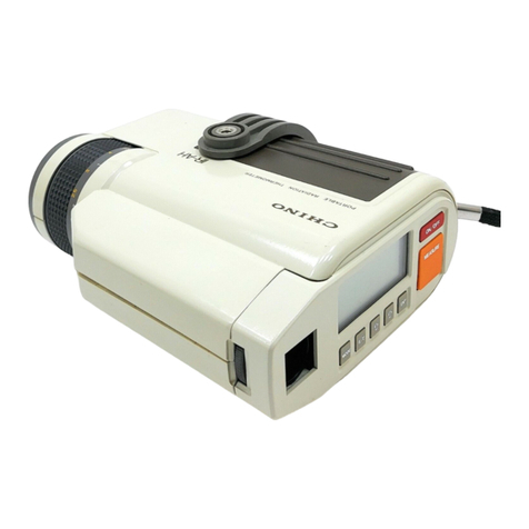
Chino IR-BAT Series User manual

INST No. INE-412-P7CE
IR-BAT series
COMPACT INFRARED
RADIATION THERMOMETER
Model:IR-BAT1A, IR-BAT1B, IR-BAT2A
IR-BATSA, IR-BATSB
IR-BAT1M, IR-BAT1P, IR-BAT2M
IR-BATSM, IR-BATSP
PREFACE/ Request and notices
Request to designers, instrument controllers, and sale agents
Make sure to deliver this instruction manual to the operator of this thermometer
Request to the operator of this instrument
This instruction manual is necessary for maintenance, too.
Keep this manual with due care until this thermometer is discarded.
NOTE
1.The descriptions of this manual are subject to change without
notice.
2.If a question has arisen or if an omission was found in this
manual, please contact your nearest CHINO’s sales agent.
3.We are not responsible for any results by operation of this
thermometer.
Thank you for your purchase of IR-BAT
series Compact
infrared radiation thermometer.
Please read this instruction manual for using this thermometer
correctly, safely and also preventing troubles in advance.
marking
EMC directive.
EN61326 -1 Class A

INST No. INE-412-P7CE
For the purpose of using this thermometer safely, observe the following cautions for safety
during the operation, maintenance, and repair of this thermometer.
Take safety measures separately against wrong operation, troubles, and other circumstances
of this thermometer if necessary.
This instruction manual uses the following symbol marks for safe.
CAUTIONS FOR SAFETY
Item Cautions
Power supply Make sure that the voltage of the power source meets the rated power supply of
this thermometer before operation.
Prohibition of use in a
gaseous atmosphere Never operate this thermometer at a place where a combustible gas, an
explosive gas or their vapors exist, otherwise a very dangerous accident
will occur. It is extremely dangerous to use this thermometer under such
environment
s
.
Never touch the interior To prevent from trouble, don't touch the inside of this thermometer by hand.
Caution on external
connections For connection to external equipment, make sure to turn off the power supply
and also read instruction manual for the equipments.
Prohibition disassembling
and modification Don't disassemble nor modify this thermometer. If you disassemble or
modify this thermometer, it will be dangerous to causing the trouble.
Cautions on maintenance
and check of the lens When wiping out the dirt of the lens, don't use organics solvents except an
alcohol, water and the detergents absolutely.
If used, it will cause the trouble.
Type Model
Measuring
ran
ge
Response
time (*)
Diameter/
Distance
Measuring
wavelength
General
General type IR-BAT1A 0 to 300 ºC 100ms Ø40/500mm
8to14m
IR-BAT1B 0 to 600 ºC
Small diameter, short distance
IR-BAT2A 0 to 300 ºC 100ms Ø5/80mm
Small diameter, long distance IR-BATSA 0 to 300 ºC 100ms Ø40/1000mm
IR-BATSB 0 to 600 ºC
Type Model
Measuring
range
Response
time (*)
Measuring
diameter
Measuring
wavelength
High speed
General type IR-BAT1M 0 to 300 ºC 50ms Ø40/500mm
8to14m
IR-BAT1P 0 to 600 ºC
Small diameter, short distance IR-BAT2M 0 to 300 ºC 50ms Ø5/80mm
Small diameter, long distance IR-BATSM 0 to 300 ºC 50ms Ø40/1000mm
IR-BATSP 0 to 600 ºC
Observe this caution item strictly for avoiding a danger, otherwise negligence of this
caution may cause an electric shock accident or other accidents resulting in
operator’s death or injuries.
Observe this caution item strictly, otherwise negligence of this caution may cause the
damage of this thermometer or measuring errors.
This mark is attached to each title covering instructions
This mark shows the act of the prohibition.
Warning
Caution
!
Warning
FOR SAFE USE
1.
Models
and main specifications (*Response time: 95
)

INST No. INE-412-P7CE
This infrared radiation thermometer measures temperature quickly without contact and can be used as a
FAsensor and a temperature switch. The converting functions are built-in.
Read the pertinent chapter well concerning use.
Conditions for CE conformance:
One (1) set of the thermometer should be used with the connection cable (up to 30m) connected to
one (1) set of DC power source unit, and all of these should be used in doors.
3.1 General type
3.2 Extension cable type: Figure of extension cable
2.
General
3
.
Each part name and outside dimensions
(6)
(7)
Control panel
15 85
f26
I N F R A R E D T H E R M O M E T E R I R- B
21
155
32
22
(2) (3)
(4)
(5)
(1)
25 113
(10)
(11)
(12)
4-M2 Screw for control panel cover
(8) 2-M4Depth 4
(9) 1/4w Depth 4
BA019T 004
IR-BAT1A
0*300℃/03
BA044T 004
IR-BAT1A
0*300℃/03 Temperature range/Software version
Model
Serial No.
Serial No. Label
CE mark
(1) V-shaped groove
(2) Lens
(3) Sight line
(4) 3mm O tip
(5) Cable
(6) Power supply
(7) Control panel cover
(8) M4 screw hole for L metal fittings for instaltion
(9) Screw hole for mounting the tripod
(10) Emissivity (e) setting digital switch (*1.0)
(11) Emissivity (e) setting digital switch (*0.1)
(12) Emissivity (e) setting digital switch (*0.01)
Unit: mm
Unit: mm
I N F R A R E D T H E R M O M E T E R I R- B
2000

INST No. INE-412-P7CE
4.1 Cautions on installation
For installation, use holes indicated by (9) or (10).
4.2 Measuring distance and measuring diameter
4.3 Targeting
Target this thermometer to the measurement object by utilizing a (1)V-shaped groove on the upper side panel and
a(3)Sight line on the side panel.
4
.
Installation
Refer to [ 3. Each part name and outside dimensions]
Avoid installation in the following places.
・Places receiving vibration or impact
・Places where the ambient temperature is not 0 to 50ºC
・Places having noises
・Places where dusts, fine particles and other materials are surrounding
・Places where this thermometer and the measurement objects receive heat radiation by
flames, sunlight and other sources
・Places where there is dangerous gas such as combustible gas and explosion gas
Place this thermometer at the distance where the diameter of the measurement object is more
than
1.5
times
of
the
measurement
diameter
calculated by the following relation.
When the temperature of the measurement object is higher than the ambient temperature,
change the direction of this thermometer slightly to the direction having the maximum
output. On this direction, you will have the accurate measurement.
Caution
Caution
Reference
Ø9.5 Ø5Ø7.5 Ø15
60
80
100
I N F R A R ED TH E R M OM E T E R I R- B
Ø15
Ø40
Ø95
1000
500
I N FR A R E D T H E R M OM E T E R I R- B
I N FR A R E D T HE R M O M E TE R I R- B
Ø15
Ø20
Ø40
Ø60
Ø80
500
1000
1500
2000
•IR-BAT1A, IR-BAT1B
(General: General type)
•IR-BAT1M, IR-BAT1P
(High speed: General type)
•IR-BAT2A
(General: Small diameter, short distance)
•IR-BAT2M
(High speed small diameter, short distance)
•IR-BATSA, IR-BATSB
(General: Small diameter, long distance)
•IR-BATSM, IR-BATSP
(High speed small diameter, long distance)
Unit: mm

INST No. INE-412-P7CE
1
2
3
4
5
6
7
8
9
0
1
2
3
4
6
7
8
9
0
5
×1.0
×0.1
×0.01
Emissivity "ε" setting digital switches In case of 1 to 0 In case of 0 to 1
I NF R A RE D T H E R MO M E T E R I R- B
Recorder,
+
-
+
-
E
S+(White)
S-(Green)
P+(Red)
P-(Black)
E(Shield)
Controller
DC power
supply
12 to 24V DC
1) Turn on the power supply after making sure all connections are adequate.
(6) Power supply indicator lamp is lighted.
2) Remove the (7) Control panel cover for the control panel and adjust (11),(12),(13) Emissivity (””)
setting digital switches so that the analog output matches the temperature of the measurement object.
Marker
Cable color
Item
Remarks
S
+
White
Analog output (+)
4 to 20mA DC
S
-
Green
Analog output (
-
)
Load resistance Less than 280
P+
Red
Power supply (+)
12 to 24V DC (±10%) 60mA
P
-
Black
Power supply (
-
)
E
Clear
(
Shield
)
Ground (
E
)
Ground
5. Connection
Caution
Supply voltage: 12 to 24V DC (
±
10%), 60mA.
Don't short each lead wires. Lead wires not using should be taped or cut off.
Lead wires not using should be taped or cut off.
For connection with Model IR-GBHA1 (Indicator with power supply), and
IR-GC1(Indicator with power supply) and Model IR-GBG2(Converter with reflection
compensation), refer to the instruction manual for each model.
Reference
6. Operation
Caution
・If the temperature of the measurement object is unknown, measure it with a thermocouple
and adjust Emissivity (””) setting digital switches.
・Adjustments may not be possible in the following cases:
1) When the reflectance ratio of the measurement object is high like as a metal gloss surface.
2) When there is a strong heat source near the measurement object.
・Attention to the direction that turns it, in case of
setting the 1.0 column
The turn corner is about 250 degree
・Attention not to turn too much, in case of using the
driver of accessory
!
Caution
Warning
For connection work, make sure to turn off the power supply
for preventing an
electric
shock accident.
!
For measuring temperature with the infrared radiation thermometer, it is necessary to set
the emissivity in accordance with the measurement object for accurate readings. Emissivity
varies depending on the material and surface condition of the measurement object, and you
need to set the emissivity in accordance with the measurement object.
Reference

INST No. INE-412-P7CE
1) Regularly check the (2) Lens for dust or dirt. If dirt is present, remove it with a
blower for camera lenses. If the dirt cannot be removed with the blower, wipe the
lens gently with cotton ball soaked in alcohol.
2) Check if the thermometer targets the measurement object.
3) Check if the "lead wires" is connected tight.
Please refer the table below if a trouble happens.
If this thermometer still does not work properly, contact CHINO's agent.
9.1 Setting
9.2 Connection
9.3 Power supply
9.4 Warm up
Problems Cause Solutions
Power supply lamp
does not light. 1) Power is not supplied.
2) Power voltage is low. 1) Check the connection of lead wires.
2) Check the power voltage.
Measured value is
incorrect. 1) Loosen connections of lead wires
2) Noises affect measurement.
3) Emissivity (“”) setting digital
switch is incorrect.
4) A heat source affects measurement
5) The lens is dirty.
6) Un adequate target.
1) Tighten any loosen connections of lead
wires.
2) Move this thermometer from noise sources.
3) Set “Emissivity” correctly.
4) Insulate the measured object from the heat
sources.
5) Remove the dirt from the lens.
6) Adjust the target.
7. Check and maintenance
Caution
When wiping out the dirt of the lens, don't use organic solvents except
alcohol, water and detergent absolutely. If used, it will cause the trouble.
8. Trouble shooting
9. Cautions
Caution
1)
Install this thermometer at place
s
where the ambient temperature
is 0 to 50
ºC
.
2) Avoid to sets this thermometer at places where there are dust or other airborne
particles.
3) Avoid to sets this thermometer at places with vibration or impact.
4) Avoid to sets this thermometer at places where there is dangerous gas such as
combustible explosion gas.
Caution
1)
I
f
the
line
voltage
fluctuates over
the
range
of
±
10
%
of
the rated
voltage,
you will have malfunction or trouble.
2) Avoid the use of the power source in which the spike -shape noise occurs
when it is turned on or off.
Caution
This
thermometer
works
immediately
when
the
power
supply
is turned on,
but it is necessary to warm up this thermometer for about 30 minutes to
have the accurate measurement.
Caution
Don't
wire
3)
-
(5)
cable
near a
noise
occurrence
source,
relay
drive
lines
or
high
frequency lines.Avoid to bunch these lines with lines having noise or place them in
the same duct which the lines having noise are placed.

INST No. INE-412-P7CE
Purge air inlet(Nylon tube connection)
Ø32.0
5.5
30
Connection
cable inlet
(Outer diameterØ6, Inner diameterØ4)
15
80
59.5 30
20
40
31
41 Ø27.2
83
80
128
23.5
31.5
Thermometer
•L metal fittings IR-ZBML
•Protective case IR-ZBCSH (With Lmetal fittings)
•Protective case with water cooling IR-ZBCWH (With L metal fittings)
•Sanitary case IR-ZBCAH
10. Accessories
Unit: mm
85
30
30
15
26.0±0.1 2-Ø4.5
25.0
Inner diameter Ø4)
Connection
cable inlet
Purge air inlet
(Outer diameter Ø6
L metal fittings
Ø4.3
10.5
52
24
125
33
45
Ø29
40
39 113
2-hole for mounting L angle
(After opening case, fix it
(To the thermometer top)
257
27
80
10
2
Protective case
Thermometer
by M4 screw
Inner diameter Ø4)
Purge air inlet
(Outer diameter Ø6
Ø4.3
10.5
Connection
cable inlet
L metal fittings
2-hole for mounting L angle
(After opening case, fix it
(To the thermometer top)
outlet(Rc1/4)
Cooling water
inlet(Rc1/4)
Cooling water
2 57
27
80
10
2
Thermometer
Protective case
113
43
42
18
70
45
36 125
24 52
Installation hole Ø7
by M4 screw

INST No. INE-412-P7CE
Notice: For the measuring ranges, the response time, the measuring diameter/ distance,
and the measuring wave length of each model, refer to [1. Models and main
specifications].
Common specifications
Measurement system Wide-band infrared radiation thermometer
Detector element Thermopile
Measuring wavelength
8 to 14
μ
m
Accuracy rating Less than 300ºC: ± 3 ºC
More than 300ºC: ±1.0% of a measured value
(at
=1.0, 23 ºC± 5 ºC, 35 to 75% RH)
Optical system
Ge lens
Emissivity correction
=1.99 to 0.10 (digital switch)
Analog output 4 to 20 mA DC (load resistance:less than 280
)
Operating temperature range 0 to 50
o
C
Power supply voltage 12 to 24V DC(±10%)
Current Less than 60mA
Connecting cable length
Standar
d 2m (up to 30m
)
, Out of CE Marking: Max 200m
Extension cable type
2000mm (IR
-
ZBRA
: Max length is 200m)
: Out of CE Marking
Case Aluminum die-cast
Waterproof JIS C-0920, Water-drop protection II type, IP-X2
Mounting method By 2 M4 screws or on tripod
Weight About 220g
CE
EN61326
-
1 Class A
Conditions for CE conformance 1. The connection cable should be used indoors and its length should
be up to 30m.
2. One (1) set of DC power source unit should be individually
connected to on (1) set of the thermometer.
Specification by models IR-BAT1A, IR-BAT2A, IR-BATSA
IR-BAT1M, IR-BAT2M, IR-BATSM IR-BAT1B, IR-BATSB,
IR-BAT1P, IR-BATSP
Measuring range 0 to 300
o
C 0 to 600
o
C
Resolution 0.2
o
C (JIS standard) 0.5
o
C (JIS standard)
Stability ± 10 ºC (Under EMC test environment)
Repeatability ± 0.2 ºC ± 0.3 ºC
[External dimensions of IR-ZBRA]
11. Specifications
32-8,KUMANO-CHO,ITABASHI-KU,TOKYO 173-8632
Telephone:+81-3-3956-2171
Facsimile:+81-3-3956-0915
INE-412-P7CE IR-BAT series Printed in Japan ( at Kuki. Aug-‘01 )
80mm White
Green
Red
Black
Shield
Length is as designated
This manual suits for next models
10
Table of contents
Other Chino Thermometer manuals

Chino
Chino TP-S Easy Thermo User manual

Chino
Chino IR-BZ Series User manual

Chino
Chino IR-CZ Series User manual

Chino
Chino IR-FA Series User manual

Chino
Chino IR-AH Series User manual

Chino
Chino IR-CAK User manual

Chino
Chino IR-H Series User manual

Chino
Chino IR-CA series User manual

Chino
Chino IR-SA Series User manual

Chino
Chino IR-E Series User manual