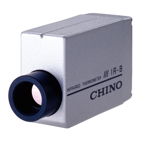
Chino IR-BZ Series User manual

INST.No.INE-559-P1
IR-BZ Series
COMPACT INFRARED
THERMOMETER
Model: IR-BZP
Always keep this instruction with the unit.
Please be sure to deliver these instructions
with the unit to the end user.


INST.No.INE-559-P1
-Contents-
Contents
PREFACE/ Request and notices
Important explanation
Warning and attention for the security
1. Introduction ................................................................. 1
1.1 Outline..................................................................... 1
2. Model .......................................................................... 1
2.1 Model...................................................................... 1
2.2 Configuration.......................................................... 1
3. Names and functions of component parts.................... 2
3.1 Main unit................................................................. 2
3.1.1 Overview.............................................................. 2
3.1.2 Function key and Digital display ......................... 3
3.1.3 Function keys....................................................... 3
3.1.4 Markers ................................................................ 3
4. Installation................................................................... 4
4.1 Installation of Main unit.......................................... 4
4.2 Installation of Detector............................................ 4
4.3 Measuring Diameter and Measuring Distance........ 5
5. Connections and Wirings............................................. 6
5.1 Connection to the Main unit.................................... 6
5.2 Connections to input and output terminals.............. 7
5.2.1 Terminal arrangement and terminal nameplate.... 7
5.2.2 Connection of power supply terminal.................. 7
5.2.3 Connection of grounding terminal....................... 7
5.2.4 Connection to receiving devices .......................... 7
6. Operating..................................................................... 8
6.1 Digital display......................................................... 8
7. Start option/Parameter diagram................................... 9
7.1 Start option.............................................................. 9
7.2 Display mode .......................................................... 9
7.3 Parameter diagram ................................................ 10
8. Operating mode ..........................................................11
◇Details of operating mode....................................... 12
8.1 Emissivity setting.................................................. 12
8.2 Transmittance setting ............................................ 12
8.3 Signal modulation mode selection........................ 13
8.4 Modulation degree setting..................................... 14
8.4.1 Setting of modulation time constant .................. 14
8.4.2 Selection of attenuation/Increase rate ................ 14
8.5 Alarm setting......................................................... 15
8.5.1 Alarm type selection........................................... 15
8.5.2 Temperature setting of alarm.............................. 15
9. Engineering mode...................................................... 16
◇Details of engineering mode................................... 17
9.1 Key lock set/release .............................................. 17
9.2 Selection of analog output..................................... 18
9.2.1 Setting of analog output minimum value........... 18
9.2.2 Setting of analog output maximum value .......... 19
9.3 Analog dummy output........................................... 19
9.3.1 Analog dummy output1...................................... 19
9.3.2 Analog dummy output2...................................... 20
9.4 Selection of hold function..................................... 21
9.4.1 Selection of hold reset type................................ 22
9.4.2 Setting of hold reset time ................................... 23
9.5 Measurement unit selection................................... 23
9.6 Setting of time constant digit after
decimal Point ................... 24
9.7 Selection of contact input...................................... 25
9.8 Selection of contact output.................................... 26
9.9 Selection of sub display ........................................ 26
9.10 Setting of device address..................................... 27
9.11 Selection of communication speed...................... 27
10. Self-diagnostic function and
Overflow/underflow indication.................. 28
10.1 Self-diagnostic function...................................... 28
10.2 Overflow/underflow indication........................... 28
11. Maintenance............................................................. 29
11.1 Regular inspection............................................... 29
11.2 Troubleshooting................................................... 29
11.2.1 Measuring value not displayed or
displayed lower ............. 29
11.2.2 Measuring value displayed higher.................... 29
11.2.3 Indication fluctuates......................................... 29
11.2.4 oFL or uFL is displayed.................................... 29
12. Specifications........................................................... 30
12.1 Specifications...................................................... 30
13. Parameter selection/ setting..................................... 31
13.1 List of parameter selection/ setting
(operating mode)........ 31
13.2 List of parameter selection/ setting
(engineering mode)...... 32
14. Initialization method................................................ 33
15.External dimensions.................................................. 34
15.1 IR-BZP Main unit................................................ 34
15.2 IR-BZP Detector ................................................. 35
15.3 Connecting cable IR-ZBP□□□............................ 35
15.4 Mounting bracket for Detector IR-ZBMP........... 36
15.5 DIN-rail mounting base for
Main unit IR-ZBDP............. 36

INST.No.INE-559-P1
-C1-
PREFACE/ Request and notices
Request to the operator of the thermometer
Follow this instruction manual and use the thermometer correctly.
This instruction manual describes the maintenance of the thermometer, too.
Keep this manual with due care until this thermometer is discarded.
If you have unclear points or need technical assistance, please contact your sales agent of CHINO
Corporation.
NOTE
1. The descriptions of this manual are subject to change without notice.
2. If a question has arisen or if an omission was found in this manual, please contact your nearest
CHINO’s sales agent or your dealer.
3. Copy right of this instruction manual belongs to CHINO Corporation. All or part of this instruction
manual shall not be released to the third party.
Thank you for purchasing IR-BZ Series Compact Infrared Thermometer.
Please read this instruction manual for using this thermometer correctly, safely and also
preventing troubles in advance.

INST.No.INE-559-P1
-C2-
Important explanation
To use this instrument correctly and safely, make sure to observe following safety precautions.
1. Working conditions and environment
●The working temperature range of this product is; -20 to 100°C for Detector and -10 to 65°C for Main
unit. (No dew condensation)
●Do not use in atmospheres such as a dust, garbage, the corrosive gas.
●This product is a precision instrument. Avoid using in the places where; temperature changes widely,
humidity is high, static electricity exist, heavy electric circuit exist or inductive interference is large and
mechanical vibration and impact exist.
●Tip of Detector is glass lens. Dropping or impact may cause damage to the unit. Take due care when
using.
2. Storage
●Do not store the thermometer in hot and humid places.
●For failures of the thermometer, don’t overhaul it by yourself, and contact your sales agent of CHINO
Corporation.
3. Disposal
●When you discard this product, please obey the regulation of each local government.
4. Symbols in this instruction manual
The symbols shown below are used depending on important degrees for using the thermometer safely and
avoiding unexpected situations.
Important
d
egree
Symbols Contents
1 This symbol is indicated with a title for an explanation with .
2Indicates important information that must be observed to avoid the risk
of fire or electric shock or other dangers that may result in serious
personal injury or death, or damage to this product.
3Indicates important information that must be observed to avoid the risk
of personal injury or malfunctions of this product.
4Indicates supplementary information that the operator is
recommended to
understand.
5 Indicates supplementary information or a reference to an operation.
!
Caution
Reference
Remarks
Warning
!
Warning

INST.No.INE-559-P1
-C3-
Warnings and Cautions
◆To use this product, make sure to observe following matters and use it correctly.
In addition, keep this instruction manual carefully in the place that you can reach at any time.
Shows an act of the prohibition.
Warning (May cause death or serious injury)
Don’t operate this thermometer in places where combustible or volatile gas is existed.
It is extremely dangerous to use the thermometer in such environment.
When connecting power to the power terminals, make sure to turn OFF power s
upply to
prevent an electric shock.
Don’t use the thermometer if it is broken, smoking or abnormal order is detected.
These may cause fire. For such abnormal conditions, turn off the power supply
immediately and contact your sales agent of CHINO Corporation.
Disassembling or modifying this thermometer may not only cause failure but also be
dangerous to you. Disassembling or modifying this thermometer is prohibited.
Caution (May cause injury or physical damage)
Avoid using in the places where; temperature changes widely, humidity is high, close to
heavy electric circuit exist, inductive interference is large, static electricity exists or
magnetic field, and mechanical vibration and impact exist. Also avoid using under the
atmosphere where dust and particles exist, corrosive gas exists and electric noise or static
electricity exists and easily to interrupt.
Do not wire the connection cable near a noise source; relay drive line and power line.
Do not bundle the connection cable with the line that noise is overwrapping, and do not
store it into the same duct.
To use the thermometer safely, strictly observe the contents described in this instruction
manual.
If the contents of this instruction manual are not complied, damage to the thermometer,
functional decline or damage to a system may occur.
!
!
!
!
!
!
!
!
!
!

INST.No.INE-559-P1
-1-
1. Introduction
1.1 Outline
IR-BZP "Compact Infrared Thermometer" is composed of a Main unit, which CPU is built-in and various
function settings are available from digital display and key operation, and Detector.
Heat resistance for a Detector is 100°C and it is also water-proof (IP65 equivalency) so it is excellent in
environmental resistance.
2. Model
2.1 Model
IR-BZ (1) (2) (3) E (4) (1) Type
P: Separate
(2) Element
H: Thermopile (high speed)
(3) Distance and diameter
G:φ8/200
(4) Cable length
1:1.5m
3:3m
8:8m *1)
F: 15m *1)
*1) CE marking non-approved
*2) Conformity requirements:Use of power supply for IR-BZ exclusive use and the connecting
cable up to 30m (indoor use)
2.2 Configuration
D
etector
Main
unit
EN61326-1 ClassA
- marking
Detector is connected to the
main unit prior to a shipment.
Detector can not be removed.
Caution

INST.No.INE-559-P1
-2-
3. Names and functions of component parts
3.1 Main unit
3.1.1 Overview
(1) Digital display
Main display: LCD 4-digits, Sub-display: LCD 4-digits,
Status marker: Alarm status
Sub-marker: Emissivity and Transmittance
Measurement unit: ºC or ºF
(2) Function key Three keys for displaying and setting parameters.
(3) Event lamp Lights when self-diagnostic alarm activates.
Also it will light when the contact output is set as ALM (high
or low alarm) and alarm activates.
(4) Cable gland (Detector side) Cable inlet for Detector (not removal).
(5) Cable gland
(Power supply and signal line side) Cable inlet for power supplyand signal line.
(6) Hole for installation φ4.5 two holes for fixing the unit.
(1) Digital display
(2) Function key
(4) Cable gland
Detector side
(5) Cable gland
Power supply and
signal line side
(6) Hole for installation
(3) Event lamp

INST.No.INE-559-P1
-3-
CONT PEAK
AL A H
º
C
ε
Tb MEM
º
F
3.1.2 Function key and Digital display
3.1.3 Function keys
Name Function Indication
(1) Select key Use for switching measurement mode, operating mode and
engineering mode, or for selecting parameters.
(2) Up key
(3) Down key Use for a setting item selection or for numeric value changing.
3.1.4 Markers
Main display:At measuring, measured value of the thermometer is displayed. At operating mode and
engineering mode, item selection or set value is displayed in 4-digit LCD.
Sub display:At measuring, error number, key lock status, detector temperature, main unit temperature is
displayed depending on the setting. At operating mode and engineering mode, parameter
name is displayed in 4-digit LCD. At emissivity setting, emissivity set value, and at
transmittance setting, transmittance set value is displayed.
Name Marker Function Indication
(4) Main marker
Tb
Not used.
"Tb"
CONT “CONT"
MEM "MEM"
PEAK "PEAK"
(5) Status marker AL It is lit at low alarm activation. "AL"
AH It is lit at high alarm activation. "AH"
(6) Measurement
unit ºCIt is lit when temperature is displayed in Celsius. "C"
ºFIt is lit when temperature is displayed in Fahrenheit. "F"
(7) Sub-marker εIt is lit at displaying emissivity. "ε"
rIt is lit at displaying transmittance. "r"
SEL
(4) Main
marker
(5) Status
marker
Main display
(7) Sub-marker
(6) Measurement
unit display Sub display
(1) Select key
(2) Up key
(3) Down key
SEL
Function key
(6) Measurement
unit display

INST.No.INE-559-P1
-4-
4. Installation
4.1 Installation of Main unit
Fix the Main unit by two installation holes.
4.2 Installation of Detector
Detector is fixed by screw. Make a hole on desired equipment and fix by attachment nut.
Fix a cable without looseness.
62
Do not use the thermometer at following places where;
●Dust, particles and corrosive gas are in the atmosphere
●Electric noise and static electricity are generated frequently
●Ambient temperature is 65°C or higher or -10°C or lower
●Ambient temperature changes widely or humid is high
●Close to high frequency line or power line
●Mechanical vibration and impact exist
●Flammable or explosive gases exist
Unit: mm
(12)
80
(17)
72
70
19.5
30
Cable gland
for power supply and
sign
al lines
Installation hole
2
-
φ
4.5
Cable gland
for Detector (not removal)
10
Compatible cable
diameter:φ6.5 to φ8
62
Unit: mm
28
10
M12 P1
φ14
Cable (1.5, 3, 8 or 15m)
Outer diameter:φ3.3
Caution
Cable vibration will be the cause of noise so please fix it to not to vibrate.
Cable allowable bending radius is 20mm.
When screwing the nut, do not co-around the detector. If co-around then it will
cause cable disconnection.
Caution

INST.No.INE-559-P1
-5-
4.3 Measuring Diameter and Measuring Distance
Unit: mm
φ
1
6
φ
8
400
200

INST.No.INE-559-P1
-6-
5. Connections and Wirings
5.1 Connection to the Main unit
Detector is connected prior to a shipment. Connect a cable at the power supply and signal line. Use
dedicated cable or commercial cable (twisted-pair cable with a shield, outer diameter φ6.5 to φ8.0,
wire size 0.2 to 0.5mm2.). Connect cable shield to FG. If using thermocouple output, use extension wire
according to the thermocouple type. Conditions for cable length are as follow.
Cable length Wire size Power supply voltage
5m or shorter 0.2mm
2
(AWG24) or more 8V or higher
50m or shorter 0.2mm
2
(AWG24) or more 9.5V or higher
100m or shorter 0.3mm
2
(AWG22) or more 9.5V or higher
200m or shorter 0.3mm
2
(AWG22) or more 11V or higher
(1) Loosen four of M3 screws of Main unit and remove a lid.
(2) Set a cable to the cable gland and connect to a terminal block. Press a button on the terminal block
while inserting the wire and release the button after the insertion.
To prevent an electric shock, turn OFF the power source for wiring.
M3 screw
Warning
!
Terminal blockTerminal block
Cable gland
Button
Wire
9
If taking out the lid, please conduct at clean
condition such as no dust.
If take out the lid, please do not touch the
electronical parts other than terminal block
by screw driver or remove the screw.
Warning
Warning
FG
8-36VDC
0VDC
SA
SB
DI
DO
COM
A GND
OUT-A mA
OUT-TC
OUT-HT

INST.No.INE-559-P1
-7-
5.2 Connections to input and output terminals
5.2.1 Terminal arrangement and terminal nameplate Connecting cable IR-ZBP
(Color) (Marker)
FG Grounding Gray FG
8-36VDC Power supply Red 8-36VDC
0VDC White/Red 0VDC
SA Communication Black SA
SB White/Black SB
DI Contact input Yellow DI
DO Contact output White/Yellow DO
COM Common White/Brown COM
A GND Analog ground White/Green A GND
OUT-A mA Analog output
Green OUT-A/TC
OUT-TC Thermocouple
output
OUT-HT Detector
temperature output Brown OUT-HT
※Analog output and TC output can not be used at the same time. Please connect either signal to
be used.
5.2.2 Connection of power supply terminal
5.2.3 Connection of grounding terminal
5.2.4 Connection to receiving devices
Analog output is non-isolated 0 or 4 to 20mA DC, thermocouple EMF equivalent
voltage.
Connect output terminal and receiving devices to each other.
Contact output is open collector output.
Use connecting external device rated (30V, 50mA) or lower.
Use 8 to 36VDC for power supply
Applicable power wire is 0.2 to 0.5mm2.
Provide a low impedance earth ground (grounding resistance 100Ω or lower)
connection.
Warning
Caution
Caution
Remarks
!
When closing the lid after connection, confirm the packing is not sticking out from
the groove.
Caution
※
Make sure to turn OFF the power supply for preventing an electric shock when
connecting power terminal.

INST.No.INE-559-P1
-8-
6. Operating
When installation and connections are completed, turn ON the power supply.
6.1 Digital display
Prepare a measurement by displaying “- - - -”
on main display and “lnit” on sub display. Measured
value is displayed on the main display when measurement
is started.
"AL" or "AH" on status marker is lit when low alarm
or high alarm is activated.
(Only if alarm setting is set to low or high.)
Displaying "Lock" on sub display if key lock set is
selected.
(1) Main display: 7-segment LCD 4-digit.
Measured value and set value/ setting
item, selection value/ selection item
are displayed.
(2) Sub display: 7-segment LCD 4-digit.
At measurement, selected item
by SEL key and at setting,
setting item is displayed.
(3) Sub marker: ε…emissivity
r…transmittance
(4) Status marker: AL…low alarm
AH…high alarm
(5) Measurement unit display:
°C…Celsius
ºF…Fahrenheit
[Measurement Mode]
Only "main display" is lit and
nothing is displayed on sub display
and sub marker.
(1)
(2)
(3)
(4)
CONT PEAK
AL A H
º
C
ε
Tb MEM
r
º
F
(5)

INST.No.INE-559-P1
-9-
7. Start option/Parameter diagram
7.1 Start option
By key operation at start-up, following operation is performed.
Key operation Display mode Remarks
Chapter of
this manual
Press SEL key at
measurement mode Operating mode Parameter setting at
operating mode 8
Long press SEL key at
measurement mode Engineering mode Parameter setting at
engineering mode 9
7.2 Display mode
Screens to be digital displayed are roughly classified into following 2 types.
Type
Outline
Measurement mode
・Turn ON the power supply and start measuring
・By pressing the SEL key, it shift to parameter setting screen at the
operating mode and emissivity, transmittance, signal modulation and
alarm etc. selection/ setting become enabled.
(→ Refer to ◇Details of operating mode on "8. Operating mode")
Engineering mode
・By long pressing (about 2 sec.) on the SEL key, it shift to setting screen
at the engineering mode and key lock, analog output scaling, analog
dummy output, hold function, contact output, sub display selection and
communication setting etc. selection/ setting become enabled.
(→ Refer to ◇Details of engineering mode on "9. Engineering mode")
・By completing the setting up to "9.10 Selection of communication
speed", it returns to the measurement mode.
*If there is no key operation on operating mode and engineering mode for 1 minute, it returns to the
measurement mode automatically. Also long pressing on the SEL key shifts to the measurement mode
immediately.

INST.No.INE-559-P1
-10-
7.3 Parameter diagram
(Operating mode・Engineering mode)
Initial screen
Operating
mode
Emissivity
setting
Transmittance
setting
Signal
modulation
Modulation time
constant Attenuation/
Increase rate
Alarm types
Alarm
temperature
Measurement
mode
SEL
SEL
SEL
SEL
SEL
SEL
SEL
SEL
Signal
modulation
dELy
SEL
PEAk, VALL
Alarm types
Lo, Hi
Engineering
mode
Key lock
Set/ Release
Analog
output
selection
Analog output
lower limit
Analog output
higher limit
Analog
dummy output1 Analog
dummy output2
SEL
SEL
SEL
SEL
SEL
Select
hold function
Hold
reset types
Hold
reset time
SEL
SEL
SEL
SEL
Time constant
digit after
decimal point
SEL
Contact input
selection
SEL
SEL
Sub display
selection
SEL
Device address
SEL
Communication
speed
SEL
Long press on
the SEL key
Contact output
selection
Analog
output
selection
tCJ, tCk,
tCr, tCS
0-20, 4-20
Select
hold function
PEAk, VALL
no, SAMP
Hold
reset types no, Et
In
no

INST.No.INE-559-P1
-11-
8. Operating mode
1) [Measurement mode screen] is displayed by turning ON
the power supply.
2) Press SEL key to display [Operating mode screen] on
the right.
For how to set/select parameters, refer to each chapter.
Transition at pressing SEL key is shown on the right.
*It returns to the measurement mode by long pressing
(about 2 sec.) on SEL key.
It also returns to the measurement mode if no key
operation is performed for 1 minute.
Operating mode diagram
Operating
mode
Emissivity
setting
Transmittance
setting
Signal
modulation
Modulation time
constant
Alarm types
Alarm temperature
Measurement
mode
SEL
SEL
SEL
SEL
SEL
SEL
SEL
SEL
Signal
modulation
dELy
SEL
PEAk, VALL
Alarm types
Lo, Hi
no
Attenuation/
Increase rate

INST.No.INE-559-P1
-12-
◇Details of operating mode
Press SEL key at measurement mode to operating mode.
8.1 Emissivity setting
1) Press the SEL key from measurement mode screen to display
"ε"shown on the right figure. Present temperature is displayed
on the main display.
2) Press ↑key or ↓key and change setting numeric value for
emissivity.
Setting is completed by changing the numeric value.
3)It shifts to the next screen by pressing the SEL key.
8.2 Transmittance setting
1) Press the SEL key couple of times to display "r" shown on the
right figure on sub marker. Present temperature is displayed on
the main display.
2) Press ↑key or ↓key and change setting numeric value for
transmittance.
Setting is completed by changing the numeric value.
3) It shifts to the next screen by pressing the SEL key.
・Setting range is 1.999 to 0.100
・Default setting is 1.000
・Setting range is 1.999 to 0.100
・Default setting is 1.000
It returns to the measurement mode if no key operation is performed for 1 minute.
Main display
CONT PEAK
AL AHC
ε
Tb MEM
Sub display
Sub marker
[Emissivity]
Main display
CONT PEAK
AL AH C
Tb MEM
r
Sub displaySub marker
[Transmittance]
It returns to the measurement mode by long pressing (about 2 sec.) on SEL key.
Remarks
Caution
Remarks
Remarks

INST.No.INE-559-P1
-13-
【dELy】
【PEAk】 【VALL】
8.3 Signal modulation mode selection
Select form to modulate measurement signal (original signal).
Select "dELy" to display REAL that is based on original signal
and set modulation degree to 0.0.
1) Press the SEL key couple of times from measurement mode
screen to display "Modu" shown on the right figure on sub
marker.
2) Press ↑key or ↓key and change signal modulation.
Selection is completed by changing the display.
3) It shifts to the next screen by pressing the SEL key.
[Modes of signal modulation]
dELy
It displays the value that is based on first order lag of
time constant set at 8.4.1 Setting of modulation time
constant. When signal value fluctuates, it displays in
smooth form
PEAK
If temperature is rising, it displays the value based on
original signal.
If temperature is dropping, the value is displayed based
on attenuation rate setting. (Refer to 8.4.2 Attenuation/
Incarease rate setting)
VALL
VALL is the opposite process of PEAK.
If temperature is dropping, the value is displayed based
on original signal.
If temperature is rising, it displays the value is displayed
based on increase rate setting. (Refer to 8.4.2
Attenuation/Increase rate setting)
・Default setting is "dELy"
CONT PEAK
AL AH
Tb MEM
[PEAK]
Main display
CONT PEAK
AL AH
Tb MEM
Sub display
[dELy]
CONT PEAK
AL AH
Tb MEM
[VALL]
Remarks
Display Original
Display
Original Display
ispl
Original

INST.No.INE-559-P1
-14-
・Default setting is 0 (°C/sec.)
Range of value available to be set changes depending on modulation time constant's
digit after the decimal point
(Refer to 9.5 Setting of time constant digit after decimal point)
8.4 Modulation degree setting
If "dELy" is selected in signal modulation mode selection, degree of first order lag (modulation time
constant) can be adjusted by setting modulation time constant.
If "PEAk" or "VALL" is selected in signal modulation mode selection, signal attenuation rate after the
peak is traced or signal increase rate after valley is traced can be set.
8.4.1 Setting of modulation time constant
(This is valid only if "dELy" is selected for signal modulation)
When original signal value fluctuates, it displays and output in smooth form.
The time constant stands for response of 63% level to the step change of the original signal.
1) Press the SEL key couple of times from measurement mode
screen to display "tAu" shown on the right figure on sub display.
2) Press ↑key or ↓key and change numeric value of modulation
time constant.
Setting is completed by changing the numeric value.
3) It shifts to the next screen by pressing the SEL key.
8.4.2 Selection of attenuation/Increase rate
(This is valid only if "PEAk" or "VALL" is selected for signal modulation)
PEAk or VALL can be traced. Signal attenuation rate after the peak or signal increase rate after valley is
selected.
1) Press the SEL key couple of times from measurement mode
screen to display "dEC" shown on the right figure on sub
display.
2) Press ↑key or ↓key and change numeric value of
attenuation/increase rate.
Selection is completed by changing the display.
(Change in order of 0→2→5→10 or 10→5→2→0(°C /sec.))
3) It shifts to the next screen by pressing the SEL key.
Reference
Modulation degree setting is used with "8.3 Signal modulation selection "
・Setting range: 1-digit after the decimal point,
0.0 to 99.9(sec.)
2-digit after the decimal point,
0.00 to 9.99(sec.)
・Default setting is 0.00 (sec.)
・If time constant is 0.0 (sec.) on "dELy" setting,
it become REAL.
[Modulation time constant]
CONT PEAK
AL AH
Tb MEM
Main display Sub display
[A
ttenuati
on/Increase rate
]
Main display Sub display
CONT PEAK
AL AH
Tb MEM
Remarks
Remarks
Remarks
Caution
This manual suits for next models
1
Table of contents
Other Chino Thermometer manuals

Chino
Chino IR-BAT Series User manual

Chino
Chino IR-FA Series User manual

Chino
Chino TP-S Easy Thermo User manual

Chino
Chino IR-AH Series User manual

Chino
Chino IR-E Series User manual

Chino
Chino IR-CAK User manual

Chino
Chino IR-CZ Series User manual

Chino
Chino IR-CA series User manual

Chino
Chino IR-H Series User manual

Chino
Chino IR-SA Series User manual